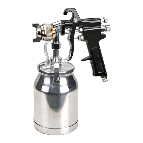
Grizzly T23092 User manual

MODEL T23092
HIGH-PRESSURE SPRAY GUN
OWNER'S MANUAL
(For models manufactured since 04/11)
COPYRIGHT © APRIL, 2011 BY GRIZZLY INDUSTRIAL, INC., REVISED FEBRUARY, 2022 (MN)
WARNING: NO PORTION OF THIS MANUAL MAY BE REPRODUCED IN ANY SHAPE
OR FORM WITHOUT THE WRITTEN APPROVAL OF GRIZZLY INDUSTRIAL, INC.
#TS14062 PRINTED IN CHINA V1.02.22
***Keep for Future Reference***

This manual provides critical safety instructions on the proper setup,
operation, maintenance, and service of this machine/tool. Save this
document, refer to it often, and use it to instruct other operators.
Failure to read, understand and follow the instructions in this manual
may result in fire or serious personal injury—including amputation,
electrocution, or death.
The owner of this machine/tool is solely responsible for its safe use.
This responsibility includes but is not limited to proper installation in
a safe environment, personnel training and usage authorization,
proper inspection and maintenance, manual availability and compre-
hension, application of safety devices, cutting/sanding/grinding tool
integrity, and the usage of personal protective equipment.
The manufacturer will not be held liable for injury or property damage
from negligence, improper training, machine modifications or misuse.
Some dust created by power sanding, sawing, grinding, drilling, and
other construction activities contains chemicals known to the State
of California to cause cancer, birth defects or other reproductive
harm. Some examples of these chemicals are:
• Lead from lead-based paints.
• Crystalline silica from bricks, cement and other masonry products.
• Arsenic and chromium from chemically-treated lumber.
Your risk from these exposures varies, depending on how often you
do this type of work. To reduce your exposure to these chemicals:
Work in a well ventilated area, and work with approved safety equip-
ment, such as those dust masks that are specially designed to filter
out microscopic particles.

Model T23092 (Mfd. Since 04/11) -1-
SECTION 1: SAFETY
For Your Own Safety Read Instruction Manual
Before Operating This Equipment
The purpose of safety symbols is to attract your attention to possible hazard-
ous conditions. This manual uses a series of symbols and signal words which
are intended to convey the level of importance of the safety messages. The
progression of symbols is described below. Remember that safety messages by
themselves do not eliminate danger and are not a substitute for proper accident
prevention measures.
Indicates an imminent hazardous situation which, if
not avoided, WILL result in death or serious injury.
Indicates a potentially hazardous situation which, if
not avoided, COULD result in death or serious injury.
Indicates a potentially hazardous situation which, if
not avoided, MAY result in minor or moderate injury.
It may also be used to alert against unsafe practices.
This symbol is used to alert the user to useful infor-
mation about proper operation of the equipment.
NOTICE
Safety Instructions for Spray Guns
OWNER’S MANUAL. This gun may cause
personal injury if used incorrectly. This
manual contains proper safety and operat-
ing instructions that must be followed to
reduce this risk.
EYE PROTECTION. Material sprayed into
eyes may cause serious injury or blind-
ness. Always wear safety goggles ANSI
approved for spraying (sealing type) to
reduce your risk from this hazard.
HAZARDOUS PARTICLES. Airborne
particles and fumes are toxic and can
cause brain damage or death. To reduce
your risk, only use the spray gun in a well
ventilated area with adequate supply of
fresh air.
WEARING A RESPIRATOR. Airborne
material from spraying can be very haz-
ardous to lungs. Always wear a NIOSH-
approved respirator for spraying and fumes
of your material type; or use a supplied air
respirator system that delivers fresh air
from an outside location via hoses.
HEARING PROTECTION. Pressurized
spray guns or hoses may burst unexpect-
edly if damaged or poorly maintained,
causing serious injury. Fix air leaks imme-
diately and follow all recommended main-
tenance. Never operate this spray gun with
loose or disassembled components. Never
modify the spray gun.

Model T23092 (Mfd. Since 04/11)-2-
USE CORRECT AIR PRESSURE.
Exceeding the maximum PSI rating of
this spray gun may cause unpredictable
operation or bursting.
DISCONNECT AIR PRESSURE. Before
servicing, changing accessories, or mov-
ing to another location. Never leave this
spray gun unattended when connected
to air.
AVOID IGNITION SOURCES. Spraying
around ignition sources may cause fire
or an explosion. Do not spray around
any ignition sources or potential ignition
sources. Be aware of appliances that
have pilot lights or machinery that creates
sparks during operation. Do not smoke in
the spraying area or when spraying.
BE AWARE OF HOSE LOCATION.
Hoses can easily become a tripping haz-
ard when laid across the floor in a disor-
ganized fashion.
AVOID UNINTENTIONAL OPERATION.
Always disconnect air when not in use,
and do not carry tool with hand on trigger.
KEEP CHILDREN AWAY. Prevent chil-
dren from injury by keeping them away
from this spray gun. Disconnect and lock
the spray gun away when not in use.
AVOID USE WHEN TIRED OR ON
DRUGS OR ALCOHOL. Avoid using this
spray gun if you are overly tired or intoxi-
cated. Using this spray gun during these
times may increase the risk of injury or fire.
UNTRAINED & UNSUPERVISED USE.
Untrained operators are not aware of the
safe use of this spray gun and may injure
themselves or cause fire. All untrained
operators must be directly supervised at
all times if using this spray gun.
READ MATERIAL LABELS and
MATERIAL SAFETY DATA SHEETS
(MSDS). Read and know all the instruc-
tions on the packaging label and the
MSDS before opening the package. This
information could save your life.
PROTECTIVE CLOTHING. Protect
exposed skin from overspray by wearing a
protective suit or other approved garment.
INAPPROPRIATE USE. DO NOT point
or shoot spray gun directly at yourself or
another person or animals. Do not attempt
to use the spray gun for any other use
than it was intended.
STORAGE. Thoroughly clean and dry
spray gun before storage. Store in an
approved cabinet.
FIRE EXTINGUISHERS. Always have a
fully charged multi-class or class B fire
extinguisher in the immediate area.
SOLVENTS. Always store solvents and
shop towels soaked in solvent in approved
containers.
LOCAL LAWS. Consult local authorities
regarding exhaust and waste disposal
requirements.
No list of safety guidelines can be complete. Every shop environment is different.
Always consider safety first, as it applies to your individual working conditions.
Use this and other machinery with caution and respect. Failure to do so could
result in serious personal injury, damage to equipment or poor work results.
Model T23092 (Mfd. Since 04/11) -3-
SECTION 2: INTRODUCTION
Type of Feed ............................................................................................................... Siphon
Viscosity Range .............................................................................................Medium to High
Waterborne Material Compatible ........................................................................................No
Nozzle Size .................................................................................................................... 2mm
Maximum Pattern Width .................................................................................................. 9 in.
Air Inlet Size .............................................................................................................1/4" NPT
Fluid Cup Capacity ....................................................................................................... 1 Liter
Average Air Consumption ................................................................................... 6 - 8.8 CFM
Operating Air Pressure ......................................................................................... 44 - 58 PSI
Cup Construction .................................................................................................... Aluminum
Gun Body Construction .................................................................................... Painted Metal
Specifications
We are proud to offer this manual with your
new spray gun! We've made every effort
to be exact with the instructions, specifica-
tions, drawings, and photographs we used
when writing this manual. However, some-
times we still make an occasional mistake.
Also, owing to our policy of continuous
improvement, your spray gun may not
exactly match the manual. If you find this
to be the case, and the difference between
the manual and spray gun leaves you in
doubt, check our website for the latest
manual update or call technical support
for help.
For your convenience, we post all avail-
able manuals and manual updates for free
on our website at www.grizzly.com. Any
updates to your model of machine will be
reflected in these documents as soon as
they are complete.
Foreword Contact Info
We stand behind our tools. If you have
any service questions, parts requests or
general questions about the tool, please
call or write us at the location listed below.
Grizzly Technical Support
1815 W. Battlefield
Springfield, MO 65807
Phone: (570) 546-9663
E-Mail: techsupport@grizzly.com
We want your feedback on this manual.
If you can take the time, please email or
write to us at the address below and tell
us how we did:
Grizzly Industrial, Inc.
C/O Technical Documentation Manager
P.O. Box 2069
Bellingham, WA 98227-2069
Email: manuals@grizzly.com

Model T23092 (Mfd. Since 04/11)-4-
Identification
Become familiar with the names and locations of the controls and features shown below to
better understand the instructions in this manual.
A. Fluid Control: Controls volume of
material that travels through fluid noz-
zle and past atomizer cap.
B. Pattern Control: Adjusts spray output
between round pattern and wide fan.
C. Storage Hook: Allows spray gun to be
temporarily stored in a vertical position
to avoid material spills.
D. Atomizing Cap: Atomizes material as
it is sprayed from nozzle. Adjusts for
horizontal or vertical spray patterns.
E. Fluid Nozzle: Sprays material past
atomizer cap.
F. Vacuum Relief Hose: Allows air to
flow into fluid cup as needed to prevent
vacuum buildup.
G. Fluid Cup Lock Lever: Releases/
engages pressure between cup hooks
and pins.
H. Cup Hook & Pin: Secures lid assem-
bly to cup when pressure is applied by
lock lever.
I. Fluid Cup: Holds material to be sprayed.
J. Two-Stage Trigger: Stage one releas-
es compressed air for blowing off
workpiece. Stage two sprays material.
Lightly squeeze trigger for stage one;
squeeze trigger all the way to spray
material.
K. Air Inlet: 1⁄4" NPT connection for com-
pressed air hose.
To reduce your risk of
serious injury, read this
entire manual BEFORE
using machine.
Figure 1. Model T23092 identification and controls.
B
A
J
F
K
C
D
E
G
I
H

Model T23092 (Mfd. Since 04/11) -5-
SECTION 3: SETUP
This tool presents serious injury
hazards to untrained users. Read
through this entire manual to
become familiar with the controls
and operations before starting the
tool!
Unpacking
This tool was carefully packaged for safe
transport. When unpacking, separate all
enclosed items from packaging materials
and inspect them for shipping damage.
If items are damaged, please call us
immediately at (570) 546-9663.
IMPORTANT: Save all packaging materi-
als until you are completely satisfied with
the tool and have resolved any issues
between Grizzly or the shipping agent. You
MUST have the original packaging to file a
freight claim. It is also extremely helpful if
you need to return the tool later.
Like all tools there is potential
danger when operating this tool.
Accidents are frequently caused by
lack of familiarity or failure to pay
attention. Use this tool with respect
and caution to decrease the risk of
operator injury. If normal safety pre-
cautions are overlooked or ignored,
serious personal injury may occur.

Model T23092 (Mfd. Since 04/11)-6-
The following is a list of items shipped
with your tool. Before beginning setup, lay
these items out and inventory them.
If any non-proprietary parts are missing
(e.g. a nut or a washer), we will gladly
replace them; or for the sake of expediency,
replacements can be obtained at your
local hardware store.
Box 1 (Figure 2) Qty
A. Fluid Cup ............................................1
B. Spray Gun Body ................................1
C. Multi-Wrench (not shown) ..................1
If you cannot find an item on this
list, carefully check around/inside
the tool and packaging materials.
Often, these items get lost in pack-
aging materials while unpacking or
they are pre-installed at the factory.
Figure 2. Inventory.
A
B
Assembly
Prior to assembly and use of the spray
gun, it is essential that all parts be thor-
oughly cleaned and dried. Please refer to
Cleaning on Page 12 for more detailed
instructions.
Make sure all connections are tight enough
to prevent air leaks but not so tight as to
damage the tool.
Attach the gun body to the fluid cup
assembly, as shown in Figure 3. Make
sure the connection is tight to prevent
leaks.
Figure 3. Example of attaching spray gun
body to fluid cup.
For the best results, use a hose that
will be dedicated for spray use only.
Do not use a hose that has been
used with an in-line oiler or other
possible contaminant. Always install
an air pressure regulator between
the air hose and the gun.
Inventory

Model T23092 (Mfd. Since 04/11) -7-
SECTION 4: OPERATIONS
To reduce your risk of
serious injury, read this
entire manual BEFORE
using machine.
If you are not experienced with this
type of tool, WE STRONGLY REC-
OMMEND that you seek additional
training outside of this manual.
Read books/magazines or get for-
mal training before beginning any
projects. Regardless of the content
in this section, Grizzly Industrial
will not be held liable for accidents
caused by lack of training.
To reduce risk of eye injury from
paint spray or lung damage from
breathing dust, always wear safety
goggles and a NIOSH-approved res-
pirator when operating this tool.
Spraying
The Model T23092 high-pressure spray
gun is designed to spray a wide variety
of materials, such as lacquers, stains,
primers, multi-component paints, clear
coats, acrylics, epoxies, etc. It is ideal for
auto body and woodworking projects. This
spray gun is not designed to be used with
waterborne materials.
To operate spray gun:
1. DISCONNECT SPRAY GUN FROM
AIR!
2. Read and follow material manufac-
turer's instructions for spraying, mixing,
safety, disposal, and any other instruc-
tion on the label or Material Safety Data
Sheet (MSDS).
3. Move cup lock lever against vacuum
hose connection to release pressure
between cup hooks and pin—this will
disengage cup lid from cup.
TOXIC FUME
HAZARD!
Always use an approved
spray booth or well-
ventilated area when
spraying to avoid breath-
ing toxic vapors.
INJURY HAZARD!
Disconnect tool from
air to prevent unex-
pected operation dur-
ing service.
INJURY HAZARD!
Never exceed max PSI
rating for tool.
EXPLOSION
HAZARD!
Do not spray flammable
fluids near open flame
or ignition source.

Model T23092 (Mfd. Since 04/11)-8-
6"
12"
Correct Incorrect
Figure 5. Spraying technique.
Tipping the spray gun may cause
material to spill out of the cup.
Always hold the spray gun parallel to
the ground to avoid potential spills
and feed problems.
4. Fill fluid cup with desired material, then
place it on a flat, stable surface.
5. Move lock lever against vacuum relief
hose connection, then place cup lid and
gun body assembly on cup
6. Engage cup pins with hooks, then
rotate lock lever clockwise until lid is
firmly secured.
To ensure the fluid cup does not leak
or spill material during the spraying
operation, always make sure the cup
is securely sealed to the lid with
both pins fully engaged with the
hooks.
Note: Trial and error are necessary to
achieve the results you want, as well a
fair amount of practice. Test your mate-
rial flow and spray pattern on a piece
of cardboard or some scrap of material
similar to your project.
10. Adjust fluid control knob to start with
a low volume of material, and keep
atomization as low as possible. Use
a combination of fluid control, inlet air
pressure, air flow control, and stroke
speed to achieve desired results. Spray
so material wets out nicely without run-
ning or sagging.
11. Use pattern control knob to adjust
spray fan to desired pattern.
12. Keep gun tip perpendicular, parallel
and 6"–12" from workpiece at all times
when spraying (see Figure 5.) Do not
allow your wrist to bend. This will cause
gun to arc across surface and distribute
material unevenly, possibly creating
sags and dry spots.
7. Set inlet air pressure (air coming into
spray gun) to lowest operating air pres-
sure recommended in Specifications
on Page 3 or to material manufac-
turer's recommendations.
8. Connect spray gun to compressed
air source. To improve tool lifespan
and avoid contaminating material with
water from air supply lines, use a filter/
lubricator/regulator setup, as shown in
Figure 4.
Quick
Connector
Quick
Coupler
Air Hose
Quick
Coupler
Quick
Connector
Lubricator
Filter
Regulator
Your
Tool
Air
Compressor
Figure 4. Installed filter/lubricator/
regulator.
9. Adjust atomizing cap to vertical or
horizontal (see Atomizing Cap
Adjustment on Page 9).

Model T23092 (Mfd. Since 04/11) -9-
13. Begin spraying 2"–3" in front of
workpiece and continue motion for a
few inches past workpiece until ready
for return stroke.
14. Maintain an even speed when spray-
ing, and overlap each stroke by 50%.
This will ensure even coverage, as
shown on left in Figure 6. Overlapping
less than 50%, as shown on right in
Figure 6, may lead to missed spots or
streaky results.
6"
12"
Correct Incorrect
Figure 6. Overlapping technique.
15. Spray stroke should have even consis-
tency and parallel edges. If it does not,
refer to Troubleshooting on Page 14.
Atomizing Cap
Adjustment
To ensure good spraying results, the atom-
izing cap must be correctly oriented for
the direction of the stroke pattern—either
horizontal or vertical.
Spraying in the wrong direction may lead
to material buildup on the atomizing cap
horn. Many performance problems are
caused by clogged atomizing holes. In this
case, clean the spray gun (see Cleaning
on Page 12).
If the stroke pattern is side to side, the horns
of the atomizing cap must be arranged
horizontally, as shown in Figure 8.
Conversely, if the stroke pattern is up and
down, the atomizing cap horns should be
vertical, as shown in Figure 9.
Pattern Control
The pattern control knob on the rear of the
gun body controls the spray output, from a
round pattern to a wide fan, as illustrated
in Figure 7.
Figure 7. Range of spray patterns. Figure 9. Atomizing cap set up for up-and-
down stroke pattern (front view).
Figure 8. Atomizing cap set up for side-to-
side stroke pattern (front view).

Model T23092 (Mfd. Since 04/11)-10-
SECTION 5: ACCESSORIES
Refer to our website or latest cat-
alog for additional recommended
accessories.
Installing unapproved accessories
may cause tool to malfunction,
resulting in serious personal inju-
ry or tool damage. To reduce this
risk, only install accessories recom-
mended for this tool by Grizzly.
order online at www.grizzly.com or call 1-800-523-4777
Figure 11. H7274 Campbell Hausfeld™
Pressure Regulator.
H7274—Campbell Hausfeld™ Compact
Pressure Regulator
Mini Series. Provides regulated output
pressure of 0–125 PSI for proper tool
operation. Locking pressure knob pre-
vents accidental adjustments. Includes
0–60 PSI pressure gauge. 15 SCFM flow
capacity @ 90 PSI. 1⁄4" NPT.
Figure 10. G6261 Campbell Hausfeld™
Water Filter.
G6261—Campbell Hausfeld™ Water
Filter
Remove damaging water vapor before it
reaches your spray gun. This highly effec-
tive, 5-micron filter features a see-through
bowl and easy in-line connections. 21
SCFM flow capacity @ 90 PSI. 1⁄4" NPT. H2499—Small Half-Mask Respirator
H3631—Medium Half-Mask Respirator
H3632—Large Half-Mask Respirator
H3635—Cartridge Filter Pair P100
If you work around dust everyday, a half-
mask respirator can be a lifesaver. Also
compatible with safety glasses!
Figure 12. Half-mask respirator with
disposable cartridge filters.

Model T23092 (Mfd. Since 04/11) -11-
G8110 —1⁄4" NPT x 50' PVC Air Hose
This PVC air hose is designed to be oil,
kink, abrasion, ozone, and weather resis-
tant. Rated for 200 PSI. 1⁄4" NPT. Made in
the USA.
Figure 14. G8110 PVC Air Hose.
T32339—GrizzlyPRO 20-Gallon, 2HP,
Portable Air Compressor
The T32339 features a tank pressure
gauge, output pressure gauge, a quick
connect, and overload protection. It comes
with oversized no-flat wheels for increased
mobility. The 2 HP motor operates with a
maximum pressure of 135 PSI. The com-
pressor delivers 6.0 CFM at 90 PSI and
7.2 CFM at 40 PSI. The motor is prewired
for 110V, but it can be converted to 220V.
Figure 13. T32339 GrizzlyPRO Air
Compressor.
T20887—Campbell Hausfeld™ Air
Accessory Kit, 25-Pc.
Includes blowgun, safety nozzle, (2)
tapered inflation nozzles, (2) inflation nee-
dles, PTFE thread sealant tape, rubber
blowgun tip, female tire chuck, dual foot air
chuck, pencil tire gauge, coupler, (6) plugs
1⁄4" NPT (M), (2) male couplings, (2) female
couplings, and (2) plugs 1⁄4" NPT (F).
Figure 15. T20887 Campbell Hausfeld™
Air Accessory Kit.
order online at www.grizzly.com or call 1-800-523-4777

Model T23092 (Mfd. Since 04/11)-12-
SECTION 6: MAINTENANCE
To reduce the risk of injuries from
compressed air explosion, always
disconnect the air line before per-
forming maintenance or service.
Cleaning
Properly cleaning the spray gun helps to
ensure good spraying results and long gun
life. Always thoroughly clean the spray gun
after each use.
To clean spray gun:
1. Spray a small amount of cleaning sol-
vent through gun.
Note: Check with local laws regarding
this practice. If you are spraying on a
regular basis, spraying solvents into
the air may be illegal. A cabinet-style
spray gun cleaner may be required.
2. DISCONNECT SPRAY GUN FROM
AIR!
3. Remove cup and cup lid, then disas-
semble spray gun by unscrewing fluid
control knob and removing spring and
needle (see Figure 16).
4. Unscrew atomizing cap with your fin-
gers, then remove fluid nozzle with a
wrench. The fully disassembled gun
should look like Figure 16.
EXPLOSION HAZARD! Chlorinated
Solvents like 1,1,1-Tricloroethane
and Methylene Chloride (methyl
chloride) can chemically react with
aluminum and may explode. Many
parts in spray guns are made of alu-
minum. Read solvent label carefully
before using solvent.
Figure 16. Spray gun disassembled for
cleaning.
Atomizing Cap
Needle
Fluid Control
Knob
Washer
Fluid Nozzle
Cup Lid
Assembly
CupSpray
Gun

Model T23092 (Mfd. Since 04/11) -13-
5. Rinse these parts thoroughly in solvent,
then dry with compressed air or let air
dry.
Note: If small holes in atomizing cap
become blocked, soak cap in clean
solvent. If blockage still exists, clear
blockage with a small needle, taking
great care to not enlarge or damage
the hole. Damage to hole will create a
disrupted spray pattern.
6. Use an old tooth brush and solvent to
clean inner orifice and other hard-to-
reach areas on outside of gun body.
7. Wipe gun body dry with a lint-free shop
towel.
DO NOT soak spray gun body in sol-
vent. Prolonged exposure to solvent
will rapidly deteriorate spray gun
washers and seals.
Lubrication
Lubricate the following areas shown in
Figure 17 with a non-silicone spray gun
lubricant after each cleaning.
A. Fluid Control Knob
B. Pattern Control
C. Air Valve Packing
D. Atomizing Cap Threads
E. Trigger Pin
Allow the lubricant to coat the threads and
run into the gun body to lubricate all the
moving parts and seals.
Figure 17. Lubrication locations.
DC
A
B
E

Model T23092 (Mfd. Since 04/11)-14-
Troubleshooting
SECTION 7: SERVICE
Symptom Possible Cause Solution
Fluttering or spit-
ting spray.
1. Dry or worn fluid nozzle seat
permits air to seep into fluid
passage.
2. Material level too low.
3. Fluid nozzle obstructed.
4. Dry needle packing.
1. Tighten fluid tip or replace
seat with new one.
2. Add material.
3. Clean.
4. Lubricate needle.
Uneven top or bot-
tom pattern.
1. Atomizing cap holes are
obstructed.
2. Buildup on top or bottom of
fluid nozzle.
3. Buildup on atomizing cap or on
needle seat.
1. Clear holes.
2. Clean.
3. Clean.
Right or left arc
pattern.
1. Left or right side horn holes are
plugged.
2. Build-up on left or right side of
fluid tip.
3. Build-up of material inside
atomizing cap.
1. Clear holes.
2. Clean.
3. Clean.
Heavy deposit of
material in center.
1. The material flow exceeds the
atomizing cap capacity.
2. Inlet air pressure is too low.
3. Material is too thick.
1. Lower fluid flow.
2. Increase inlet air pressure.
3. Thin material.
Narrow center pat-
tern.
1. Fluid control turned in too far.
2. Inlet air pressure too high.
3. Fluid pressure is too low.
4. Material is too thin.
1. Lower fluid flow.
2. Reduce inlet air pressure.
3. Increase fluid pressure.
4. Adjust material.
Gun leaks from
fluid nozzle.
1. Debris will not let needle seat
with fluid nozzle.
1. Clean or replace both.
Troubleshooting

Model T23092 (Mfd. Since 04/11) -15-
Symptom Possible Cause Solution
No spray output. 1. No pressure at gun.
2. Fluid passages dirty.
3. Fluid control closed.
4. Out of paint.
5. Material too thick.
1. Check air supply.
2. Clean gun, remove any
obstructions.
3. Open.
4. Refill.
5. Thin to manufacturer's
recommendations.
Excessive over-
spray.
1. Fluid pressure too high.
2. Gun is too far from surface.
3. Spraying too fast.
1. Reduce fluid pressure.
2. Keep gun at recommended
distance.
3. Slow down and maintain
consistent, even, parallel
stroke.
Unable to control
spray fan.
1. Pattern adjustment screw is not
seating properly.
2. Atomizing cap is loose.
1. Clean or replace.
2. Tighten atomizing cap.
Runs and sags. 1. Damaged seal.
2. Too much fluid output.
3. Keeping gun in one place too
long.
1. Replace damaged seal(s).
2. Use fluid control to reduce
flow.
3. Keep gun moving at a
steady pace.
Material leaks from
cup.
1. Cap not secure.
2. Cup not tight on gun body.
3. Leaking from cap vent hole.
1. Tighten.
2. Tighten.
3. Hold gun upright; do not tilt.
Material leaks from
gun.
1. Fluid tip loose.
2. Dry or damaged seals.
3. Excessive pressure.
1. Tighten.
2. Replace seals.
3. Reduce pressure.
Thick, dimpled fin-
ish: orange peel
appearance.
1. Holding gun too close to
surface.
2. Inlet air pressure too low.
3. Material not properly mixed.
4. Surface is dirty or oily.
1. Spray at recommended
distance.
2. Check inlet air pressure.
3. Follow manufacturer's
instructions.
4. More surface prep is
required.
Dry spray. 1. Inlet air pressure too high.
2. Gun too far from surface.
3. Gun stroke too fast.
1. Lower inlet air pressure.
2. Keep gun at recommended
distance.
3. Slow down and maintain
even, parallel stroke.
Contaminated
paint: fish eye
appearance.
1. Water or oil in the air line. 1. Install an in-line air filter;
replace air line.
Review the troubleshooting and procedures in this section if a problem develops with your tool.
If you need replacement parts or additional help with a procedure, call our Technical Support.

Model T23092 (Mfd. Since 04/11)-16-
SECTION 8: PARTS
Main
Parts breakdown provided for reference only. Not all parts shown are available for purchase.
BUY PARTS ONLINE AT GRIZZLY.COM !
Scan QR code to visit our Parts Store.
1
2
489 10 11
12
13
14
18
15
19
20
21
22232425
34 27
28
29
303132
33
35
36
37
38
39
40
41
42
42
43
44
45
46 47 48
567
3
26
16
17
34
49
REF PART # DESCRIPTION REF PART # DESCRIPTION
1 PT23092001 AI R I NL ET CO NNECTO R 1 / 4" NPT 26 PT23092026 O-RING 8.5 X 1.2
2 PT23092002 I NLE T S CREW 27 PT23092027 DI RECTI ON SCREW
3 PT23092003 GUN BODY 28 PT23092028 COMPRESSION SPRING 0.8 X 7.3 X 30.2
4 PT23092004 NEEDLE HOUSING 29 PT23092029 TRIGGER STEM
5 PT23092005 FLUI D ADJ USTMENT NEEDLE 30 PT23092030 STEM WASHER
6 PT23092006 NEEDLE SLEEVE 31 PT23092031 O-RING 9 X 1.8
7 PT23092007 SP RI NG CO RE 32 PT23092032 STEM SEAT
8 PT23092008 FLAT WASHER 12.5 X 15.7 X 1 PL 33 PT23092033 FLAT WASHER 2. 8 X 8 X 1 FIBER
9 PT23092009 SP RI NG HO USI NG 34 PT23092034 O-RING 2 X 1.5
10 PT23092010 NEEDLE COMPRESSION SPRING 35 PT23092035 STEM SEAT NUT
11 PT23092011 FLUI D CONTROL KNO B 36 PT23092036 FLUI D I NLET NO ZZLE
12 PT23092012 PATTERN CO NTROL KNOB 37 PT23092037 I NLET HEX NUT
13 PT23092013 PATTERN NEEDLE SEAT 38 PT23092038 I NLET THI N NUT
14 PT23092014 O-RING 2.5 X 2.1 39 PT23092039 LOCK ARM
15 PT23092015 PATTERN SP RI NG 40 PT23092040 LOCK LEVER
16 PT23092016 FLAT WASHER 3. 2 X 6 X 0.5 41 PT23092041 FL UI D HO SE
17 PT23092017 PATTERN NE EDLE 42 PT23092042 HOSE CONNECTOR
18 PT23092018 EXT RETAI NI NG RI NG 4 MM 43 PT23092043 CUP LI D
19 PT23092019 TRIGGER 44 PT23092044 LID GASKET
20 PT23092020 TRIGGER PIN 45 PT23092045 SYPHON TUBE
21 PT23092021 CONNECTOR S CREW 46 PT23092046 FLUI D CUP
22 PT23092022 HEAD 47 PT23092047 CUP SCREW
23 PT23092023 NOZZLE 48 PT23092048 CUP PI N
24 PT23092024 FLAT WASHER 29 X 36. 8 X 5.5 PL 49 PT23092049 MULTI - WRENCH
25 PT23092025 ATOMI ZI NG CAP

WARRANTY & RETURNS
Grizzly Industrial, Inc. warrants every product it sells for a period of 1 year to the original purchaser from
the date of purchase. This warranty does not apply to defects due directly or indirectly to misuse, abuse,
negligence, accidents, repairs or alterations or lack of maintenance. This is Grizzly’s sole written warranty
and any and all warranties that may be implied by law, including any merchantability or fitness, for any par-
ticular purpose, are hereby limited to the duration of this written warranty. We do not warrant or represent
that the merchandise complies with the provisions of any law or acts unless the manufacturer so warrants.
In no event shall Grizzly’s liability under this warranty exceed the purchase price paid for the product and
any legal actions brought against Grizzly shall be tried in the State of Washington, County of Whatcom.
We shall in no event be liable for death, injuries to persons or property or for incidental, contingent, special,
or consequential damages arising from the use of our products.
The manufacturers reserve the right to change specifications at any time because they constantly strive to
achieve better quality equipment. We make every effort to ensure that our products meet high quality and
durability standards and we hope you never need to use this warranty.
In the event you need to use this warranty, contact us by mail or phone and give us all the details. We will
then issue you a “Return Number,’’ which must be clearly posted on the outside as well as the inside of
the carton. We will not accept any item back without this number. Proof of purchase must accompany the
merchandise.
Please feel free to write or call us if you have any questions about the machine or the manual.
Thank you again for your business and continued support. We hope to serve you again soon.
To
take advantage of this warranty, you must register it at https://www.grizzly.com/forms/warranty, or
you can
scan the QR code below to be automatically directed to our warranty registration page. Enter all
applicable information for
the product.
WARRANTY

Other manuals for T23092
1
Table of contents
Other Grizzly Paint Sprayer manuals

Grizzly
Grizzly H7668 User manual

Grizzly
Grizzly G0533 User manual

Grizzly
Grizzly H7671 User manual

Grizzly
Grizzly H8117 User manual

Grizzly
Grizzly H3253 User manual

Grizzly
Grizzly H8226 User manual

Grizzly
Grizzly H7666/H7667 User manual

Grizzly
Grizzly G5353 User manual

Grizzly
Grizzly H8115 User manual

Grizzly
Grizzly Model H8222 User manual

Grizzly
Grizzly H8225 User manual

Grizzly
Grizzly 385 000 Assembly instructions

Grizzly
Grizzly H8225 User manual

Grizzly
Grizzly H3266 User manual

Grizzly
Grizzly G5357 User manual

Grizzly
Grizzly G0533 Quick start guide

Grizzly
Grizzly H8226 User manual

Grizzly
Grizzly G5352 User manual

Grizzly
Grizzly H7673 User manual

Grizzly
Grizzly T23092 User manual