Grizzly G0948 User manual

MODEL G0948
10" 1/2 HP BANDSAW
OWNER'S MANUAL
(For models manufactured since 08/21)
COPYRIGHT © SEPTEMBER, 2021 BY GRIZZLY INDUSTRIAL, INC.
WARNING: NO PORTION OF THIS MANUAL MAY BE REPRODUCED IN ANY SHAPE
OR FORM WITHOUT THE WRITTEN APPROVAL OF GRIZZLY INDUSTRIAL, INC.
#MN22059 PRINTED IN CHINA V1.09.21

This manual provides critical safety instructions on the proper setup,
operation, maintenance, and service of this machine/tool. Save this
document, refer to it often, and use it to instruct other operators.
Failure to read, understand and follow the instructions in this manual
may result in fire or serious personal injury—including amputation,
electrocution, or death.
The owner of this machine/tool is solely responsible for its safe use.
This responsibility includes but is not limited to proper installation in
a safe environment, personnel training and usage authorization,
proper inspection and maintenance, manual availability and compre-
hension, application of safety devices, cutting/sanding/grinding tool
integrity, and the usage of personal protective equipment.
The manufacturer will not be held liable for injury or property damage
from negligence, improper training, machine modifications or misuse.
Some dust created by power sanding, sawing, grinding, drilling, and
other construction activities contains chemicals known to the State
of California to cause cancer, birth defects or other reproductive
harm. Some examples of these chemicals are:
• Lead from lead-based paints.
• Crystalline silica from bricks, cement and other masonry products.
• Arsenic and chromium from chemically-treated lumber.
Your risk from these exposures varies, depending on how often you
do this type of work. To reduce your exposure to these chemicals:
Work in a well ventilated area, and work with approved safety equip-
ment, such as those dust masks that are specially designed to filter
out microscopic particles.

Table of Contents
INTRODUCTION............................................... 2
Contact Info.................................................... 2
Manual Accuracy ........................................... 2
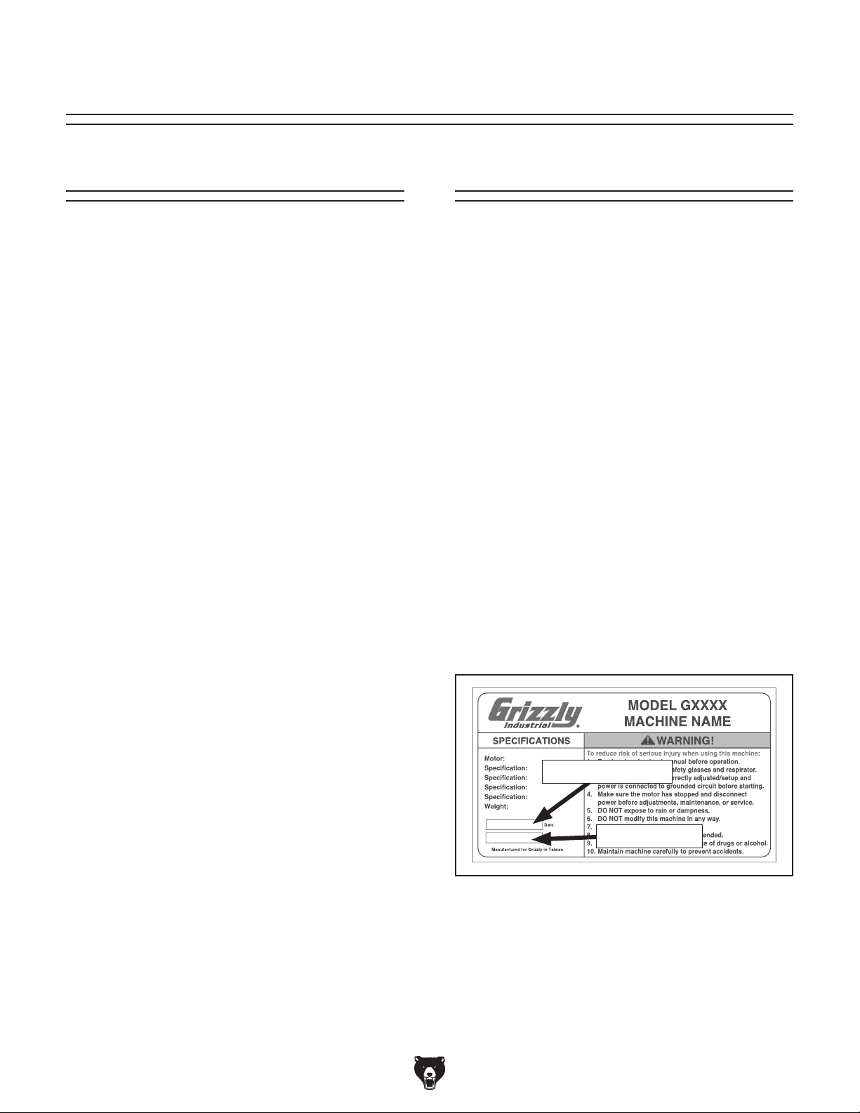
Identification ................................................... 3
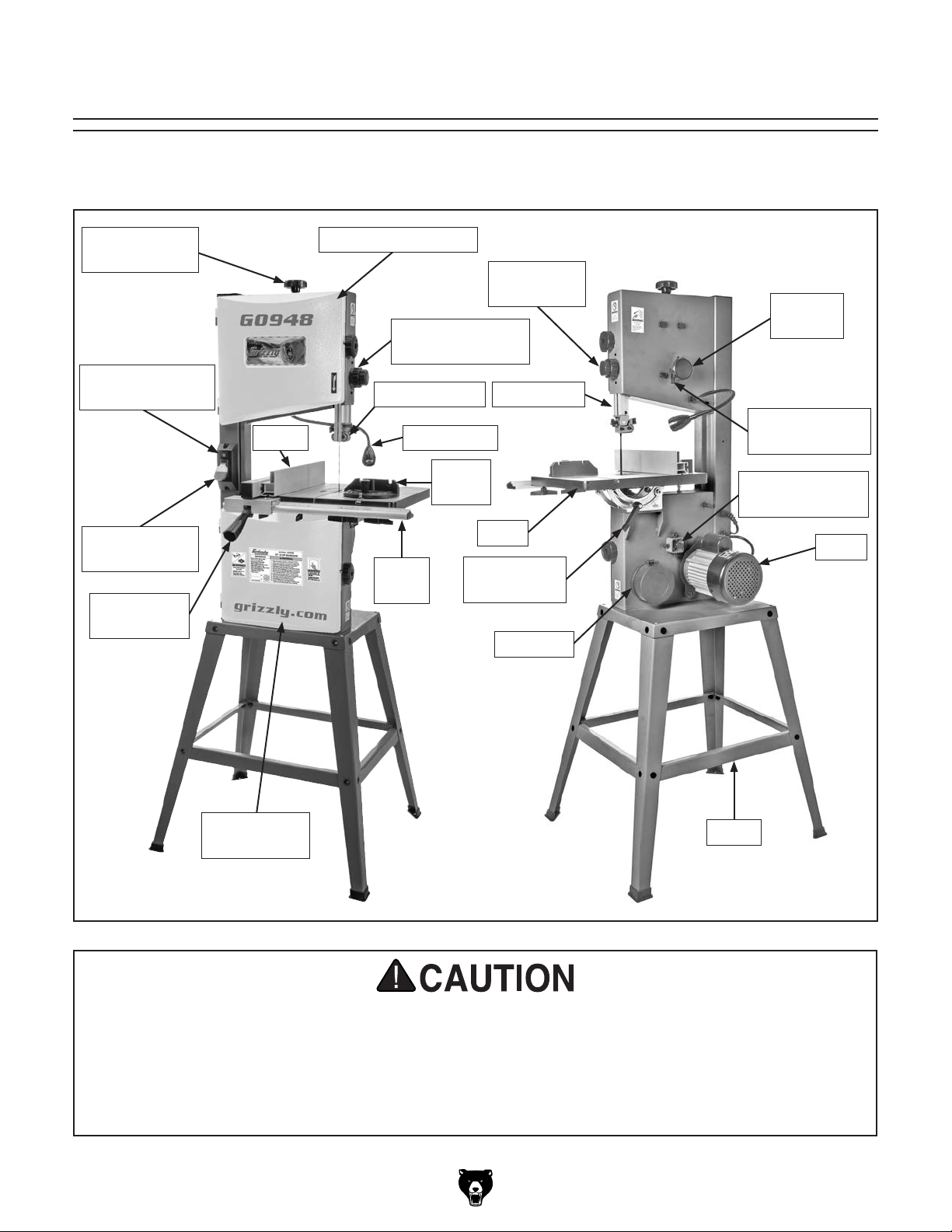
Controls & Components ................................. 4
Machine Data Sheet ...................................... 6
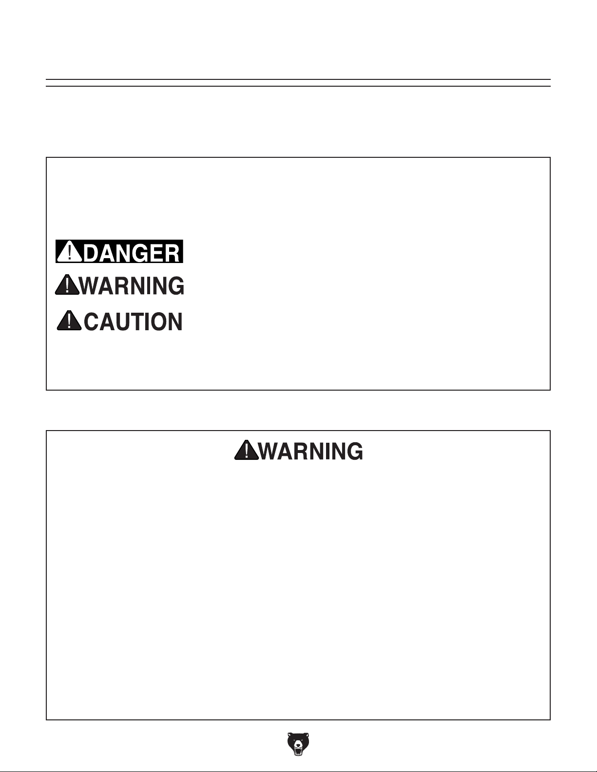
SECTION 1: SAFETY....................................... 8
Safety Instructions for Machinery .................. 8
Additional Safety for Bandsaws ................... 10
SECTION 2: POWER SUPPLY ...................... 11
SECTION 3: SETUP ....................................... 13
Unpacking .................................................... 13
Needed for Setup ......................................... 13
Inventory ...................................................... 14
Hardware Recognition Chart ....................... 15
Site Considerations ...................................... 16
Assembly ..................................................... 16
Dust Collection ............................................. 19
Adjustment Overview ................................... 19
Initial Blade Tracking ................................... 20
Test Run ...................................................... 21
Tensioning Blade ......................................... 22
Adjusting Blade Support Bearings ............... 24
Adjusting Blade Guide Bearings .................. 25
Aligning Table .............................................. 27
Aligning Fence ............................................. 28
Calibrating Miter Gauge ............................... 29
SECTION 4: OPERATIONS ........................... 30
Operation Overview ..................................... 30
Basic Functions of a Bandsaw .................... 31
Workpiece Inspection................................... 31
Setting Upper Blade Guide Height .............. 32
Tilting Table ................................................. 32
Choosing Blades .......................................... 34
Blade Selection Chart .................................. 37
Blade Care & Break-In ................................. 38
Blade Breakage ........................................... 38
Removing/Installing Blade ........................... 39
Changing Blade Speed ................................ 40
Ripping ......................................................... 41
Crosscutting ................................................. 41
Resawing ..................................................... 42
Cutting Curves ............................................. 42
Stacked Cuts................................................ 43
SECTION 5: ACCESSORIES......................... 44
SECTION 6: MAINTENANCE......................... 47
Schedule ...................................................... 47
Cleaning & Lubricating ................................. 47
SECTION 7: SERVICE ................................... 48
Troubleshooting ........................................... 48
Checking/Adjusting Belt Tension ................. 51
Replacing Belt .............................................. 52
Aligning Wheels ........................................... 53
Blade Lead ................................................... 56
Adjusting Wheel Brush ................................ 57
SECTION 8: WIRING...................................... 58
Wiring Safety Instructions ............................ 58
Wiring Diagram ............................................ 59
Electrical Components ................................. 60
SECTION 9: PARTS....................................... 61
Main ............................................................. 61
Labels & Cosmetics ..................................... 64
WARRANTY & RETURNS ............................. 65

-2- Model G0948 (Mfd. Since 08/21)
We stand behind our machines! If you have ques-
tions or need help, contact us with the information
below. Before contacting, make sure you get the
serial number
and manufacture date
from the
machine ID label. This will help us help you faster.
Grizzly Technical Support
1815 W. Battlefield
Springfield, MO 65807
Phone: (570) 546-9663
Email: [email protected]
We want your feedback on this manual. What did
you like about it? Where could it be improved?
Please take a few minutes to give us feedback.
Grizzly Documentation Manager
P.O. Box 2069
Bellingham, WA 98227-2069
Email: [email protected]
Contact Info
We are proud to provide a high-quality owner’s
manual with your new machine!
We
made every effort to be exact with the
instruc-
tions, specifications, drawings, and photographs
in this manual. Sometimes we make mistakes, but
our policy of continuous improvement also means
that
sometimes the machine
you receive is
slightly different than shown in the manual
.
If you find this to be the case, and the difference
between the manual and machine leaves you
confused or unsure about something
,
check our
website for an updated version. W
e post
current
manuals and
manual updates for free
on our web-
site at
www.grizzly.com.
Alternatively, you can call our Technical Support
for help. Before calling, make sure you write
down the
manufacture date and
serial number
from the machine ID label (see below). This
information is required for us to provide proper
tech support, and it helps us determine if updated
documentation is available for your machine.
Manufacture Date
Serial Number
Manual Accuracy
INTRODUCTION

Model G0948 (Mfd. Since 08/21)-3-
Identification
Become familiar with the names and locations of the controls and features shown below to better understand
the instructions in this manual.
For Your Own Safety,Read Instruction Manual Before Operating Saw.
a) Wear eye protection.
b) Do not remove jammed cutoff pieces until blade has stopped.
c) Maintain proper adjustment of blade tension, blade guides, and thrust bearings.
d) Adjust upper blade guide to just clear workpiece.
e) Hold workpiece firmly against table.
Upper Wheel CoverBlade Tension
Knob
Table Tilt
Lock Handle
Guide Post
Adjustment Knob
Guide Post
Lock Knob
Miter
Gauge
Lower Wheel
Cover
LED Work Light
ON/OFF Switch
ON/OFF
Paddle Switch
Fence Lock
Handle
Lower Wheel
Adjustment Hub
Tracking Knob
Lock Lever
Tracking
Knob
Dust Port
Stand
Fence
Guide Post
Fence
Rail
Table
Blade Guides
Work Light
Motor

-4- Model G0948 (Mfd. Since 08/21)
Controls &
Components
Refer to Figures 1–6 and the following descrip-
tions to become familiar with the basic controls
and components of this machine. Understanding
these items and how they work will help you
understand the rest of the manual and stay safe
when operating this machine.
To reduce your risk of
serious injury, read this
entire manual BEFORE
using machine.
Fence & Miter Gauge
Power Controls
A. ON/OFF Paddle Switch w/Removable Key:
Turns machine ON and OFF. Remove key to
disable machine.
B. LED Work Light ON/OFF Switch: Turns
light ON and OFF.Illuminates cutting area for
better visibility.
Figure 3. Fence mounted in horizontal position.
Horizontal Position
Allows Upper
Blade Guide to Be
Adjusted Closer to
Thin Workpieces
C. Fence: Used for ripping or resawing. Distance
from blade determines width of cut. Can be
used in vertical position (as shown in Figure
2) for normal workpieces, or in horizontal
position (as shown in Figure 3) for thin
workpieces.
D. Miter Gauge: Typically used for cross cuts.
Can be adjusted from 0°–60° left or right.
E. Miter Gauge Lock Knob: Secures angle
position of miter gauge.
F. Fence Lock Handle: Secures fence position.
Figure 1. Power controls.
A
B
Figure 2. Fence and miter gauge controls.
D
F
C
E

Model G0948 (Mfd. Since 08/21)-5-
Table Tilt
Figure 5. Table tilt controls.
Blade Tension & Tracking
M. Blade Tension Adjustment Knob: Rotate
to adjust blade tension (refer to Page 22 for
more information).
N. Blade Tracking Knob: Rotate to adjust
blade tracking (refer to Page 20 for more
information).
O. Blade Tracking Knob Lock Lever: Secures
position of tracking knob.
J. Trunnion w/Table Tilt Scale: Functions as
a tilting base for table. Graduated in degrees
from 0°–45° for setting bevel angle.
K. Table Tilt Lock Lever: Secures table tilt
angle setting.
L. Table Tilt Indicator: Shows angle of table
tilt.
Guide Post
G. Guide Post Lock Knob: Secures height of
blade guides.
H. Guide Post Adjustment Knob: Rotate
to adjust height of blade guides above
workpiece.
I. Upper Blade Guide: Supports blade above
workpiece during operations.
J
KL
Figure 4. Guide post controls.
G
H
I
Figure 6. Blade tension and tracking controls.
M
N
O

-6- Model G0948 (Mfd. Since 08/21)
The information contained herein is deemed accurate as of 9/22/2021 and represents our most recent product specifications.
Due to our ongoing improvement efforts, this information may not accurately describe items previously purchased. PAGE 1 OF 2
Model G0948
MACHINE DATA
SHEET
Customer Service #: (570) 546-9663 · To Order Call: (800) 523-4777 · Fax #: (800) 438-5901
MODEL G0948 10" 1/2 HP BANDSAW
Product Dimensions:
Weight................................................................................................................................................................ 69 lbs.
Width (side-to-side) x Depth (front-to-back) x Height............................................................... 28 x 21-1/2 x 58-1/2 in.
Footprint (Length x Width)............................................................................................................... 24-1/2 x 20-1/2 in.
Shipping Dimensions:
Type............................................................................................................................................................. Cardboard
Content........................................................................................................................................................... Machine
Weight................................................................................................................................................................ 75 lbs.
Length x Width x Height....................................................................................................................... 38 x 19 x 16 in.
Must Ship Upright.................................................................................................................................................... No
Electrical:
Power Requirement........................................................................................................... 120V, Single-Phase, 60 Hz
Full-Load Current Rating....................................................................................................................................... 3.5A
Minimum Circuit Size.............................................................................................................................................. 15A
Connection Type....................................................................................................................................... Cord & Plug
Power Cord Included.............................................................................................................................................. Yes
Power Cord Length.............................................................................................................................................. 72 in.
Power Cord Gauge......................................................................................................................................... 18 AWG
Plug Included.......................................................................................................................................................... Yes
Included Plug Type................................................................................................................................................ 5-15
Switch Type.................................................................................................. Paddle Safety Switch w/Removable Key
Motors:
Main
Horsepower............................................................................................................................................. 1/2 HP
Phase............................................................................................................................................ Single-Phase
Amps........................................................................................................................................................... 3.5A
Speed................................................................................................................................................ 1720 RPM
Type................................................................................................................. TEFC Capacitor-Start Induction
Power Transfer ............................................................................................................................................ Belt
Bearings..................................................................................................... Shielded & Permanently Lubricated
Main Specifications:
Main Specifications
Bandsaw Size............................................................................................................................................ 10 in.
Max Cutting Width (Left of Blade).......................................................................................................... 9-3/4 in.
Max Cutting Width (Left of Blade) w/Fence........................................................................................... 6-1/8 in.
Max Cutting Height (Resaw Height)...................................................................................................... 6-1/8 in.
Blade Speeds........................................................................................................................... 1520, 2620 FPM
Blade Information
Standard Blade Length.............................................................................................................................. 72 in.
Blade Length Range.............................................................................................................. 71-1/2 - 72-1/2 in.
Blade Width Range........................................................................................................................... 1/8 - 1/2 in.
Type of Blade Guides...................................................................................................................... Ball Bearing
Guide Post Adjustment Type....................................................................................................... Rack & Pinion
Has Quick-Release........................................................................................................................................ No

Model G0948 (Mfd. Since 08/21)-7-
The information contained herein is deemed accurate as of 9/22/2021 and represents our most recent product specifications.
Due to our ongoing improvement efforts, this information may not accurately describe items previously purchased. PAGE 2 OF 2
Model G0948
Table Information
Table Length...................................................................................................................................... 14-3/16 in.
Table Width......................................................................................................................................... 12-5/8 in.
Table Thickness........................................................................................................................................... 1 in.
Table Tilt............................................................................................................................................ 0 - 45 deg.
Table Tilt Adjustment Type..................................................................................................................... Manual
Floor-to-Table Height........................................................................................................................... 38-5/8 in.
Fence Locking Position.............................................................................................................................. Front
Fence is Adjustable for Blade Lead.............................................................................................................. Yes
Resaw Fence Attachment Included.............................................................................................................. Yes
Miter Gauge Included................................................................................................................................... Yes
Construction Materials
Table.......................................................................................................................................... Cast Aluminum
Trunnion..................................................................................................................................................... Steel
Fence.................................................................................................................................................. Aluminum
Base/Stand................................................................................................................................................. Steel
Frame/Body................................................................................................................................................ Steel
Wheels....................................................................................................................................... Cast Aluminum
Tire.......................................................................................................................................................... Rubber
Wheel Cover .............................................................................................................................................. Steel
Paint Type/Finish................................................................................................................................. Urethane
Other Related Information
Wheel Diameter......................................................................................................................................... 10 in.
Wheel Width............................................................................................................................................. 1/2 in.
Number of Dust Ports....................................................................................................................................... 1
Dust Port Size...................................................................................................................................... 2, 3, 4 in.
Other Specifications:
Country of Origin ................................................................................................................................................ China
Warranty ........................................................................................................................................................... 1 Year
Approximate Assembly & Setup Time ........................................................................................................ 30 Minutes
Serial Number Location ................................................................................................................... Machine ID Label
ISO 9001 Factory .................................................................................................................................................. Yes
Features:
Steel Stand w/Vibration-Resistant Rubber Feet
Ball-Bearing Blade Guides
LED Work Light
Extruded Aluminum Rip Fence
Combination 2", 3" & 4" Dust Port
45-Degree Table Tilt
6-1/8" Cutting Height (Resaw Capacity)
Blade Speeds: 1520, 2620 FPM
Accessories Included:
Push Stick
Miter Gauge
Open-Ends Wrench 10/13mm
Hex Wrenches 3, 4, 5, 6mm

-8- Model G0948 (Mfd. Since 08/21)
ELECTRICAL EQUIPMENT INJURY RISKS.
You can be shocked, burned, or killed by touching
live electrical components or improperly grounded
machinery. To reduce this risk, only allow qualified
service personnel to do electrical installation or
repair work, and always disconnect power before
accessing or exposing electrical equipment.
DISCONNECT POWER FIRST.
Always discon-
nect machine from power supply BEFORE mak-
ing adjustments, changing tooling, or servicing
machine. This prevents an injury risk from unin-
tended startup or contact with live electrical com-
ponents.
EYE PROTECTION. Always wear ANSI-approved
safety glasses or a face shield when operating or
observing machinery to reduce the risk of eye
injury or blindness from flying particles. Everyday
eyeglasses are NOT approved safety glasses.
OWNER’S MANUAL. Read and understand this
owner’s manual BEFORE using machine.
TRAINED OPERATORS ONLY. Untrained oper-
ators have a higher risk of being hurt or killed.
Only allow trained/supervised people to use this
machine. When machine is not being used, dis-
connect power, remove switch keys, or lock-out
machine to prevent unauthorized use—especially
around children. Make your workshop kid proof!
DANGEROUS ENVIRONMENTS. Do not use
machinery in areas that are wet, cluttered, or have
poor lighting. Operating machinery in these areas
greatly increases the risk of accidents and injury.
MENTAL ALERTNESS REQUIRED. Full mental
alertness is required for safe operation of machin-
ery. Never operate under the influence of drugs or
alcohol, when tired, or when distracted.
For Your Own Safety, Read Instruction
Manual Before Operating This Machine
The purpose of safety symbols is to attract your attention to possible hazardous conditions.
This manual uses a series of symbols and signal words intended to convey the level of impor-
tance of the safety messages. The progression of symbols is described below. Remember that
safety messages by themselves do not eliminate danger and are not a substitute for proper
accident prevention measures. Always use common sense and good judgment.
Indicates a potentially hazardous situation which, if not avoided,
MAY result in minor or moderate injury. It may also be used to alert
against unsafe practices.
Indicates a potentially hazardous situation which, if not avoided,
COULD result in death or serious injury.
Indicates an imminently hazardous situation which, if not avoided,
WILL result in death or serious injury.
Alerts the user to useful information about proper operation of the
machine to avoid machine damage.
NOTICE
Safety Instructions for Machinery
SECTION 1: SAFETY

Model G0948 (Mfd. Since 08/21)-9-
WEARING PROPER APPAREL. Do not wear
clothing, apparel or jewelry that can become
entangled in moving parts. Always tie back or
cover long hair. Wear non-slip footwear to reduce
risk of slipping and losing control or accidentally
contacting cutting tool or moving parts.
HAZARDOUS DUST. Dust created by machinery
operations may cause cancer, birth defects, or
long-term respiratory damage. Be aware of dust
hazards associated with each workpiece mate-
rial. Always wear a NIOSH-approved respirator to
reduce your risk.
HEARING PROTECTION. Always wear hear-
ing protection when operating or observing loud
machinery. Extended exposure to this noise
without hearing protection can cause permanent
hearing loss.
REMOVE ADJUSTING TOOLS. Tools left on
machinery can become dangerous projectiles
upon startup. Never leave chuck keys, wrenches,
or any other tools on machine. Always verify
removal before starting!
USE CORRECT TOOL FOR THE JOB. Only use
this tool for its intended purpose—do not force
it or an attachment to do a job for which it was
not designed. Never make unapproved modifica-
tions—modifying tool or using it differently than
intended may result in malfunction or mechanical
failure that can lead to personal injury or death!
AWKWARD POSITIONS. Keep proper footing
and balance at all times when operating machine.
Do not overreach! Avoid awkward hand positions
that make workpiece control difficult or increase
the risk of accidental injury.
CHILDREN & BYSTANDERS. Keep children and
bystanders at a safe distance from the work area.
Stop using machine if they become a distraction.
GUARDS & COVERS. Guards and covers reduce
accidental contact with moving parts or flying
debris. Make sure they are properly installed,
undamaged, and working correctly BEFORE
operating machine.
FORCING MACHINERY. Do not force machine.
It will do the job safer and better at the rate for
which it was designed.
NEVER STAND ON MACHINE. Serious injury
may occur if machine is tipped or if the cutting
tool is unintentionally contacted.
STABLE MACHINE. Unexpected movement dur-
ing operation greatly increases risk of injury or
loss of control. Before starting, verify machine is
stable and mobile base (if used) is locked.
USE RECOMMENDED ACCESSORIES. Consult
this owner’s manual or the manufacturer for rec-
ommended accessories. Using improper acces-
sories will increase the risk of serious injury.
UNATTENDED OPERATION. To reduce the
risk of accidental injury, turn machine OFF and
ensure all moving parts completely stop before
walking away. Never leave machine running
while unattended.
MAINTAIN WITH CARE. Follow all maintenance
instructions and lubrication schedules to keep
machine in good working condition. A machine
that is improperly maintained could malfunction,
leading to serious personal injury or death.
DAMAGED PARTS. Regularly inspect machine
for damaged, loose, or mis-adjusted parts—or
any condition that could affect safe operation.
Immediately repair/replace BEFORE operating
machine. For your own safety, DO NOT operate
machine with damaged parts!
MAINTAIN POWER CORDS. When disconnect-
ing cord-connected machines from power, grab
and pull the plug—NOT the cord. Pulling the cord
may damage the wires inside. Do not handle
cord/plug with wet hands. Avoid cord damage by
keeping it away from heated surfaces, high traffic
areas, harsh chemicals, and wet/damp locations.
EXPERIENCING DIFFICULTIES. If at any time
you experience difficulties performing the intend-
ed operation, stop using the machine! Contact our
Technical Support at (570) 546-9663.

-10- Model G0948 (Mfd. Since 08/21)
Additional Safety for Bandsaws
Serious cuts, amputation, or death can occur from contact with the moving saw blade during
operation or if blade breakage occurs. Serious injury or death can also occur from getting
fingers, hair, or clothing entangled in moving parts if the machine is operated while the doors
are open. To reduce this risk, anyone operating this machine MUST completely heed the
hazards and warnings below.
GUARDS/COVERS. Blade guards and covers
protect operator from moving bandsaw blade. The
wheel covers protect operator from getting entan-
gled with rotating wheels or other moving parts.
ON LY operate bandsaw with blade guard in proper
position and wheel covers completely closed.
BLADE REPLACEMENT. To avoid mishaps that
could result in operator injury, make sure blade
teeth face down toward table and blade is prop-
erly tensioned and tracked before operating.
UPPER BLADE GUIDE SUPPORT. To reduce
exposure of operator to blade and provide maxi-
mum blade support while cutting, keep upper
blade guides adjusted to just clear workpiece.
CUTTING TECHNIQUES. To avoid blade getting
pulled off wheels or accidentally breaking and
striking operator, always turn bandsaw OFF and
wait for blade to come to a complete stop before
backing workpiece out of blade. DO NOT back
workpiece away from blade while bandsaw is run-
ning. DO NOT force or twist blade while cutting,
especially when sawing small curves. This could
result in blade damage or breakage.
WORKPIECE SUPPORT. To maintain maximum
control and reduce risk of blade contact/break-
age, always ensure adequate support of long/
large workpieces. Always keep workpiece flat and
firm against table/fence when cutting to avoid loss
of control. If necessary, use a jig or other work-
holding device.
WORKPIECE MATERIAL. This machine is
intended for cutting natural and man-made wood
products, and laminate covered wood products.
This machine is NOT designed to cut metal,
glass, stone, tile, etc.
HAND PLACEMENT. Placing hands or fingers
in line with blade during operation may result in
serious injury if hands slip or workpiece moves
unexpectedly. Do not position fingers or hands in
line with blade, and never reach under table while
blade is moving.
SMALL/NARROW WORKPIECES. If hands slip
during a cut while holding small workpieces with
fingers, serious personal injury could occur. Always
support/feed small or narrow workpieces with push
sticks, push blocks, jig, vise, clamping fixture.
BLADE SPEED. Cutting workpiece before blade
is at full speed could cause blade to grab work-
piece and pull hands into blade. Allow blade to
reach full speed before starting cut. DO NOT start
machine with workpiece contacting blade.
FEED RATE. To avoid risk of workpiece slipping
and causing operator injury, always feed stock
evenly and smoothly.
BLADE CONDITION. Dull blades require more
effort to perform cut, increasing risk of accidents.
Do not operate with dirty, dull, cracked or badly
worn blades. Inspect blades for cracks and miss-
ing teeth before each use. Always maintain proper
blade tension and tracking while operating.
CLEARING JAMS AND CUTOFFS. Always stop
bandsaw and disconnect power before clearing
scrap pieces that get stuck between blade and
table insert. Use brush or push stick, not hands,
to clean chips/cutoff scraps from table.
BLADE CONTROL. To avoid risk of injury due to
blade contact, always allow blade to stop on its
own. DO NOT try to stop or slow blade with your
hand or the workpiece.

Model G0948 (Mfd. Since 08/21)-11-
SECTION 2: POWER SUPPLY
Availability
Before installing the machine, consider the avail-
ability and proximity of the required power supply
circuit. If an existing circuit does not meet the
requirements for this machine, a new circuit must
be installed. To minimize the risk of electrocution,
fire, or equipment damage, installation work and
electrical wiring must be done by an electrician or
qualified service personnel in accordance with all
applicable codes and standards.
Electrocution, fire, shock,
or equipment damage
may occur if machine is
not properly grounded
and connected to power
supply.
Full-Load Current Rating
The full-load current rating is the amperage a
machine draws at 100% of the rated output power.
On machines with multiple motors, this is the
amperage drawn by the largest motor or sum of all
motors and electrical devices that might operate
at one time during normal operations.
Full-Load Current Rating at 120V .... 3.5 Amps
The full-load current is not the maximum amount
of amps that the machine will draw. If the machine
is overloaded, it will draw additional amps beyond
the full-load rating.
If the machine is overloaded for a sufficient length
of time, damage, overheating, or fire may result—
especially if connected to an undersized circuit.
To reduce the risk of these hazards, avoid over-
loading the machine during operation and make
sure it is connected to a power supply circuit that
meets the specified circuit requirements.
For your own safety and protection of
property, consult an electrician if you are
unsure about wiring practices or electrical
codes in your area.
Note: Circuit requirements in this manual apply to
a dedicated circuit—where only one machine will
be running on the circuit at a time. If machine will
be connected to a shared circuit where multiple
machines may be running at the same time, con-
sult an electrician or qualified service personnel to
ensure circuit is properly sized for safe operation.
A power supply circuit includes all electrical
equipment between the breaker box or fuse panel
in the building and the machine. The power sup-
ply circuit used for this machine must be sized to
safely handle the full-load current drawn from the
machine for an extended period of time. (If this
machine is connected to a circuit protected by
fuses, use a time delay fuse marked D.)
120V Circuit Requirements
This machine is prewired to operate on a power
supply circuit that has a verified ground and meets
the following requirements:
Nominal Voltage .................... 110V, 115V, 120V
Cycle ..........................................................60 Hz
Phase ........................................... Single-Phase
Power Supply Circuit ......................... 15 Amps
Serious injury could occur if you connect
machine to power before completing setup
process. DO NOT connect to power until
instructed later in this manual.

-12- Model G0948 (Mfd. Since 08/21)
Improper connection of the equipment-grounding
wire can result in a risk of electric shock. The
wire with green insulation (with or without yellow
stripes) is the equipment-grounding wire. If repair
or replacement of the power cord or plug is nec-
essary, do not connect the equipment-grounding
wire to a live (current carrying) terminal.
Check with a qualified electrician or service per-
sonnel if you do not understand these grounding
requirements, or if you are in doubt about whether
the tool is properly grounded. If you ever notice
that a cord or plug is damaged or worn, discon-
nect it from power, and immediately replace it with
a new one.
Extension Cords
We do not recommend using an extension cord
with this machine.
If you must use an extension
cord, only use it if absolutely necessary and only
on a temporary basis.
Extension cords cause voltage drop, which can
damage electrical components and shorten motor
life. Voltage drop increases as the extension cord
size gets longer and the gauge size gets smaller
(higher gauge numbers indicate smaller sizes).
Any extension cord used with this machine must
be in good condition and contain a ground wire
and matching plug/receptacle. Additionally, it must
meet the following size requirements:
Minimum Gauge Size ...........................16 AWG
Maximum Length (Shorter is Better).......50 ft.
Grounding & Plug Requirements
Figure 7. Typical 5-15 plug and receptacle.
Grounding Pin
Neutral Hot
5-15 PLUG
GROUNDED
5-15 RECEPTACLE
SHOCK HAZARD!
Two-prong outlets do not meet the grounding
requirements for this machine. Do not modify
or use an adapter on the plug provided—if
it will not fit the outlet, have a qualified
electrician install the proper outlet with a
verified ground.
This machine MUST be grounded. In the event
of certain malfunctions or breakdowns, grounding
reduces the risk of electric shock by providing a
path of least resistance for electric current.
This machine is equipped with a power cord that
has an equipment-grounding wire and a grounding
plug. Only insert plug into a matching receptacle
(outlet) that is properly installed and grounded in
accordance with all local codes and ordinances.
DO NOT modify the provided plug!

Model G0948 (Mfd. Since 08/21)-13-
SECTION 3: SETUP
This machine was carefully packaged for safe
transport. When unpacking, separate all enclosed
items from packaging materials and inspect them
for shipping damage.
If items are damaged
,
please
call us immediately at (570) 546-9663.
IMPORTANT:
Save all packaging materials until
you are completely satisfied with the machine and
have resolved any issues between Grizzly or the
shipping agent. You MUST have the original pack-
aging to file a freight claim. It is also extremely
helpful if you need to return your machine later.
Unpacking
Needed for Setup
The following items are needed, but not included,
for the setup/assembly of this machine.
Description Qty
• Additional Person ....................................... 1
• Safety Glasses (for each person) ............... 1
• Heavy Leather Gloves ...........................1 Pr.
• Phillip's Head Screwdriver #2 ..................... 1
• Feeler Gauge 0.016" .................................. 1
• Straightedge ............................................... 1
• Ruler ........................................................... 1
• Shims ......................................... As Needed
• Machinist's Square ..................................... 1
• Level 18" ..................................................... 1
• Dust-Collection System .............................. 1
• Dust Hose 2", 3", or 4" ................................ 1
• Hose Clamps 2", 3", or 4" ........................... 2
This machine presents
serious injury hazards
to untrained users. Read
through this entire manu-
al to become familiar with
the controls and opera-
tions before starting the
machine!
Wear safety glasses during
the entire setup process!
No list of safety guidelines can be complete.
Every shop environment is different. Always
consider safety first, as it applies to your
individual working conditions. Use this and
other machinery with caution and respect.
Failure to do so could result in serious per-
sonal injury, damage to equipment, or poor
work results.
Like all machinery there is potential danger
when operating this machine. Accidents are
frequently caused by lack of familiarity or
failure to pay attention. Use this machine
with respect and caution to decrease the
risk of operator injury. If normal safety pre-
cautions are overlooked or ignored, serious
personal injury may occur.

-14- Model G0948 (Mfd. Since 08/21)
Inventory
The following is a list of items shipped with your
machine. Before beginning setup, lay these items
out and inventory them.
If any non-proprietary parts are missing (e.g. a
nut or a washer), we will gladly replace them; or
for the sake of expediency, replacements can be
obtained at your local hardware store.
Inventory (Figure 8) Qty
A. Bandsaw ..................................................... 1
B. Rip Fence Assembly .................................. 1
C. Miter Gauge ................................................ 1
D. Table w/Insert ............................................. 1
E. Fence Rail .................................................. 1
F. Wing Bolts M8-1.25 x 18 ............................ 4
G. Push Stick .................................................. 1
H. Open-End Wrench 10 x 13mm ................... 1
I. Hex Wrenches 3, 4, 5, 6mm .................1 Ea.
J. Rubber Feet ............................................... 4
K. Stand Braces (Long) .................................. 2
L. Stand Braces (Short) .................................. 2
M. Stand Legs ................................................. 4
NOTICE
If you cannot find an item on this list, care-
fully check around/inside the machine and
packaging materials. Often, these items get
lost in packaging materials while unpack-
ing or they are pre-installed at the factory.
Figure 8. Inventory.
C
ED
B
A
F
G
H
I
J
K
LM
Hardware (Figure 9) Qty
N. Carriage Bolts M8-1.25 x 16 ..................... 16
O. Flat Washers 8mm ................................... 16
P. Hex Nuts M8-1.25 ..................................... 16
Figure 9. Hardware.
N
O
P

Model G0948 (Mfd. Since 08/21)-15-
Hardware Recognition Chart
USE THIS CHART TO MATCH UP
HARDWARE DURING THE INVENTORY
AND ASSEMBLY PROCESS.
5mm
5mm
Flat
Head
Cap
Screw

-16 - Model G0948 (Mfd. Since 08/21)
Site Considerations
Workbench Load
Refer to the Machine Data Sheet for the weight
and footprint specifications of your machine.
Some workbenches may require additional rein-
forcement to support the weight of the machine
and workpiece materials.
28"
211/2"
Figure 10. Minimum working clearances.
Children and visitors may be
seriously injured if unsuper-
vised around this machine.
Lock entrances to the shop
or disable start switch or
power connection to prevent
unsupervised use.
Consider anticipated workpiece sizes and addi-
tional space needed for auxiliary stands, work
tables, or other machinery when establishing a
location for this machine in the shop. Below is
the minimum amount of space needed for the
machine.
Placement Location
Assembly
LACERATION HAZARD!
Bandsaw blades and some
sheet metal parts are
sharp. Wear heavy leather
gloves while handling to
reduce risk of being cut.
To assemble machine:
1. Locate (4) stand legs (see Figure 11) and
attach (1) rubber foot to bottom of each leg.
The machine must be fully assembled before it
can be operated. Before beginning the assembly
process, refer to
Needed for Setup
and gather
all
listed items. To ensure the assembly process
goes smoothly, first clean any
parts that are
cov-
ered or coated in heavy-duty rust preventative (if
applicable).
Figure 11. Rubber feet attached to stand legs.
Stand Leg
(1 of 4)
Foot
(1 of 4)

Model G0948 (Mfd. Since 08/21)-17-
2. Attach (1) short brace to (2) stand legs with
(2) M8-1.25 x 16 carriage bolts, 8mm flat
washers, and M8-1.25 hex nuts, as shown in
Figure 12. Only finger tighten for now.
3. Repeat Step 2 with remaining (1) short brace
and (2) stand legs.
4. Attach (2) leg assemblies together with (2)
long braces using (4) M8-1.25 x 16 carriage
bolts, 8mm flat washers, and M8-1.25 hex
nuts, as shown in Figure 13. Only finger
tighten for now.
5. Have an assistant position machine base
over top of stand (see Figure 14), and secure
with (8) M8-1.25 x 16 carriage bolts, 8mm flat
washers, and M8-1.25 hex nuts.
6. Ensure machine is level, side to side and front
to back, then tighten all fasteners installed in
Steps 2–5.
7. Remove (4) pre-installed M6-1 x 10 hex bolts
and 6mm flat washers from base of table, and
loosen (2) shoulder screws (see Figure 15)
securing trunnions to trunnion bracket.
Note: For operations requiring a high degree
of accuracy, tighten shoulder screws secur-
ing trunnions to trunnion bracket to increase
table rigidity.
8. Slide table past saw blade through table slot,
and secure table to trunnions with fasteners
removed in Step 7 (see Figure 15).
Figure 14. Machine attached to stand.
x 8
Figure 13. Leg assemblies attached with long
braces.
x 4
Long Brace
(1 of 2)
Figure 15. Table attached to trunnions.
x 4
Shoulder Screw
(1 of 2)
Scale
Indicator
Page reference 16
Figure 12. Stand legs attached to short braces.
Stand Legs
Short
Brace
x 2

-18- Model G0948 (Mfd. Since 08/21)
13. Install fence on fence rail, as shown in
Figure 18.
Note: Fence lock lever (see Figure 18)
needs to be in up position when fitting fence
onto fence rail. Once fence snaps onto fence
rail, push lock lever down to secure fence in
position.
Figure 18. Fence installed on fence rail.
Fence
Lock
Lever Fence Rail
9. Completely raise upper blade guide assem-
bly, then place machinist's square flat on
table, against side of blade (see Figure 16).
10. Loosen table lock lever, and tilt table until
square is flat against side of blade, as illus-
trated in Figure 16. When complete, tighten
lock lever.
Table
Square
Figure 16. Using a square to adjust table
perpendicular to the side of blade.
11. Loosen screw on scale indicator (see Figure
15 on Page 17), set indicator to "0", and
tighten screw.
12. Attach fence rail to front of table with (4)
M8-1.25 x 18 wing bolts (see Figure 17).
Figure 17. Fence rail attached to front of table.
Wing Bolts
Fence Rail
Table of contents
Other Grizzly Saw manuals

Grizzly
Grizzly G1060 User manual

Grizzly
Grizzly T32005 User manual

Grizzly
Grizzly G0537 User manual

Grizzly
Grizzly G1022PRO User manual

Grizzly
Grizzly EXTREME G0555X User manual

Grizzly
Grizzly G0531 User manual

Grizzly
Grizzly G0566 Instruction Manual

Grizzly
Grizzly G0592 User manual

Grizzly
Grizzly G7210 User manual

Grizzly
Grizzly G0690 User manual

Grizzly
Grizzly G1127 User manual

Grizzly
Grizzly G8976 User manual

Grizzly
Grizzly G0771Z User manual

Grizzly
Grizzly G0461 User manual

Grizzly
Grizzly G8144Z User manual

Grizzly
Grizzly G0568 Instruction Manual

Grizzly
Grizzly G0853 User manual

Grizzly
Grizzly G0555 User manual

Grizzly
Grizzly G4030 User manual

Grizzly
Grizzly G0555 User manual