manuals.online logo
Brands
  1. Home
  2. •
  3. Brands
  4. •
  5. Grohe
  6. •
  7. Plumbing Product
  8. •
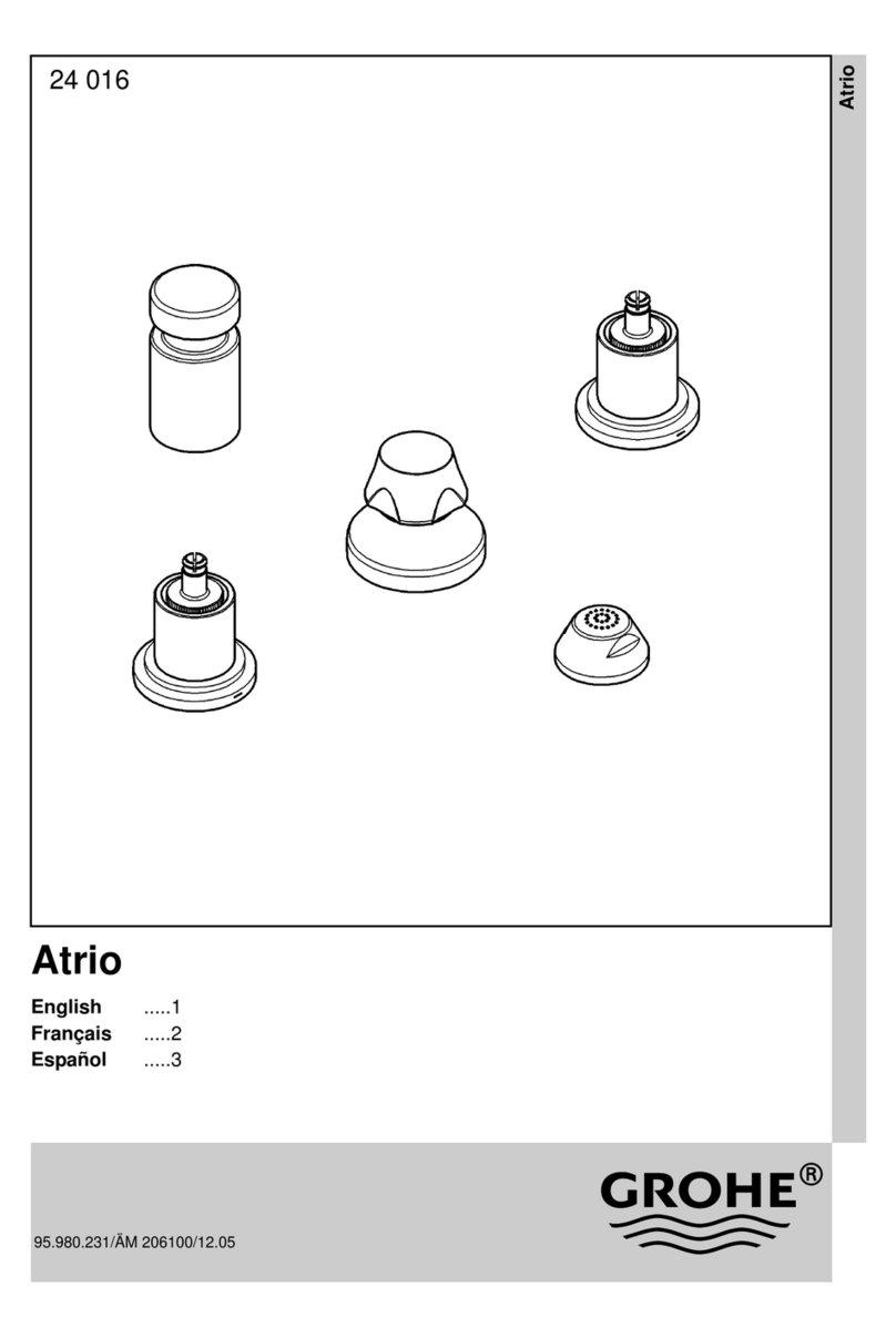
  9. Grohe Atrio 45 998 User manual

Grohe Atrio 45 998 User manual

English .....1
Français .....2
Español .....3
Design & Quality Engineering GROHE Germany
Atrio
Atrio
96.753.031/ÄM 214392/01.09
45 998
English .....1
Français .....1
Español .....2
I
S.v.p remettre cette instruction à l'utilisateur de la robinetterie!
Entregue estas instrucciones al usario final de la grifería!
Please pass these instructions on to the end user of the fitting!
45 998
II
1
5mm
A
B
2
C
D
E
F
3
G
H
4
J
15mm
5
C
K
1
English
Français
Applications
Operation possible in conjunction with: Pressurized storage
heaters, thermally and hydraulically-controlled instantaneous
heaters. Operation with unpressurized storage heaters
(displacement water heaters) is not possible.
Specifications
• Flow pressure
-min. 7.25psi
- recommended 14.5 - 72.5 psi
- greater than 72.5 psi, fit pressure reducing valve
• Max. operating pressure 145 psi
• Test pressure 232 psi
• Temperature
- max. (hot water inlet) 176 °F
• Water connection cold - right
hot - from below
Installation
See fold-out page II, Figs. [1] to [5].
Refer to the dimensional drawing on fold-out page I.
Install built-in mixer housing with symbol facing the
bath side.
1.Remove lid (A) of fitting template (B) and remove fitting
template using a 5mm allen key, see Fig. [1].
2.Drill 25/64" holes for plugs (E), and position plate (C) and
built-in mixer housing (D), see Fig. [2].
3.Insert plugs (E), tightenscrews (F) with supplied wrench and
connect pipes to built-in mixer housing, see Figs. [2] and [3].
Important note
The cold water supply must be connected on the right
(blue marking on housing) and the hot water supply on the
left (red marking on housing), as viewed from the operating
position.
Open hot and cold water supply and check that
connections are watertight.
Flush piping system prior and after installation of faucet
thoroughly, see Figs. [3] and [4].
1.Close the hot and cold water supply.
2.Remove screw plug (G) or (H), see Fig. [3].
3.Screw in flushing plug (J), see Fig. [4].
4.Open the hot and cold water supply and flush the pipes
thoroughly.
5.Close the hot and cold water supply and remove flushing
plug (J).
6.Screw in screw plug (G) or (H).
7.Install fitting template (B) and fit lid (A).
The fitting depth from the lower edge of the plate (C) to the
finished floor surface (K) must be between 3 1/8" and 6 5/16",
see Fig. [5].
Note: Do not cut fitting template prior to final installation.
Domaine d'application
Utilisation possible avec accumulateurs sous pression,
chauffe-eau instantanés à commande thermique et
hydraulique. Un fonctionnement avec des accumulateurs sans
pression (chauffe-eau à écoulement libre) n'est pas possible!
Caractéristiques techniques
• Pression dynamique
- mini. 0.5 bar
- recommandée 1 - 5 bar
- supérieure à 5 bar, mise en place d'un réducteur
de pression
• Pression de service maxi. 10 bar
• Pression d’épreuve 16 bar
• Température
- maxi. (admission d'eau chaude) 80 °C
• Raccord d'eau froide - à droite
chaude - par le bas
Installation
Voir volet II, fig. [1] à [5].
Tenir compte de la cote du schéma sur le volet I.
Monter le corps à encastrer, symbole orienté vers le
côté baignoire.
1.Retirer le cache (A) du gabarit de montage (B) et dévisser le
gabarit avec une clé Allen de 5mm, voir fig. [1].
2.Percer des trous pour les chevilles (E) de 10mmet insérer la
plaque (C) et le corps encastré (D), voir fig. [2].
3.Insérer les chevilles (E) et serrer les vis (F) avec la clé
fournie et brancher les conduites au corps encastré, voir
fig. [2] et [3].
Attention!
Brancher l'eau froide à droite (repère bleu sur le boîtier)
et l'eau chaude à gauche (repère rouge sur le boîtier).
Ouvrir l'arrivée d'eau froide et d'eau chaude et vérifier
l'étanchéité des raccordements.
Bien rincer les canalisations avant et après l’installation,
voir fig. [3] et [4].
1.Ouvrir l'arrivée d'eau froide et d'eau chaude.
2.Dévisser le bouchon fileté (G) ou (H), voir fig. [3].
3.Visser le bouchon de rinçage (J), voir fig. [4].
4.Ouvrir l'arrivée d'eau froide et d'eau chaude et bien purger
les tuyauteries.
5.Fermer les arrivées d’eau chaude et d’eau froide et enlever
les bouchons (J).
6.Visser le bouchon fileté (G) ou (H).
7.Placer le gabarit de montage (B) et le cache (A).
La profondeur de montage du bord inférieur de la plaque (C)
jusqu'à la surface du sol préparé (K) doit se situer entre 80mm
et 160mm, voir fig. [5].
Remarque: Ne pas raccourcir le gabarit de montage avant
l'installation finale.
2
Español
Campo de aplicación
Es posible el funcionamiento con: acumuladores de presión,
calentadores instantáneos con control térmico e hidráulico.
No es posible el funcionamiento con acumuladores sin presión
(calentadores de agua sin presión).
Datos técnicos
•Presión
- mín. 7.25 psi
- recomendada 14.5 - 72.5 psi
- si la presión es superior a 72.5 psi, se deberá
instalar una válvula reductora de presión
• Presión de utilización máx. 145 psi
• Presión de verificación 232 psi
• Temperatura
- máx. (entrada del agua caliente) 176 °F
• Acometida del agua fría - a la derecha
caliente - desde abajo
Instalación
Véase la página desplegable II, figs. [1] a [5].
Respetar el croquis de la página desplegable I.
Montar la batería empotrable con el símbolo hacia el
lado de la bañera.
1.Retirar la tapa (A) de la plantilla de montaje (B) y
desenroscarla con una llave de macho hexagonal de 5mm,
véase la fig. [1].
2.Realizar taladros para tacos (E) de 25/64" y colocar la
placa (C) y la batería empotrable (D), véase la fig. [2].
3.Colocar los tacos (E), apretar los tornillos (F) con la llave
adjunta y conectar las tuberías a la batería empotrable,
véanse las figs. [2] y [3].
¡Importante!
La acometida del agua fría debe conectarse a la derecha
(marca azul en la carcasa) y la del agua caliente debe
conectarse a la izquierda (marca roja en la carcasa).
Abrir las llaves de paso del agua fría y del agua caliente y
comprobar la estanqueidad de las conexiones.
¡Purgar a fondo el sistema de tuberías antes y después
de la instalación, véanse las figs. [3] y [4].
1.Cerrar las llaves de paso del agua fría y del agua caliente.
2.Desenroscar el tornillo de cierre (G) o (H), véase la fig. [3].
3.Enroscar el tapón de purga (J), véase la fig. [4].
4.Abrir las llaves de paso del agua fría y del agua caliente y
purgar a fondo las tuberías.
5.Cerrar las llaves de paso del agua fría y del agua caliente y
quitar los tapones de purga (J).
6.Enroscar el tapón roscado (G) o (H).
7.Instalar la plantilla de montaje (B) y colocar la tapa (A).
La profundidad de montaje desde el borde inferior de la
placa (C) hasta la superficie acabada del suelo (K) debe estar
entre 3 1/8" y 6 5/16", véase la fig. [5].
Nota: No acortar la plantilla de montaje antes de proceder a la
instalación de acabado.
Grohe Canada Inc.
1230 Lakeshore Road East
Mississauga, Ontario
Canada, L5E 1E9
Technical Services
Services Techniques
Phone/Tél: 905/271-2929
Fax/Télécopieur: 905/271-9494
Grohe America Inc.
241 Covington Drive
Bloomingdale, IL
60108
U.S.A.
Technical Services
Phone: 630/582-7711
Fax: 630/582-7722
www.grohe.com

Other Grohe Plumbing Product manuals

Grohe EUROECO COSMOPOLITAN E + POWERBOX 36 384 User manual

Grohe

Grohe EUROECO COSMOPOLITAN E + POWERBOX 36 384 User manual

Grohe Get 23 227 User manual

Grohe

Grohe Get 23 227 User manual

Grohe 23 429 User manual

Grohe

Grohe 23 429 User manual

Grohe 32 467 User manual

Grohe

Grohe 32 467 User manual

Grohe Essence 32 105 User manual

Grohe

Grohe Essence 32 105 User manual

Grohe Atrio 34 061 User manual

Grohe

Grohe Atrio 34 061 User manual

Grohe QUICKFIX User manual

Grohe

Grohe QUICKFIX User manual

Grohe Allure 34 236 User manual

Grohe

Grohe Allure 34 236 User manual

Grohe EUROSMART 32 642 User manual

Grohe

Grohe EUROSMART 32 642 User manual

Grohe BLUE 31 312 User manual

Grohe

Grohe BLUE 31 312 User manual

Grohe Eurodisc 33 772 User manual

Grohe

Grohe Eurodisc 33 772 User manual

Grohe Ondus 36 047 User manual

Grohe

Grohe Ondus 36 047 User manual

Grohe BRIDGEFORD 33 870 User manual

Grohe

Grohe BRIDGEFORD 33 870 User manual

Grohe Allure E User manual

Grohe

Grohe Allure E User manual

Grohe Essence 32 216 User manual

Grohe

Grohe Essence 32 216 User manual

Grohe BAU COSMOPOLITAN E 36 466 User manual

Grohe

Grohe BAU COSMOPOLITAN E 36 466 User manual

Grohe 31 347 User manual

Grohe

Grohe 31 347 User manual

Grohe EUROPLUS 20 302 User manual

Grohe

Grohe EUROPLUS 20 302 User manual

Grohe Essence 32 171 User manual

Grohe

Grohe Essence 32 171 User manual

Grohe Bridgeford 20135 User manual

Grohe

Grohe Bridgeford 20135 User manual

Grohe ESSENCE E 36 447 User manual

Grohe

Grohe ESSENCE E 36 447 User manual

Grohe Grohtherm 1000 34 334 User manual

Grohe

Grohe Grohtherm 1000 34 334 User manual

Grohe GROHTHERM 3000 COSMOPOLITAN 19 568 User manual

Grohe

Grohe GROHTHERM 3000 COSMOPOLITAN 19 568 User manual

Grohe Eurodusc 33190 User manual

Grohe

Grohe Eurodusc 33190 User manual

Popular Plumbing Product manuals by other brands

Carron Phoenix SAVONA Fitting Instructions & Contents List

Carron Phoenix

Carron Phoenix SAVONA Fitting Instructions & Contents List

Lefroy Brooks X1-1056 Installation instructions manual

Lefroy Brooks

Lefroy Brooks X1-1056 Installation instructions manual

ESS Easy Drain Dryphon upgrade set 30 Installation advice

ESS

ESS Easy Drain Dryphon upgrade set 30 Installation advice

Kohler 8002A Installation and user guide

Kohler

Kohler 8002A Installation and user guide

Sanela SLU 04HT17 Instructions for use

Sanela

Sanela SLU 04HT17 Instructions for use

Pfister Brookwood 34 Series manual

Pfister

Pfister Brookwood 34 Series manual

Symmons Dia SLS3522PP Operation & maintenance manual

Symmons

Symmons Dia SLS3522PP Operation & maintenance manual

JADO Borma 014 132 Series installation instructions

JADO

JADO Borma 014 132 Series installation instructions

Kessel Megastop 44700.66 manual

Kessel

Kessel Megastop 44700.66 manual

Kohler K-997 quick start guide

Kohler

Kohler K-997 quick start guide

Signature Hardware PAGOSA 928335 installation manual

Signature Hardware

Signature Hardware PAGOSA 928335 installation manual

Symmons Sereno SK2302PD Operation & maintenance manual

Symmons

Symmons Sereno SK2302PD Operation & maintenance manual

VIGO FERRARA VG06080 installation guide

VIGO

VIGO FERRARA VG06080 installation guide

JNH MG417HB Assembly instruction

JNH

JNH MG417HB Assembly instruction

Clou New Flush 3.1 CL/03.13431 installation instructions

Clou

Clou New Flush 3.1 CL/03.13431 installation instructions

MAAX Utile installation instructions

MAAX

MAAX Utile installation instructions

Purmo OPTIMO 500E ECO Installation & operating manual

Purmo

Purmo OPTIMO 500E ECO Installation & operating manual

Sanela SLU 92NP Instructions for use

Sanela

Sanela SLU 92NP Instructions for use

manuals.online logo
manuals.online logoBrands
  • About & Mission
  • Contact us
  • Privacy Policy
  • Terms and Conditions

Copyright 2025 Manuals.Online. All Rights Reserved.