Grove Crane GMK6350 User manual

product
guide
features
•51-197 ft. (15.5-60m) 5-section full power
MEGAFORM™ boom
•36-62 ft. (11-19m) telescoping offsettable
swingaway extension
•69-200 ft. (21-61m) luffing jib
•MEGALIFT™ main boom attachment
•220,400 lb. (100 Tonnes) counterweight with
hydraulic removal system
•MEGATRAK™ suspension
GMK6350
All Terrain Crane
contents
Features 2
Specifications 3
Dimensions 5
Counterweight 6
Travel Proposal 7
Working Range 8
Main Boom and
Swingaway Charts 9
Working Range MEGALIFT 11
MEGALIFT charts 12
Working Range w/inserts 13
Swingaway Charts
w/one or two inserts 14
Working Range Luffing 15
Luffing Charts 16
Overview 22
www.manitowoc.com

2
GMK6350
features
Grove GMK cranes
incorporate a truly
independent suspension
system known as
MEGATRAK™ which
allows all wheels to remain
on the ground at all times
so that stresses and
weights are not continually
transferred between axles.
Controlled from the cab,
the suspension can be
raised or lowered (front-to-
back and side-to-side) or
automatically levelled for
highway travel.
While the operator is concentrating on the
lift, ECOS (Electronic Crane Operating
System) is busy monitoring and controlling
all of the principle crane functions and
providing exact telescoping status on its
fully graphic in cab display.
Monitoring the lifting condition of the crane at all times, EKS4 works
together with, but independently of the ECOS as a complete command
and control system, or separately as a load moment indicator.
Continually running fault analysis, the system advises service codes
which can be transmitted to any Grove service center,allowing fast
accurate investigation and recommendation.
The proven “U” shaped MEGAFORM™
boom design provides a natural cradling
position for boom sections which
eliminates stiffeners-thus reducing
weight and increasing capacity. Large
wear pads provide superior boom
alignment when telescoping and allows
an excellent transition of weights
between sections.
The unique TWIN-LOCK™ boom
pinning system automatically pins the
sections in position using two
horizontal large diameter pins, which
increases security. A single telescope
cylinder inside the boom reduces
weight which has been used
elsewhere to strengthen the machine.

Superstructure
3
GMK6350
specifications
Boom
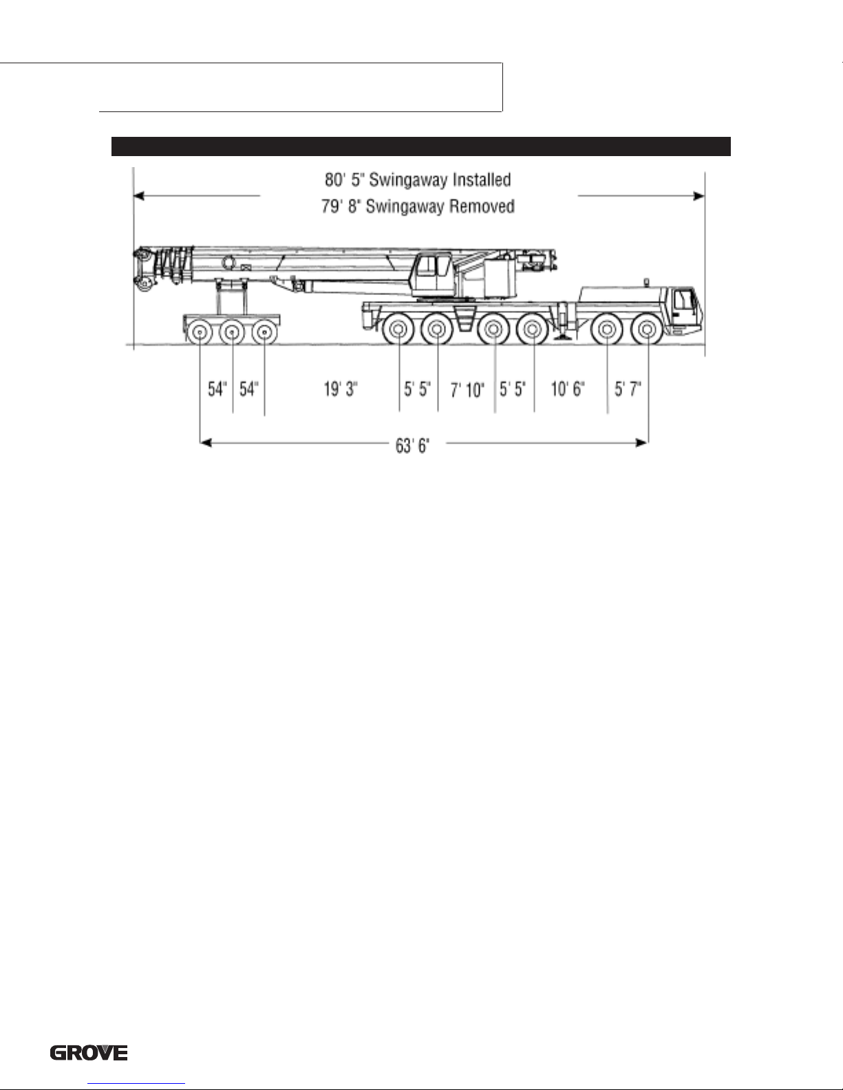
51 ft. - 197 ft. (15.5 m - 60 m) five section, full power
MEGAFORM™boom with patented TWIN-LOCK™boom pinning
system. Maximum tip height: 207 ft. (63 m).
Boom Elevation
Single lift cylinder with safety valve provides boom angle from -
1.5° to +82°.
*Telescopic Swingaway Extension
36ft. - 62 ft. (11m-19 m) telescoping offsettable swingaway
extension. Offsettable at 5° and 30°.
Lattice Jib
Luffing Jib is a lattice design with lengths of 69 ft. -200 ft. (21 m -
61m) in sections of 26 ft. (8 m). The luffing jib converts to a fixed
offset lattice jib using an offset angle adapter and provides
lengths of 62 ft. - 194 ft. (19 m - 59 m) offsettable at 3° and 25°.
MEGALIFT™ Attachment-Main Boom
Consists of a mast, pendant lines, and hydraulic tensioning
winch to support the main boom during lifting operations. Load
charts available for main boom only as optional equipment.
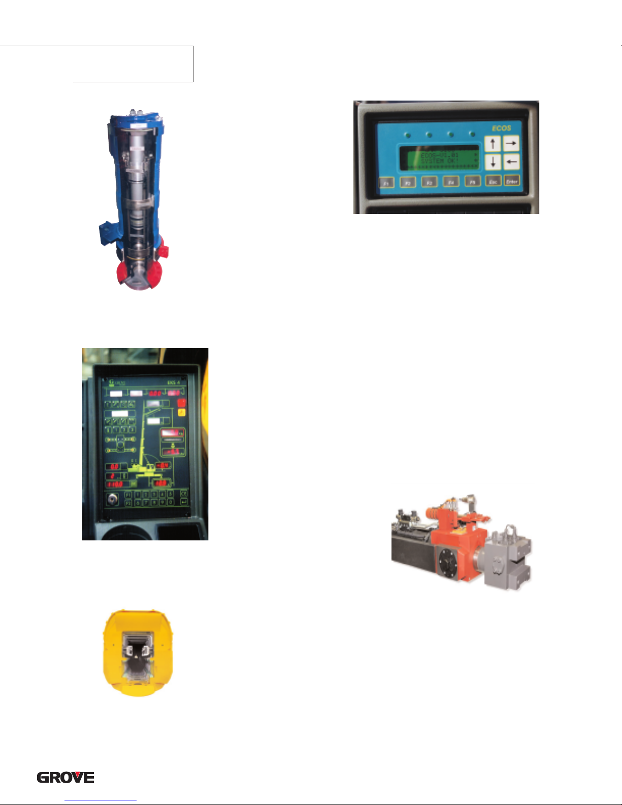
Load Moment & Anti-Two Block System
Load moment and anti-two block system with audio/visual
warning and control lever lockout provides electronic display of
boom angle, length, radius, tip height, relative load moment,
maximum permissible load, load indication and warning of
impending two-block condition.
Cab
All aluminum construction cab is tiltable (approximately 20°) and
includes safety glass and adjustable operator’s seat with
hydraulic suspension. Other features include engine dependent
hot water heater, armrest integrated crane controls, and
ergonomically arranged instrumentation.
Swing
3axial piston fixed displacement motors provide swing speed of
0-1.6 RPM thru planetary gear box. Also provided is a spring
applied, hydraulically released automatic swing brake with foot
operated release for free swing.
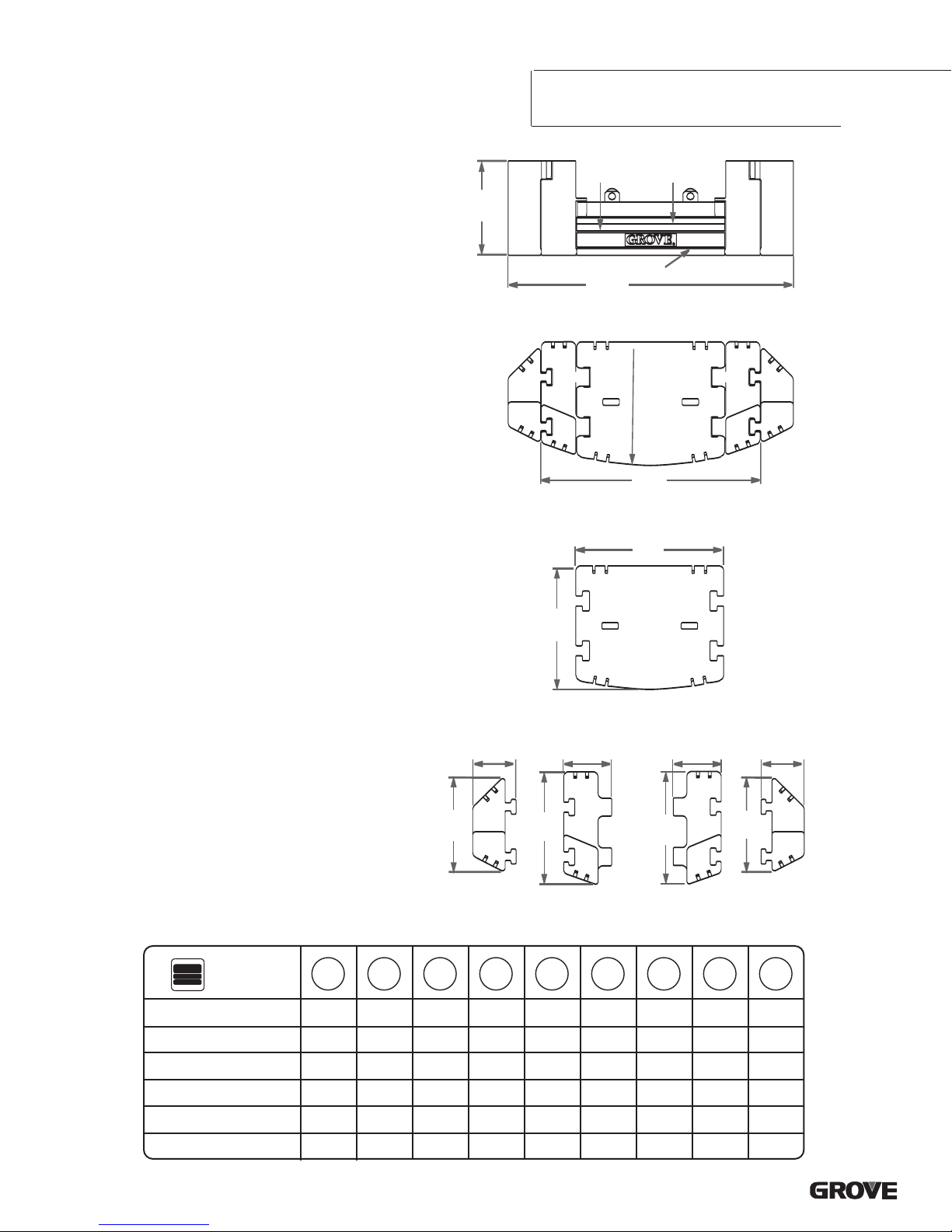
Counterweight
220,400 lbs. (100 Tonnes) consisting of various sections with
hydraulic installation/removal system (see counterweight
configuration on page 17).
Engine
Mercedes-Benz OM906LA, diesel, 6 cylinders, water cooled,
turbocharged, 275 HP (205 kW) at 1800 rpm.
Max. torque: 811 ft./lbs. (1100 Nm) at 1300 rpm.
Engine emission: EUROMOT/EPA/CARB.
Fuel Tank Capacity
87 gal. (330 L).
Hydraulic System
4separate circuits, 3 axial piston variable displacement pumps
with electronic power limiting control and 1 axial piston variable
displacement pump for slewing. Standard thermostatically
controlled oil cooler keeps oil at optimum operating temperature.
Tank capacity: 322 gal. (1220 L)
Control System
Full electronic control of all crane movements is accomplished
using electrical control levers with automatic reset to zero.
Controls are integrated with the LMI and engine management
system by CAN-BUS.
Hoist
Main and auxiliaryhoist are powered by axial piston variable
displacement motor with planetary gear and brake. “Thumb-
thumper” hoist drum rotation indicator alerts operator of hoist
movement.
Main Auxiliary
Line length: 984 ft. 1,378 ft.
(300 m) (420 m)
Rope diameter: 24 mm 24 mm
Line speed: 460 ft./min. 426 ft./min.
(140 m/min) (130 m/min)
Line pull: 24,700 lbs. 24,700 lbs.
(110 kN) (110 kN)
Electrical System
24 V system with three-phase alternator 28 V/80 A, 2 batteries 12
V/170 Ah.
*Optional Equipment
*Engine-independent diesel heater,with engine pre-heater
*Second spotlight
*Stereo/CD player
*Air Conditioning
*Stainless steel exhaust system
*MEGALIFT attachment
*Engine independent propane cab heater
*Auxiliaryboom nose
*Boom mounted work lights
*Aircraft warning light
*24 hr. timer for diesel heater
*Denotes optional equipment
Boom
Boom Elevation
Extension
Extension
Boom
Load Moment
&Anti-Two
Block System
Cab
Engine
Fuel
Tank
Capacity
Defined Arc
Counterweight
Hydraulic System
Crane
Functions
Hoist
Electrical System

4
GMK6350
specifications
Chassis
Box-type, torsion resistant frame is fabricated from high-strength
steel.
Outrigger System
Hydraulic two-stage outrigger beams are extended by a single
hydraulic cylinder and two cables. Outriggers can adjust to two
positions:
Fully extended (100%) - 27' 11" (8.5 m)
Partially extended (50%) - 19' 8" (6 m)
Four 29.5 in. x 32 in. (750 mm x 810 mm), self stowing, steel
outrigger pads provide rigid lifting base. Outrigger controls are
located on both sides of the carrier. An electronic level indicator
is located next to each outrigger control box.
Engine
Mercedes-Benz OM502LA, diesel, 8 cylinders, water-cooled,
turbocharged, 563 HP (420 kW) at 1800 rpm.
Max. torque: 1991 ft./lbs. (2700 Nm) at 1080 rpm.
Engine emission: EPA/CARB.
Fuel Tank Capacity
132 gal. (500 L).
Transmission
Allison automatic CLT755, 5 forward and 1 reverse speed.
Transfer case with 2 speeds and inter-axle differential lock.
Drive/Steer
12 x 6 x 12.
Axles
6axles. 1, 2, 4 and 5 are drive/steer. Axles 3 and 6 are steer
only.
Suspension
GROVE GMK6350 features the Grove exclusive MEGATRAK™
suspension. This revolutionarydesign features an independent
hydropneumatic system with hydraulic lockout acting on all
wheels. The suspension can be raised 6-1/2" (170 mm) or
lowered 5" (130 mm) both longitudinally and transversely and
features an automatic leveling system for on-highway travel.
Tires
12 tires, 16.00 R25 (vehicle width 9 ft. 10 in.)
Carrier
Steering
Dual circuit steering system is hydraulic power assisted with a
transfer case mounted, ground driven, emergency steering
pump. Axles 1, 2, 3, 5 and 6 steer on highway. Separate steering
of the 4th, 5th and 6th axle for all wheel steer and crab-steer is
controlled by an electric rocker switch.
Brakes
Adual circuit air system operates on all wheels with a spring-
applied, air released parking brake acting on axles 2, 4, 5 and 6.
An air dryer is fitted to remove moisture from the air system.
Engine compression brake is standard.
Cab
Two-man, aluminum construction driver’s cab includes the
following features: safety glass; driver and passenger seats with
hydraulic suspension, engine-dependent hot water heater,
complete instrumentation and driving controls.
Electrical System
24 V system with three-phase alternator 28 V/80 A,
2batteries 12 V/170 Ah.
Maximum Speed
48 mph (77km/h) with 16.00/20.5 tires.
Gradeability (theoretical)
46% with 20.5 R25 tires.
Miscellaneous Standard Equipment
Boom removal kit; trailing boom kit (less dolly); additional
hydraulic oil cooler; removable rear outrigger box; flashing
amber warning light on carrier cab; working light; tool kit; fire
extinguisher; radio cassette in carrier cab.
*Optional Equipment
*12 x 8 x 12
*Electric driveline retarder
*20.5 tires
*Outrigger pressure measurement devices
*Engine-independent hot water heater, with engine pre-heater
*Stainless steel exhaust system
*Trailing boom “boost” weight transfer kit
*Air conditioning
*Spare tire and wheel
*Worklights for outriggers
*Engine independent propane cab heater
*Rear mounted stowage box
*Denotes optional equipment
Frame
Outriggers
Engine
Fuel
Tank
Capacity
Transmission
Steering
Axles
Suspension
Tires
Steering
Brakes
Cab
Electrical System
Speed
Grade

5
GMK6350
dimensions
R 22' 10" (6950)
Ra 17' 7" (5355)
R 20' 10"(6345)
Ra 35' 6" (10 840)
Ra 33' 7" (10 240)
R47' 3" (14 410)
Ra 42' 10" (13 050)
R 15' 9" (4800)
16' 3"
(4960) 28' 6"
(8700)
12' 3"
(3740)
19' 8"
(6000)
18' 10"
(5740)
14' 5"
(4400)
10'
(3070)
11'
(3360)
17' 6"
(5340)
28' 6"
(8700)
9'
(2740)
R38' 8" (11 790)
Ra 38' 6" (11 740)
R 43' 7" (13 280)
R 38' 10" (11 850)
27' 11"
(8500)
R 18' 4" (5580)
R 39' 8" (12 110)
Ra 37' 1" (11 310)
1' 3"
(375)
5' 3"
(1610)
2' 9"
(850)
1'
(310)
7' 10-1/2"
(2400)
5' 7"
(1700) 5' 5"
(1650)
1' 4"
(400) 5' 5"
(1650)
4' 11
"
(1500) 2' 10"
(870)
13'-2"
(4013)
+ 6-1/2" (170)
- 5" (130)
7' 9"
(2370)
50' 5"
(15 370) 59' 3"
(18 050)
10' 6"
(3200)
7' 10-1/2"
(2400)
8' 6"
(2600)
15' 6"
(4730)
50' 9"
(15 460)
64' 7"
(19 680)
16
°
14
°
BASIC WEIGHTS (LBS.) Axles 1 & 2 Axles 3 - 6 Total
Mercedes Power, 12x6, 20.5 R25 Tires,
2nd Hydraulic Oil Cooler,Brackets for swingaway 50,781107,969 158,750
Additions:
12 x 8 x 12 in lieu 965 -(105) 860
Outrigger Pads - 772 772
Removable rear outrigger box option -(1,225) 3,430 2,205
Auxiliary Hoist -(5,365) 11,450 6,085
Swingaway 6,860 -(1,525) 5,335
Spare Wheel 20.5 with stowage -(590) 1,400 810
Spare Wheel 16.00 with stowage -(520) 1,240 720
Spare Wheel 14.00 with stowage -(425) 1
,010585
Fixed MEGALIFT brackets w/o winch 653 lbs. -123 lbs. 530 lbs.
Fixed bracket for MEGALIFT winch 119 lbs. 212 lbs. 331 lbs.
Bolted parts for MEGALIFT 119 lbs. 212 lbs. 331 lbs.
MEGALIFT winch 6,257 lbs. 5,736 lbs. 11
,993 lbs.
Removal:
Front Outrigger Beams & Jacks -(3,380) -(1,980) -(5,360)
Rear Outrigger Beams & Jacks 3,730 -(9,650) -(5,920)
Outrigger Box (must add weight above for option) 6,750 -(17,550) -(10,800)
Boom Assembly (minus lift cylinder) -(34,750) -(23,175) -(57,925)
Telescope Sections 1-4 -(27,900) -(15,860) -(43,760)
Lift Cylinder -(2,250) -(3,400) -(5,650)
16.00 R25 Tires in lieu -(370) -(740) -(1,110)
14.00 R25 Tires in lieu -(900) -(1,800) -(2,700)
Note: ( ) Reference dimensions in mm

6
GMK6350
trailing boom proposal
Trailing Boom
54" 54" 19' 3" 5' 5" 7' 10" 5' 5" 10' 6" 5' 7"
63' 6"
79' 8" Swingaway Removed
80' 5" Swingaway Installed
FRONT 2 AXLES
34,787 LBS.
REAR 4 AXLES
91,299 LBS.
DOLLY
55,316 LBS.
G.V.W.: 181,402 LBS.
UNIT EQUIPPED AS FOLLOWS:
Mercedes engines carrier and superstructure, outrigger pads in place, frame equipped
for removable outrigger box, rear box in place, main & auxiliary hoist with rope,
swingaway on boom, 3 axle boom dolly (7,600 LBS.), 16.0 tires, counterweight
removed. 12 x 6 x 12 drive.
Note: Weights may vary 3% due to manufacturing tolerances.
Weight effects:
Component Dolly Rear Axles Front Axles Gross
Remove rear outrigger box 0 -17,555 lbs. +6,753 lbs. -10,802 lbs.
Remove front outrigger beams 0 -1,980 lbs. -3,377 lbs. -5,357 lbs.
Remove rear outrigger beams 0 -9,652 lbs. +3,732 lbs. -5,919 lbs.
Remove auxiliary hoist with rope 0 -2,134 lbs. -3,951 lbs. -6,085 lbs.
Remove swingaway -5,205 lbs. +99 lbs. +35 lbs. -5,071 lbs.
Add 12 x 8 x 12 Drive 0 -106 lbs. +966 lbs. +860 lbs.
Fixed MEGALIFT brackets w/o winch 547 lbs. -13 lbs. -4lbs. 529 lbs.
Fixed bracket for MEGALIFT winch 170 lbs. 119lbs. 42lbs. 331lbs.
Bolted parts for MEGALIFT 170 lbs. 119lbs. 42lbs. 331lbs.
MEGALIFT winch 7,299 lbs. 3,468 lbs. 1,224 lbs. 11,993 lbs.
THIS ILLUSTRATION IS ONLY A GUIDE. CONSULT FACTORY FOR SPECIFIC DETAILS.

7
GMK6350
counterweight
758
6
1
2
3A3B
4
R 18' 4" (5580)
1
2
3A
3B
4
2' 10"
(870)
3' 2"
(965)
2' 10"
(870)
3' 2"
(965)
7
568
6' 3"
(1900)
18' 10"
(5740)
14' 5"
(4400)
8' 2"
(2490)
9' 9"
(2980)
6' 1"
(1860)
7' 5"
(2270) 7' 5"
(2270)
6' 1"
(1860)
Counterweight
17,600 lbs.
48,500 lbs.
79,300 lbs.
110,200 lbs.
176,300 lbs.
220,400 lbs.
1. 17,600 lbs. (8 Tonnes)
2. 30,900 lbs. (14 Tonnes)
3A. 15,450 lbs. (7 Tonnes)
3B. 15,450 lbs. (7 Tonnes)
4. 30,900 lbs. (14 Tonnes)
5. 33,000 lbs. (15 Tonnes)
6. 33,000 lbs. (15 Tonnes)
7.22,050 lbs. (10 Tonnes)
8. 22,050 lbs. (10 Tonnes)
12
XXXXXXX
XXXXXXX
XXXX
XX
X
X
Note: ( ) Reference dimensions in mm
X
XX
X
XX
3A3B45678

8
GMK6350
working range
51'-197' main boom
THIS CHART IS ONLY A GUIDE AND SHOULD NOT BE USED TO OPERATE THE CRANE.
The individual crane’s load chart, operating instructions and other instructional plates must be read and understood prior to operating the crane.
280
270
260
250
240
230
220
210
200
190
180
170
160
150
140
130
120
110
100
90
80
70
60
50
40
30
20
10
240 230 220 210 200 190180 170 160 150 140130 120 110 100 90 80 70 6050 40 30 20 10 0
+62 FT.197 FT.
+36 FT.
160 FT.124 FT.87 FT. 51 FT.
82˚
Height from the ground in feet
Operating radius in feet from axis of rotation
R [ft]
30
o
5
o

9
GMK6350
load charts
THIS CHART IS ONLY A GUIDE AND SHOULD NOT BE USED TO OPERATE THE CRANE.
The individual crane’s load chart, operating instructions and other instructional plates must be read and understood prior to operating the crane.
Boom
Counterweight
Outriggers
Defined Arc
51-197 ft.
(15.5-60.0 m)
220,400 lb.
(100 Tonnes)
100%
27' 11" Spread
360o
Pounds (thousands)
Boom
Radius
Boom Extension
Feet 51* 51 69 87 106 124 142 160 178 197
8700.0†
10 542.0 466.0 422.0 342.0
15 412.0 370.0 366.0 342.0 242.0
20 332.0 302.0 302.0 300.0 242.0 185.0 139.0
25 266.0 254.0 258.0 254.0 242.0 185.0 139.0 106.0
30 219.0 218.0 222.0 222.0 220.0 185.0 139.0 106.0 78.0 66.0
35 185.0 185.0 188.0 188.0 187.0 174.0 137.0 106.0 78.0 66.0
40 162.0 163.0 161.0 161.0 126.0 106.0 78.0 66.0
45 142.0 143.0 141.0 144.0 116.0 102.0 78.0 66.0
50 126.0 126.0 128.0 128.0 106.0 95.0 78.0 66.0
55 113.0 113.0 116.0 114.0 98.0 88.0 78.0 66.0
60 102.0 105.0 103.0 91.0 82.0 75.0 66.0
65 92.0 95.0 93.0 84.0 76.0 70.0 65.0
70 85.0 86.0 85.0 78.0 71.0 66.0 62.0
75 79.0 77.0 73.0 66.0 62.0 59.0
80 72.0 70.0 67.0 62.0 58.0 56.0
85 67.0 65.0 64.0 58.0 54.0 52.0
90 62.0 60.0 61.0 54.0 50.0 49.0
95 55.0 57.0 50.0 47.0 46.0
100 51.0 53.0 48.0 45.0 43.4
105 47.0 50.0 45.0 42.4 41.0
110 45.0 46.0 42.4 40.2 39.0
115 43.2 40.4 38.2 37.0
120 40.6 38.6 36.2 35.2
125 37.0 34.4 33.6
130 34.6 32.6 32.0
135 33.4 31.2 30.0
140 32.4 30.0 27.8
145 28.8 26.0
150 27.2 24.8
155 25.6 23.8
160 24.4 22.6
165 21.8
170 20.6
175 19.2
180 17.2
Feet 51 69 87 106 124 142 160 178 197
10 446.0 422.0 342.0
15 352.0 352.0 342.0 242.0
20 278.0 282.0 282.0 242.0 185.0 139.0
25 222.0 224.0 224.0 224.0 185.0 139.0 106.0
30 180.0 183.0 183.0 182.0 182.0 139.0 106.0 78.0 66.0
35 147.0 150.0 151.0 155.0 150.0 137.0 106.0 78.0 66.0
40 129.0 131.0 130.0 126.0 118.0 106.0 78.0 66.0
45 111.0 113.0 112.0 108.0 102.0 97.0 78.0 66.0
50 95.0 97.0 97.0 94.0 94.0 87.0 78.0 66.0
55 81.0 83.0 83.0 82.0 83.0 79.0 73.0 66.0
60 73.0 72.0 75.0 73.0 70.0 68.0 66.0
65 64.0 63.0 66.0 64.0 64.0 63.0 59.0
70 57.0 59.0 59.0 57.0 58.0 56.0 53.0
75 54.0 53.0 52.0 52.0 51.0 48.0
80 48.0 48.0 48.0 47.0 46.0 43.0
85 43.8 42.8 43.6 42.6 41.2 39.0
90 39.6 38.8 39.6 38.4 37.0 35.4
95 36.2 36.0 34.8 33.4 31.8
100 33.0 32.8 31.6 30.2 28.6
105 30.0 29.8 28.8 27.4 25.6
110 27.6 27.4 26.2 24.8 23.2
115 25.0 23.8 22.6 20.8
120 23.0 21.8 20.4 18.8
125 19.8 18.6 16.8
130 18.2 16.8 15.0
135 16.6 15.2 13.4
140 15.0 13.8 12.0
145 12.4 10.6
150 11.2 9.4
155 10.0 8.2
160 9.0 7.0
165 6.0
170 5.0
175 4.2
Boom
Counterweight
Outriggers
Defined Arc
51-197 ft.
(15.5-60.0 m)
110.200 lb.
(50 Tonnes)
100%
27' 11" Spread
360o
Pounds (thousands)
Boom
Radius
Boom Extension
*Over rear only, 28’6” x 19’8” outrigger base. Lifting capacities greater than 425,000 lbs require additional equipment. † 700,00 lbs is a comparative rating
Lifting capacities greater than 425,000 lbs require additional equipment. Note: Above chart is available with reduced outriggers

179 FT MAIN BOOM 197 FT MAIN BOOM
36 FT 62 FT 36 FT 62 FT
Feet 5° 30° 5° 30° 5° 30° 5° 30°
40 45.0 19.0 38.8 18.4
45 43.6 18.4 38.8 18.2
50 42.8 32.6 17.6 38.8 30.8 17.6
55 42.0 31.8 17.0 38.4 30.4 17.0
60 41.2 31.0 16.2 37.8 30.2 16.2
65 40.4 30.4 15.6 37.4 29.8 15.8
70 39.6 29.8 15.0 10.0 36.8 29.6 15.2
75 39.0 29.2 14.4 9.8 36.4 29.2 14.6 9.8
80 38.2 28.6 14.0 9.6 35.8 28.6 14.2 9.6
85 37.6 28.0 13.6 9.4 35.4 28.2 13.8 9.4
90 36.8 27.6 13.0 9.2 34.4 27.6 13.2 9.4
95 36.0 26.8 12.6 9.2 34.0 27.0 13.0 9.2
100 35.2 25.8 12.2 9.0 34.0 26.0 12.6 9.0
105 34.4 24.8 11.8 8.8 33.6 25.0 12.2 8.8
110 33.4 24.6 11.6 8.6 33.0 24.6 11.8 8.8
115 32.6 24.2 11.2 8.6 32.6 24.4 11.6 8.6
120 31.6 23.8 11.0 8.4 32.0 24.0 11.2 8.6
125 30.8 23.6 10.6 8.4 31.0 23.8 11.0 8.4
130 30.0 23.4 10.4 8.2 30.2 23.6 10.6 8.4
135 28.6 23.2 10.2 8.2 28.6 23.4 10.4 8.2
140 27.2 23.0 10.0 8.0 26.8 23.0 10.2 8.2
145 25.8 22.8 9.6 8.0 25.2 22.8 10.0 8.0
150 24.6 22.6 9.4 7.8 24.2 22.8 9.8 8.0
155 23.6 22.4 9.2 7.8 23.0 22.6 9.6 7.8
160 22.4 22.2 9.0 7.8 22.2 22.2 9.4 7.8
165 21.0 21.6 8.8 7.6 21.2 21.6 9.2 7.8
170 20.2 20.4 8.8 7.6 20.2 20.8 9.0 7.6
175 19.4 19.8 8.6 7.6 19.0 20.0 8.8 7.6
180 18.8 8.4 7.6 17.8 18.6 8.6 7.6
185 18.2 8.2 7.4 16.6 17.2 8.6 7.6
190 17.4 8.2 7.4 15.4 16.0 8.4 7.6
195 8.0 7.4 14.2 8.2 7.4
200 7.8 7.4 13.2 8.2 7.4
205 7.8 12.4 8.0 7.4
210 7.6 8.0 7.4
215 7.6 7.8 7.4
220 7.6 7.8 7.4
225 7.4 7.6
230 7.6
235 7.4
240 7.4
THIS CHART IS ONL
YAGUIDE AND SHOULD NOTBE USED TOOPERA
TE THE CRANE.
The individual crane’sload chart, operating instructions and other instructional plates must be read and understood prior to operating the crane.
10
GMK6350
load charts
Boom
Extension
Outriggers
Defined Arc
179-197 ft.
(54.4-60.0 m)
36-62 ft.
(11-19 m)
Counterweight
220,400 lb.
(100 Tonnes)
100%
27' 11" Spread
360o
Pounds (thousands)
Boom
Radius
Boom Extension
179 FT MAIN BOOM 197 FT MAIN BOOM
36 FT 62 FT 36 FT 62 FT
Feet 5° 30° 5° 30° 5° 30° 5° 30°
40 45.0 19.0 38.8 18.4
45 43.6 18.4 38.8 18.2
50 42.8 32.6 17.6 38.8 30.8 17.6
55 42.0 31.8 17.0 38.4 30.4 17.0
60 41.2 31.0 16.2 37.8 30.2 16.2
65 40.4 30.4 15.6 37.4 29.8 15.8
70 39.6 29.8 15.0 10.0 36.8 29.6 15.2
75 39.0 29.2 14.4 9.8 36.4 29.2 14.6 9.8
80 38.2 28.6 14.0 9.6 35.8 28.6 14.2 9.6
85 36.8 28.0 13.6 9.4 35.4 28.2 13.8 9.4
90 36.0 27.6 13.0 9.2 33.6 27.6 13.2 9.4
95 33.8 26.8 12.6 9.2 30.6 27.0 13.0 9.2
100 30.8 25.8 12.2 9.0 27.8 26.0 12.6 9.0
105 27.8 24.8 11.8 8.8 25.2 25.0 12.2 8.8
110 25.2 24.6 11.6 8.6 23.0 24.6 11.8 8.8
115 23.0 24.0 11.2 8.6 20.8 23.2 11.6 8.6
120 20.8 22.6 11.0 8.4 18.8 21.0 11.2 8.6
125 18.8 20.6 10.6 8.4 16.8 18.8 11.0 8.4
130 17.0 18.6 10.4 8.2 15.0 17.0 10.6 8.4
135 15.4 17.0 10.2 8.2 13.4 15.2 10.4 8.2
140 14.0 15.4 10.0 8.0 12.0 13.6 10.2 8.2
145 12.6 13.8 9.6 8.0 10.6 12.2 10.0 8.0
150 11.2 12.4 9.4 7.8 9.2 10.8 9.8 8.0
155 10.0 11.2 9.2 7.8 8.0 9.4 9.6 7.8
160 9.0 10.0 9.0 7.8 7.0 8.2 9.4 7.8
165 8.0 8.8 8.8 7.6 6.0 7.0 9.2 7.8
170 7.0 7.8 8.6 7.6 5.0 6.0 8.2 7.6
175 6.0 6.8 8.6 7.6 4.0 5.0 7.2 7.6
180 5.2 8.2 7.6 3.2 4.0 6.4 7.6
185 4.4 7.4 7.4 3.2 5.6 7.2
190 3.6 6.6 7.4 4.8 6.4
195 5.8 7.0 4.0 5.6
200 5.2 6.2 3.4 4.6
205 4.4 2.6 3.8
210 3.8 3.2
215 3.2
220 2.6
Pounds (thousands)
Boom
Radius
Boom Extension
Boom
Extension
Outriggers
Defined Arc
179-197 ft.
(54.4-60.0 m)
36-62 ft.
(11-19 m)
Counterweight
110,200 lb.
(50 Tonnes)
100%
27' 11" Spread
360o

working range – MEGALIFT
11
GMK6350
THIS CHART IS ONLY A GUIDE AND SHOULD NOT BE USED TO OPERATE THE CRANE.
The individual crane’s load chart, operating instructions and other instructional plates must be read and understood prior to operating the crane.
142'-197' MEGAWING lift
0102030405060708090100110120130140150160170180190200
10
20
30
40
50
60
70
80
90
100
110
120
130
140
150
160
170
180
190
200
210
220
230
max 82˚
Operating radius in feet from axis of rotation
Height from the ground in feet
197 FT.
178 FT.
160 FT.
142 FT.

12
GMK6350
load charts
THIS CHART IS ONLY A GUIDE AND SHOULD NOT BE USED TO OPERATE THE CRANE.
The individual crane’s load chart, operating instructions and other instructional plates must be read and understood prior to operating the crane.
Radius
Pounds (thousands)
Extension
Feet 142 160 178 197
20 139.0
25 139.0 106.0
30 139.0 106.0 78.0 66.0
35 139.0 106.0 78.0 66.0
40 139.0 106.0 78.0 66.0
45 139.0 106.0 78.0 66.0
50 126.0 106.0 78.0 66.0
55 112.0 106.0 78.0 66.0
60 100.0 101.0 78.0 66.0
65 91.0 91.0 78.0 66.0
70 82.0 83.0 78.0 66.0
75 75.0 77.0 76.0 66.0
80 71.0 71.0 70.0 66.0
85 66.0 66.0 64.0 65.0
90 63.0 62.0 59.0 60.0
95 59.0 58.0 56.0 56.0
100 55.0 54.0 53.0 52.0
105 51.0 50.0 49.0 48.0
110 47.0 47.0 46.0 44.0
115 44.0 43.4 42.6 41.2
120 41.4 40.6 39.8 38.4
125 38.0 37.0 35.8
130 35.6 34.6 33.4
135 33.4 32.4 31.0
140 31.2 30.4 29.0
145 28.4 27.0
150 26.6 25.2
155 25.0 23.6
160 23.4 22.0
165 20.6
170 19.2
175 17.8
180 14.4
Boom
Counterweight
Outriggers
51-197 ft.
(15.5-60.0 m)
220,400 lbs.
(100 Tonnes)
100%
27' 11" Spread
Rotation
360°
Radius
Pounds (thousands)
Boom
Counterweight
Outriggers
51-197 ft.
(15.5-60.0 m)
110,200 lbs.
(50 Tonnes)
100%
27' 11" Spread
Rotation
360°
Feet 142 160 178 197
20 139.0
25 139.0 106.0
30 139.0 106.0 78.0 66.0
35 139.0 106.0 78.0 66.0
40 122.0 106.0 78.0 66.0
45 105.0 101.0 78.0 66.0
50 96.0 95.0 78.0 66.0
55 89.0 85.0 76.0 66.0
60 78.0 75.0 72.0 66.0
65 69.0 67.0 64.0 60.0
70 61.0 60.0 57.0 54.0
75 54.0 54.0 52.0 48.0
80 49.0 48.0 47.0 43.6
85 43.6 42.8 41.8 39.4
90 39.4 38.6 37.4 35.6
95 35.4 34.6 33.6 32.0
100 32.0 31.2 30.2 28.6
105 29.0 28.2 27.2 25.6
110 26.2 25.4 24.4 23.0
115 23.8 23.0 22.0 20.4
120 21.6 20.8 19.8 18.2
125 18.8 17.8 16.2
130 16.8 15.8 14.4
135 15.2 14.2 12.6
140 13.6 12.6 11.0
145 11.2 9.6
150 9.8 8.2
155 8.6 7.0
160 7.4 5.8
165 4.8
170 3.8
Extension

13
GMK6350
working range
THIS CHART IS ONLY A GUIDE AND SHOULD NOT BE USED TO OPERATE THE CRANE.
The individual crane’s load chart, operating instructions and other instructional plates must be read and understood prior to operating the crane.
51'-197' main boom
400
380
360
340
320
300
280
260
240
220
200
180
160
140
120
100
80
60
40
20
0
Operating radius in feet from axis of rotation
Height from the ground in feet
280 260 240 220 200 180 160 140 120 100 80 60 40 20 0
193.6 FT.
167.3 FT.
141.1 FT.
114.8 FT.
88.6FT.
62.3 FT.
196.8 FT.
25
o
3
o
8
o

14
GMK6350
load charts
THIS CHART IS ONL
YAGUIDE AND SHOULD NOTBE USED TOOPERA
TE THE CRANE.
The individual crane’sload chart, operating instructions and other instructional plates must be read and understood prior to operating the crane.
Radius
Pounds (thousands)
Extension
Boom
Extension
Outriggers
197 ft.
(60.0 m)
62-194 ft.
(19.0-60.0 m)
Counterweight
220,400 lbs.
(100 Tonnes)
100%
27' 11" Spread
Rotation
360°
Radius
Pounds (thousands)
Extension
62 FT 89 FT 115 FT 141 FT 167 FT 194 FT
Feet 3°25° 3° 25° 3° 25° 3° 25° 3° 25° 3°
35
40
45
50 29.2
55 29.2 28.6 21.2
60 29.2 28.6 21.2 16.4
65 29.2 28.6 21.2 16.4
70 29.2 28.6 21.2 16.4 11.6
75 29.2 28.6 21.2 20.6 16.4 11.6 9.2
80 29.2 28.6 21.2 20.6 16.4 11.6 9.2 4.8
85 29.2 28.6 21.2 20.6 16.4 11.6 9.2 4.8
90 29.2 28.6 21.2 20.6 16.4 11.6 9.2 4.8
95 27.8 27.8 21.2 20.6 16.4 16.2 11.6 9.2 4.8
100 25.0 26.4 21.2 20.2 16.4 16.2 11.6 9.2 4.8
105 22.6 23.8 20.8 19.6 16.4 16.2 11.6 12.2 9.2 4.8
110 20.2 21.4 20.2 19.0 16.4 15.6 11.6 12.2 9.2 4.8
115 18.0 19.2 19.0 18.4 16.2 15.2 11.6 12.2 9.2 9.4 4.8
120 16.0 17.2 17.2 17.8 15.6 14.6 11.6 12.2 9.2 9.4 4.8
125 14.2 15.4 15.4 17.4 15.2 14.2 11.6 12.0 9.2 9.4 4.8
130 12.6 13.6 13.8 16.4 14.0 13.8 11.6 11.6 9.2 9.2 4.8
135 11.0 12.0 12.2 14.6 12.4 13.2 11.6 11.2 9.0 9.0 4.8
140 9.6 10.4 10.8 13.0 11.0 12.8 11.0 10.8 8.8 8.8 4.8
145 8.2 9.0 9.4 11.6 9.8 12.6 9.8 10.6 8.6 8.6 4.8
150 7.0 7.8 8.2 10.2 8.4 12.0 8.4 10.2 8.4 8.2 4.8
155 5.8 6.4 7.0 9.0 7.4 10.6 7.4 9.8 7.2 8.0 4.8
160 4.6 5.2 5.8 7.6 6.2 9.4 6.2 9.4 6.0 7.8 4.8
165 3.6 4.2 4.8 6.6 5.2 8.2 5.2 8.2 5.0 7.6 4.4
170 3.2 3.8 5.4 4.2 7.0 4.2 7.2 4.2 7.0 3.6
175 2.8 4.4 3.2 6.0 3.4 6.2 3.2 6.0 2.6
180 3.4 5.0 5.2 5.0
185 4.0 4.2 4.2
190 3.0 3.2 3.2
62FT 89 FT 115 FT 141 FT 167 FT 194 FT
Feet 3° 25° 3° 25° 3° 25° 3° 25° 3° 25° 3°
35
40
45
50 29.2
55 29.2 28.6 21.2
60 29.2 28.6 21.2 16.4
65 29.2 28.6 21.2 16.4
70 29.2 28.6 21.2 16.4 11.6
75 29.2 28.6 21.2 20.6 16.4 11.6 9.2
80 29.2 28.6 21.2 20.6 16.4 11.6 9.2 4.8
85 29.2 28.6 21.2 20.6 16.4 11.6 9.2 4.8
90 29.2 28.6 21.2 20.6 16.4 11.6 9.2 4.8
95 28.6 27.8 21.2 20.6 16.4 16.2 11.6 9.2 4.8
100 27.6 26.8 21.2 20.2 16.4 16.2 11.6 9.2 4.8
105 26.4 25.4 20.8 19.6 16.4 16.2 11.6 12.2 9.2 4.8
110 25.4 23.8 20.2 19.0 16.4 15.6 11.6 12.2 9.2 4.8
115 24.2 22.8 19.6 18.4 16.2 15.2 11.6 12.2 9.2 9.4 4.8
120 23.0 22.0 19.0 17.8 15.6 14.6 11.6 12.2 9.2 9.4 4.8
125 21.8 21.2 18.2 17.4 15.2 14.2 11.6 12.0 9.2 9.4 4.8
130 20.6 20.4 17.6 16.8 14.6 13.8 11.6 11.6 9.2 9.2 4.8
135 19.8 19.8 17.0 16.4 14.2 13.2 11.6 11.2 9.0 9.0 4.8
140 19.2 19.2 16.4 15.8 13.8 12.8 11.2 10.8 8.8 8.8 4.8
145 18.6 18.6 16.0 15.4 13.2 12.6 11.0 10.6 8.6 8.6 4.8
150 18.0 17.8 15.4 15.0 12.8 12.2 10.6 10.2 8.4 8.2 4.8
155 17.2 17.2 14.8 14.6 12.4 11.8 10.2 9.8 8.0 8.0 4.8
160 16.6 16.6 14.2 14.2 12.0 11.4 9.8 9.6 7.8 7.8 4.8
165 16.0 16.0 13.8 13.6 11.6 11.0 9.4 9.2 7.6 7.6 4.8
170 15.2 15.2 13.4 13.2 11.2 10.8 9.0 8.8 7.2 7.4 4.8
175 14.6 14.6 12.8 12.8 10.8 10.4 8.8 8.6 7.0 7.0 4.6
180 13.8 14.0 12.4 12.4 10.4 10.2 8.4 8.4 6.8 6.8 4.4
185 13.2 13.4 12.0 12.0 10.2 9.8 8.2 8.0 6.4 6.6 4.2
190 12.6 12.6 11.6 11.6 9.8 9.6 7.8 7.8 6.2 6.2 4.2
195 11.8 12.0 11.0 11.2 9.4 9.2 7.6 7.4 5.8 6.0 4.0
200 10.8 11.2 10.6 10.8 9.2 9.0 7.2 7.2 5.6 5.8 3.8
205 9.8 10.2 10.2 10.4 8.8 8.8 7.0 7.0 5.4 5.6 3.6
210 9.0 9.2 9.6 10.0 8.4 8.4 6.8 6.8 5.2 5.4 3.4
215 8.0 8.2 9.2 9.4 8.2 8.2 6.6 6.6 5.0 5.2 3.2
220 7.2 7.4 8.4 9.0 7.8 8.0 6.4 6.4 4.8 4.8 3.0
225 6.4 7.6 8.4 7.6 7.6 6.0 6.2 4.6 4.6 2.8
230 5.6 6.8 7.4 7.2 7.4 5.8 5.8 4.4 4.4 2.6
235 4.8 6.0 6.6 6.6 7.0 5.6 5.6 4.2 4.2
240 3.8 5.2 5.8 6.0 6.8 5.4 5.4 4.0 4.2
245 4.6 5.0 5.2 6.4 5.2 5.2 3.8 4.0
250 4.0 4.6 5.6 4.8 5.0 3.6 3.8
255 3.2 4.0 5.0 4.2 4.8 3.4 3.6
260 2.6 3.4 4.2 3.6 4.6 3.2 3.4
265 2.8 3.6 3.0 4.2 3.0 3.2
270 3.6 2.6 3.0
275 2.8 2.8
280 2.6
Boom
Extension
Outriggers
197 ft.
(60.0 m)
62-194 ft.
(19.0-60.0 m)
Counterweight
110,200 lbs.
(50 Tonnes)
100%
27' 11" Spread
Rotation
360°

15
GMK6350
working range
THIS CHART IS ONL
YAGUIDE AND SHOULD NOT BE USED TO OPERATE THE CRANE.
The individual crane’s load chart, operating instructions and other instructional plates must be read and understood prior to operating the crane.
51'-160' main boom
Operating radius in feet from axis of rotation
Height from the ground in feet
390
380
370
360
350
340
330
320
310
300
290
280
270
260
250
240
230
220
210
200
190
180
170
160
150
140
130
120
110
100
90
80
70
60
50
40
30
20
10
0
260 250 240230 220 210 200 190180 170 160 150 140130 120 110 100 90 80 70 60 50 40 30 20 10 0
+174 FT.
+148 FT.
+121 FT.
+95 FT.
+69 FT.
141 FT.
123 FT.
105 FT.
87 FT.
69 FT.
51 FT.
+8.2 FT.
160 FT.
+200 FT.
82˚
70˚

16
GMK6350
load charts
THIS CHART IS ONLY A GUIDE AND SHOULD NOT BE USED TO OPERATE THE CRANE.
The individual crane’s load chart, operating instructions and other instructional plates must be read and understood prior to operating the crane.
Radius
Pounds (thousands)
Boom Extension
70° MAIN BOOM ANGLE
Feet 51 69 87 105 123 141 160 178
55 115.0
60 103.0
65 89.0
70 76.0 85.0
75 65.0 79.0 75.0
80 73.0 70.0
85 61.0 66.0
90 62.0 59.0
95 55.0 51.0
100 50.0 41.2
105 41.2 33.0
110 39.8 33.0
115 32.4 27.4
120 27.0
Boom
Luffing Jib
Outriggers
51-178 ft.
(15.5-54.3 m)
69 ft.
(21 m)
Counterweight
220,400 lbs.
(100 Tonnes)
100%
27' 11" Spread
Rotation
360°
Radius
Pounds (thousands)
Boom Extension
70° MAIN BOOM ANGLE
Feet 51 69 87 105 123 141 160 178
70 84.0
75 76.0
80 68.0 73.0
85 62.0 69.0
90 55.0 65.0 61.0
95 49.0 60.0 57.0
100 43.4 54.0 54.0 51.0
105 48.0 51.0 48.0 45.0
110 42.0 48.0 46.0 43.6
115 46.0 43.6 41.4 35.2
120 41.4 39.4 34.8 28.0
125 37.6 33.6 28.0
130 35.8 32.6 27.0
135 31.6 26.2 22.0
140 25.6 22.0
145 21.4
150 20.6
Boom
Luffing Jib
Outriggers
51-178 ft.
(15.5-54.3 m)
95ft.
(29 m)
Counterweight
220,400 lbs.
(100 Tonnes)
100%
27' 11" Spread
Rotation
360°
Radius
Pounds (thousands)
Boom Extension
70° MAIN BOOM ANGLE
Feet 51 69 87 105 123 141 160 178
80 61.0
85 59.0
90 58.0
95 54.0 55.0
100 50.0 54.0 49.0
105 46.0 53.0 49.0 42.8
110 42.2 49.0 47.0 42.8
115 38.2 46.0 45.0 42.8 36.2
120 34.6 41.6 42.8 40.6 36.2 28.2
125 31.0 38.0 40.8 38.8 36.2 28.2
130 27.4 34.2 39.0 37.0 34.8 28.2
135 30.2 37.2 35.4 33.2 28.2 21.6
140 33.6 33.8 31.8 28.0 21.6
145 32.4 30.4 27.4 21.6 16.0
150 31.0 29.2 26.8 21.6 16.0
155 28.0 26.2 21.4 16.0
160 25.2 21.0 16.0
165 20.4 15.8
170 19.8 15.6
175 15.4
Boom
Luffing Jib
Outriggers
51-178 ft.
(15.5-54.3 m)
121 ft.
(37 m)
Counterweight
220,400 lbs.
(100 Tonnes)
100%
27' 11" Spread
Rotation
360°

17
GMK6350
Radius
Pounds (thousands)
Boom Extension
70° MAIN BOOM ANGLE
Feet 51 69 87 105 123 141 160 178
95 42.6
100 42.4
105 41.8 38.8
110 41.2 38.6
115 39.6 38.4 34.8
120 37.4 38.0 34.8 30.6
125 35.4 37.6 34.6 30.6 26.4
130 32.8 36.2 34.4 30.6 26.4
135 30.4 34.6 34.4 30.4 26.4
140 27.8 32.6 33.8 30.4 26.4 20.8
145 25.4 30.4 33.0 30.4 26.4 20.8 15.2
150 23.2 27.8 32.0 30.2 26.4 20.8 15.2
155 20.8 25.4 30.0 28.8 26.2 20.6 15.2
160 23.0 27.4 27.8 25.8 20.6 15.2 10.8
165 25.0 26.6 24.8 20.6 15.2 10.8
170 22.8 25.6 23.8 20.6 15.2 10.8
175 24.6 23.0 20.6 15.2 10.8
180 22.0 20.2 15.2 10.8
185 19.4 15.2 10.8
190 15.2 10.8
195 15.2 10.8
200 10.8
Boom
Luffing Jib
Outriggers
51-178 ft.
(15.5-54.3 m)
148 ft.
(45 m)
Counterweight
220,400 lbs.
(100 Tonnes)
100%
27' 11" Spread
Rotation
360°
Radius
Pounds (thousands)
Boom Extension
70° MAIN BOOM ANGLE
Feet 516987 105 123 141 160 178
105 29.4
110 28.6
11528.0
120 27.4 26.6
125 26.8 25.8 24.6
130 26.2 24.8 24.2
135 25.2 24.2 23.6 21.6
140 24.4 23.8 23.2 21.6 18.8
145 23.6 23.4 22.8 21.4 18.8
150 23.0 22.8 22.4 21.2 18.8
155 22.4 22.4 22.0 20.8 18.6 14.6
160 21.6 21.8 21.4 20.6 18.6 14.6 10.4
165 20.0 21.4 21.2 20.2 18.4 14.6 10.4
170 18.4 21.0 20.8 19.8 18.4 14.6 10.4
175 17.0 19.8 20.4 19.6 18.2 14.6 10.4 6.6
180 15.6 18.4 19.8 19.2 17.8 14.6 10.4 6.6
185 16.8 18.8 18.8 17.8 14.6 10.4 6.6
190 15.6 17.8 18.6 17.6 14.6 10.4 6.6
195 17.0 18.4 17.4 14.6 10.4 6.6
200 18.0 17.0 14.6 10.4 6.6
205 16.8 14.4 10.4 6.6
210 10.4 6.6
215 10.4 6.6
220 6.6
Boom
Luffing Jib
Outriggers
51-178 ft.
(15.5-54.3 m)
174 ft.
(53 m)
Counterweight
220,400 lbs.
(100 Tonnes)
100%
27' 11" Spread
Rotation
360°
Radius
Pounds (thousands)
Boom Extension
70° MAIN BOOM ANGLE
Feet 51 69 87 105 123 141 160
120 17.2
125 16.4
130 15.8
135 15.4 16.0
140 14.8 15.4 15.8
145 14.4 15.0 15.2 14.8
150 14.0 14.4 14.8 14.8
155 13.6 14.0 14.2 14.4 12.6
160 13.0 13.6 14.0 14.0 12.6
165 12.6 13.2 13.4 13.6 12.6 9.8
170 12.2 12.6 13.0 13.2 12.6 9.8
175 11.8 12.2 12.8 12.8 12.4 9.8 6.0
180 11.6 12.0 12.4 12.4 12.2 9.6 6.0
185 11.4 11.6 12.0 12.0 12.0 9.4 6.0
190 11.0 11.2 11.8 11.8 12.0 9.4 6.0
195 10.8 11.0 11.4 11.4 11.6 9.4 6.0
200 10.6 10.6 11.0 11.0 11.2 9.4 6.0
205 10.2 10.4 11.0 11.0 11.0 9.4 6.0
210 10.2 10.6 10.6 10.8 9.4 6.0
215 10.0 10.4 10.4 10.4 9.4 6.0
220 10.2 10.2 10.2 9.4 6.0
225 10.0 10.0 9.4 6.0
230 9.8 9.2 6.0
235 9.6 9.2 6.0
240 9.0 6.0
Boom
Luffing Jib
Outriggers
51-160 ft.
(15.5-48.6 m)
200 ft.
(61 m)
Counterweight
220,400 lbs.
(100 Tonnes)
100%
27' 11" Spread
Rotation
360°
load charts
THIS CHART IS ONL
YAGUIDE AND SHOULD NOTBE USED TOOPERATE THE CRANE.
The individual crane’s load chart, operating instructions and other instructional plates must be read and understood prior to operating the crane.

18
GMK6350
load charts
THIS CHART IS ONLY A GUIDE AND SHOULD NOT BE USED TO OPERATE THE CRANE.
The individual crane’s load chart, operating instructions and other instructional plates must be read and understood prior to operating the crane.
Radius
Pounds (thousands)
Boom Extension
82° MAIN BOOM ANGLE
Feet 51 69 87 105 123 141 160 178
30 121.0
35 121.0 114.0
40 119.0 114.0 99.0 84.0
45 103.0 114.0 99.0 84.0 67.0
50 88.0 102.0 99.0 84.0 67.0 51.0 37.8
55 75.0 88.0 96.0 84.0 67.0 51.0 37.8 29.2
60 63.0 74.0 88.0 84.0 67.0 51.0 37.8 29.2
65 52.0 62.0 74.0 84.0 67.0 51.0 37.8 29.2
70 50.0 61.0 74.0 67.0 51.0 37.8 29.2
7567.0 51.0 37.8 29.2
8037.8 29.2
8537.8 29.2
Boom
Luffing Jib
Outriggers
51-178 ft.
(15.5-54.3 m)
69 ft.
(21 m)
Counterweight
220,400 lbs.
(100 Tonnes)
100%
27' 11" Spread
Rotation
360°
Radius
Pounds (thousands)
Boom Extension
82° MAIN BOOM ANGLE
Feet 51 69 87 105 123 141 160 178
40 88.0 79.0
45 88.0 79.0
50 88.0 78.0 69.0 60.0
55 84.0 78.0 69.0 60.0 49.0 37.8
60 76.0 78.0 69.0 60.0 49.0 37.8 28.6 21.6
65 67.0 75.0 69.0 60.0 49.0 37.8 28.6 21.6
70 60.0 68.0 69.0 60.0 49.0 37.8 28.6 21.6
75 54.0 60.0 65.0 60.0 49.0 37.8 28.6 21.6
80 47.0 53.0 59.0 59.0 49.0 37.8 28.6 21.6
85 41.4 47.0 53.0 59.0 49.0 37.8 28.6 21.6
90 35.4 40.8 47.0 53.0 48.0 37.8 28.6 21.6
95 40.4 47.0 46.0 37.8 28.6 21.6
100 43.6 37.8 28.6 21.6
105 28.6 21.6
110 28.6 21.6
Boom
Luffing Jib
Outriggers
51-178 ft.
(15.5-54.3 m)
95 ft.
(29 m)
Counterweight
220,400 lbs.
(100 Tonnes)
100%
27' 11" Spread
Rotation
360°
Radius
Pounds (thousands)
Boom Extension
82° MAIN BOOM ANGLE
Feet 50.7 69 86.5 104.7 122.8 141.2 159.6 178.2
50 62.0 56.0
55 62.0 56.0 50.0 43.0
60 61.0 55.0 50.0 43.0 36.0 28.0
65 61.0 55.0 49.0 43.0 36.0 28.0
70 59.0 55.0 49.0 43.0 36.0 28.0 21.4 15.8
75 56.0 55.0 49.0 42.8 36.0 28.0 21.4 15.8
80 53.0 54.0 49.0 42.8 36.0 28.0 21.4 15.8
85 48.0 51.0 49.0 42.8 36.0 28.0 21.4 15.8
90 44.0 48.0 49.0 42.6 36.0 28.0 21.4 15.8
95 40.0 45.0 47.0 42.6 36.0 28.0 21.4 15.8
100 36.2 40.6 43.8 42.4 36.0 28.0 21.4 15.8
105 32.4 36.4 40.6 42.4 36.0 28.0 21.4 15.8
110 29.0 32.6 36.6 39.0 36.0 28.0 21.4 15.8
115 25.6 28.8 32.8 35.6 36.0 28.0 21.4 15.8
120 28.6 32.2 35.4 28.0 21.4 15.8
125 32.0 28.0 21.4 15.8
130 28.6 28.0 21.4 15.8
135 21.4 15.8
Boom
Luffing Jib
Outriggers
51-178 ft.
(15.5-54.3 m)
121 ft.
(37 m)
Counterweight
220,400 lbs.
(100 Tonnes)
100%
27' 11" Spread
Rotation
360°

19
GMK6350
THIS CHART IS ONLY A GUIDE AND SHOULD NOT BE USED TO OPERATE THE CRANE.
The individual crane’s load chart, operating instructions and other instructional plates must be read and understood prior to operating the crane.
Radius
Pounds (thousands)
Boom Extension
82° MAIN BOOM ANGLE
Feet 51 69 87 105 123 141 160 178
50 43.8
55 43.8 39.6
60 43.6 39.6 35.8 31.0
65 43.4 39.6 35.6 31.0
70 43.2 39.2 35.6 31.0 26.6
75 43.0 39.0 35.4 31.0 26.6 21.0 15.8 11.2
80 42.6 39.0 35.2 30.8 26.6 21.0 15.8 11.2
85 42.4 38.8 35.0 30.8 26.6 21.0 15.8 11.2
90 42.0 38.4 35.0 30.6 26.6 21.0 15.8 11.2
95 40.6 38.4 34.8 30.6 26.4 21.0 15.8 11.2
100 38.6 37.8 34.6 30.6 26.4 21.0 15.8 11.2
105 36.4 36.2 34.2 30.4 26.4 21.0 15.8 11.2
110 33.6 34.8 33.6 30.4 26.4 21.0 15.8 11.2
115 31.0 33.2 32.8 30.2 26.4 21.0 15.8 11.2
120 28.4 31.4 32.4 30.0 26.2 21.0 15.8 11.2
125 25.6 29.0 31.6 29.8 26.2 21.0 15.8 11.2
130 23.4 26.2 29.2 28.2 26.0 21.0 15.8 11.2
135 21.2 23.8 26.6 26.6 25.2 21.0 15.8 11.2
140 21.4 24.2 24.8 24.2 21.0 15.8 11.2
145 21.8 23.2 23.2 21.0 15.8 11.2
150 18.8 21.4 22.0 21.0 15.8 11.2
155 21.0 21.0 15.8 11.2
160 11.2
Boom
Luffing Jib
Outriggers
51-178 ft.
(15.5-54.3 m)
148 ft.
(45 m)
Counterweight
220,400 lbs.
(100 Tonnes)
100%
27' 11" Spread
Rotation
360°
Radius
Pounds (thousands)
Boom Extension
82° MAIN BOOM ANGLE
Feet 51 69 87 105 123 141 160 178
60 31.6
65 31.4
70 31.0 28.2 25.8
75 30.4 28.2 25.6 22.2 19.0
80 30.2 28.0 25.4 22.0 19.0 14.4 10.6
85 29.8 27.8 25.4 22.0 19.0 14.4 10.6
90 29.4 27.4 25.2 21.8 19.0 14.4 10.6 6.8
95 28.8 27.4 25.0 21.8 19.0 14.4 10.6 6.8
100 28.4 27.0 24.6 21.8 19.0 14.4 10.6 6.8
105 27.6 26.6 24.2 21.6 19.0 14.4 10.6 6.8
110 26.8 26.0 24.0 21.4 18.8 14.4 10.6 6.8
115 26.0 25.4 23.6 21.2 18.8 14.4 10.6 6.8
120 25.4 24.4 23.0 21.2 18.8 14.4 10.6 6.8
125 24.6 23.8 22.6 21.0 18.6 14.4 10.6 6.8
130 23.8 23.4 22.4 20.8 18.6 14.4 10.6 6.8
135 22.8 22.8 22.0 20.4 18.4 14.4 10.6 6.8
140 22.0 22.2 21.4 20.2 18.4 14.4 10.6 6.8
145 21.0 21.6 21.2 19.8 18.0 14.4 10.6 6.8
150 19.2 20.4 20.6 19.6 17.8 14.4 10.6 6.8
155 17.4 18.8 20.2 19.4 17.8 14.4 10.6 6.8
160 15.6 17.4 19.2 19.0 17.6 14.4 10.6 6.8
165 16.0 17.8 18.4 17.2 14.4 10.6 6.8
170 14.2 16.0 17.2 16.6 14.4 10.6 6.8
175 13.8 15.8 16.0 14.4 10.6 6.8
180 15.2 14.4 10.6 6.8
185 10.6 6.8
190 10.6 6.8
Boom
Luffing Jib
Outriggers
51-178 ft.
(15.5-54.3 m)
174 ft.
(53 m)
Counterweight
220,400 lbs.
(100 Tonnes)
100%
27' 11" Spread
Rotation
360°
load charts

20
GMK6350
load charts
THIS CHART IS ONLY A GUIDE AND SHOULD NOT BE USED TO OPERATE THE CRANE.
The individual crane’s load chart, operating instructions and other instructional plates must be read and understood prior to operating the crane.
Radius
Pounds (thousands)
Boom Extension
82° MAIN BOOM ANGLE
Feet 51 69 87 105 123 141 160
70 21.6 19.8
75 21.2 19.8 17.8
80 20.8 19.6 17.6 15.2 12.8
85 20.4 19.4 17.6 15.2 12.8
90 19.6 19.4 17.4 15.2 12.8 9.2 6.2
95 19.0 18.8 17.4 15.2 12.8 9.2 6.2
100 18.4 18.0 17.4 15.2 12.8 9.2 6.2
105 17.6 17.6 16.8 15.0 12.8 9.2 6.2
110 17.2 17.0 16.4 14.8 12.8 9.2 6.2
115 16.6 16.4 16.0 14.8 12.8 9.2 6.2
120 15.8 15.8 15.6 14.6 12.6 9.2 6.2
125 15.4 15.2 15.2 14.6 12.6 9.2 6.2
130 14.8 14.8 14.6 14.4 12.6 9.2 6.2
135 14.2 14.2 14.2 14.0 12.6 9.2 6.2
140 13.8 13.8 14.0 13.8 12.4 9.2 6.2
145 13.4 13.4 13.6 13.4 12.2 9.2 6.2
150 13.0 13.0 13.0 12.8 12.2 9.2 6.2
155 12.6 12.6 12.8 12.6 12.0 9.2 6.2
160 12.2 12.2 12.4 12.2 11.8 9.2 6.2
165 11.8 11.8 12.0 11.8 11.6 9.2 6.2
170 11.6 11.6 11.8 11.6 11.2 9.2 6.2
175 11.2 11.2 11.4 11.2 11.2 9.2 6.2
180 10.6 10.8 11.0 11.0 10.8 9.2 6.2
185 10.2 10.4 11.0 10.8 10.4 9.2 6.2
190 10.0 10.2 10.6 10.4 10.4 9.2 6.2
195 9.8 10.2 10.2 10.0 9.2 6.2
200 10.0 10.0 9.2 6.2
205 9.2 6.2
210 6.2
215 6.2
Boom
Luffing Jib
Outriggers
51-160 ft.
(15.5-48.6 m)
200 ft.
(61 m)
Counterweight
220,400 lbs.
(100 Tonnes)
100%
27' 11" Spread
Rotation
360°
Table of contents
Other Grove Crane Construction Equipment manuals