RT760
Superstructure specifications
4
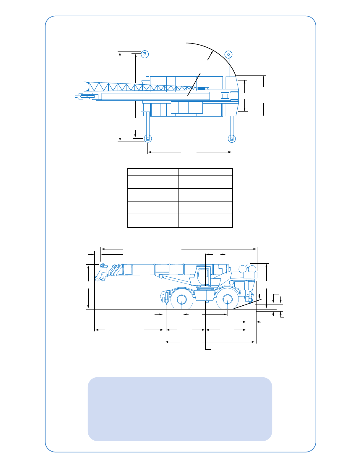
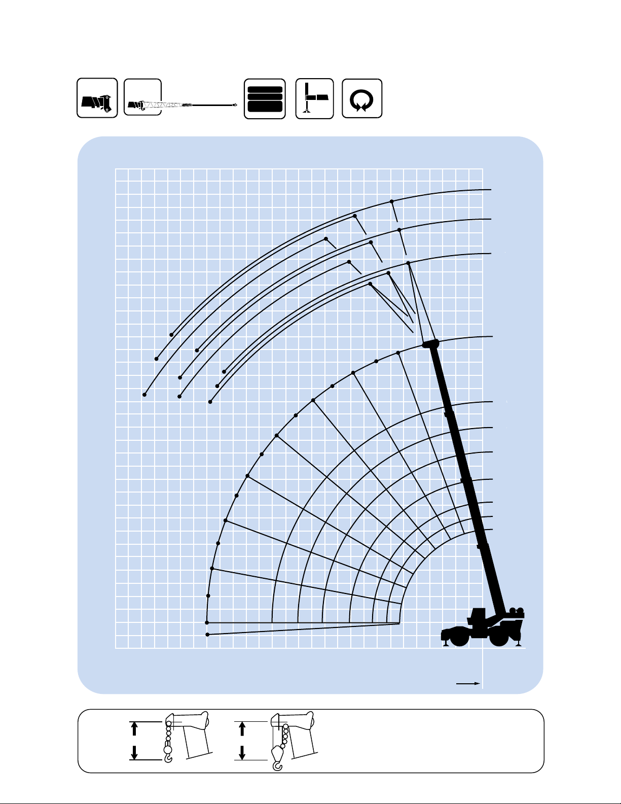
Boom
35 ft.- 110 ft.(10.7 m - 33.5 m) four-section boom
consisting of a base section,two full power sections and
one power pinned section.
Maximum tip height:117 ft. (35.7 m).
*Optional Boom
34 ft.- 84 ft.(10.4 m - 25.6 m) three-section full power
boom.
Maximum tip height:92 ft. (28 m).
Lattice Extension (4 section boom)
32 ft.(9.8 m) lattice swingaway extension.Offsettable at
0°,15° or 30°. Stows alongside base boom section.
Maximum tip height:147 ft. (44.8 m).
*Optional Lattice Extension
(4 section boom)
32 ft.- 56 ft.(9.8 m - 17.1 m) telescoping lattice
swingaway extension offsettable at 0°,15° or 30°.
Stows alongside base boom section.
Maximum tip height: 170 ft.(51.8 m).
Lattice Extension (3 section boom)
32 ft.(9.8 m) fixed lattice swingaway extension.
Stows alongside base boom section.
Maximum tip height:122 ft. (37.2 m).
Boom Nose
Five steel sheaves mounted on heavy duty tapered roller
bearings with removable pin-type rope guards.
*Optional auxiliary boom nose.
Boom Elevation
Two double acting hydraulic cylinders with integral
holding valves provide elevation from -4° to 76°.
Load Moment
& Anti-Two Block System
Standard load moment and anti-two block system with
audio-visual warning and control lever lockout. These
systems provide electronic display of boom angle,
length,radius,tip height, relative load moment,
maximum permissible load and load indication and
warning of impending two-block condition.
Cab
Full vision,all steel fabricated with acoustical lining and
tinted safety glass throughout.Complete driving
controls and engine instrumentation.Dash mounted
control levers for craning functions. Other standard
features include:hinged skylight,sliding left side door
and sliding right side window,electric windshield
wash-wipe,propane heater,circulating air fan,fire
extinguisher,seat belt and two front mounted
worklights.
Swing
Ball bearing swing circle with 360° continuous
rotation.Planetary glide swing with foot applied
multi-disc brake.Spring applied,hydraulically released
parking brake,plunger type one position and 360°
mechanical house lock,operated from cab.
Maximum speed:2.6 RPM.
Counterweight
Integral with turntable mast.
With main hoist only: 13,900 lbs.(6305 kg)
With main & aux.: 12,150 lbs.(5511 kg)
Hydraulic System
Four main pumps with a combined capacity of
146 GPM (553 LPM).
Maximum operating pressure:2500 PSI (172.4 bar).
Four individual valve banks.
Return line type filter with full flow by-pass protection
and service indicator.Replaceable cartridge with micron
filtration rating of 15/30/38.
154 gallon (583 L) reservoir.Remote mounted oil cooler
with thermostatically controlled electric motor driven
fan/air to oil.
System pressure test panel with quick release type
fittings for each circuit.
Hoist Specifications
Main and Auxiliary Hoist
Planetary reduction with automatic spring applied
multi-disc brake.Electronic hoist drum rotation
indicator,hoist drum cable followers and wire rope.
High Low
Maximum Single 9,280 lbs. 18,560 lbs.
Line Pull: (4209 kg) (8419 kg)
Maximum Single 532 FPM 266 FPM
Line Speed: (162 m/min) (81 m/min)
Maximum Permissible 12,920 lbs. 12,920 lbs.
Line Pull: (5860 kg) (5860 kg)
Rope Diameter: 3/4" 3/4"
(19 mm) (19 mm)
Rope Length: 550 ft. 500 ft.
(168 m) (152 m)
Main Auxiliary
Maximum Rope 1,170 ft. 690 ft.
Stowage: (357 m) (210 m)
*Denotes optional equipment