Growcol GHyper 3000 User manual

User Manual
Single Phase Hybrid Inverter
GHYPER-EN-A65-V10-2109


CONTENTS
1. About This Manual ........................................................................1
1.1 Products Covered by This Manual ................................1
1.2 Target Group ..............................................................1
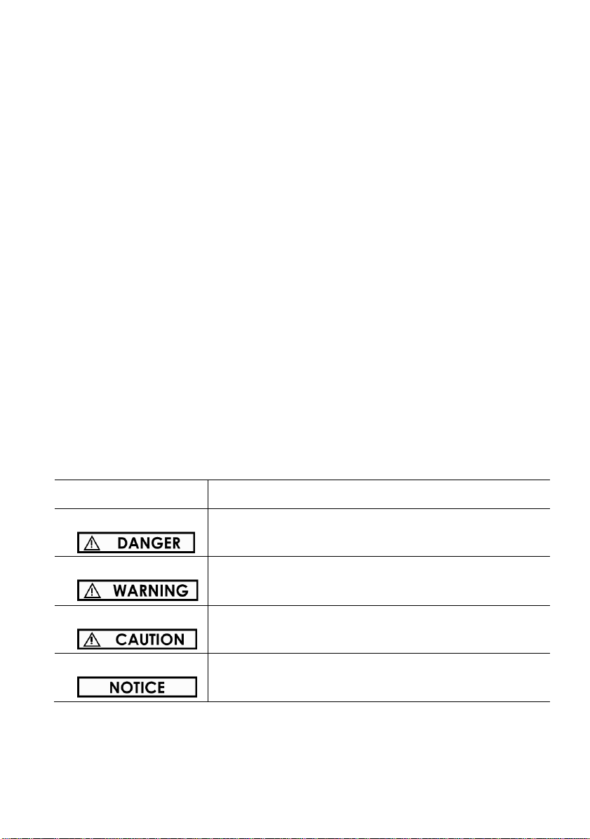
1.3 Symbols ......................................................................1
2. Safety & Warning ..........................................................................2
2.1 Personnel Safety ..........................................................2
2.2 Inverter Protection........................................................2
2.3 Battery Protection.........................................................3
2.4 Electrical Connection ...................................................4
3Product Introduction........................................................................5
3.1 View of the Inverter......................................................5
3.2 System Diagram ..........................................................8
3.3 Working Mode Introduction .........................................9
4 Unpacking and Storage ...................................................................12
4.1 Packing List ..............................................................12
4.2 Storage ....................................................................14
5 Mounting Installation .......................................................................15
5.1 Requirements for Mounting.......................................15
5.2 Mounting Instructions ...............................................17
6Electrical Connection...................................................................21
6.1 Wiring Diagram ........................................................22
6.2 Overview of Connection Area ....................................23
6.3 PV Connection...........................................................24
6.4 Grid Connection .......................................................26
6.5 EPS Connection .........................................................27
6.6 Battery Connection ....................................................28
6.7 Smart Meter Connection ............................................30
6.8 Parallel Connection ...................................................31
6.9 Wi-Fi Stick Connection...............................................32
6.10 DRM Connection .......................................................32
7Operating of the Inverter.............................................................33
7.1 LEDs and Graphical Display .....................................33
7.2 Commission ..............................................................35
7.3 Decommission...........................................................36
7.4 Settings on the APP....................................................37
8Troubleshooting ..........................................................................43

1
1. About This Manual
1.1 Products Covered by This Manual
The manual mainly describes the product information, guidelines for installation,
operation and maintenance. Please read this manual carefully before installations
and operations and keep this manual for future reference.
The manual is valid for GCA Series Low Voltage Solar Hybrid Inverters:
GHyper 3000, GHyper 3680, GHyper 5000
1.2 Target Group
This manual is intended for qualified personnel who are responsible for the
installation and commissioning of the inverter and interact with the inverter. Any
electrical installation and maintenance on this inverter must be performed by
professional electrical personnel who has obtained the license from local
authorities.
1.3 Symbols
Safety instructions will be highlighted with the following symbols. These important
instructions must be followed during installation, operation and maintenance of
the inverter.
Symbol
Description
Indicates a hazard with a high level of risk that, if not
avoided, will result in death or serious injury.
Indicates a hazard with a medium level of risk that, if
not avoided, could result in death or serious injury.
Indicates a hazard with a low level of risk that, if not
avoided, could result in minor or moderate injury.
Indicates a situation that, if not avoided, could result in
equipment or property damage
The information in this manual is subject to change without notice. Please check www.Growcol-
tech.com for more information.

2
2. Safety & Warning
Safety Instructions
The safety instructions in this manual cannot cover all the precautions that should
be followed. Perform operations considering actual onsite conditions. GRWOCOL
shall not be held liable for any damage caused by violation of the safety
instructions in this manual.
2.1 Personnel Safety
• The inverter must be installed, electrically connected, operated and maintained
by specially trained technician;
• The technician must be familiar with the safety regulations of electrical system,
working process of PV power generation system, and standards of local power grid;
• The technician must read through this User Manual carefully before any
operations.
2.2 Inverter Protection
Danger to life from electric shock.
• Do not open the enclosure at any time. Unauthorized opening will void warranty
and in most cases terminate the operating license.
• Do not disconnect the PV connectors or battery connectors when the inverter is
running.
• Wait at least 10 minutes for the internal capacitors to discharge after the battery
is powered off.
• Ensure that there is no voltage or current before installing or disconnecting any
connectors.

3
• All safety instructions, warning labels, and nameplate on the inverter should not
be removed or covered.
Risk of burns from hot surfaces.
• The surface of inverters might exceed 60℃, touching the surface may result in
burns.
• Do not touch hot surfaces before it cools down.
• Only authorized service personnel are allowed to install the inverter or perform
servicing and maintenance
• All powers, both AC and DC, should be disconnected from inverter before
attempting any maintenance or cleaning or working on any circuits connected to
inverter
•As soon as receiving the inverter please check if it is damaged during its
transportation. If yes, please contact your dealer immediately.
•Only qualified personnel can change the country settings.
•Adequate ventilation must be provided for inverter installation location Mount
the inverter in vertical direction, and ensure that no object is put on the heat sink
affecting the cooling.
2.3 Battery Protection
• Batteries deliver electric power, resulting in burns or a fire hazard when they
are short circuited, or wrongly installed.
•Lethal voltages are present at the battery terminals and cables connecting to
the inverter.
• Severe injuries or death may occur if the cables and terminals in the inverter
are touched.

4
• Improper settings or maintenance can permanently damage the battery.
• Incorrect inverter parameters will lead to the premature aging of battery.
2.4 Electrical Connection
• PV strings will produce electrical power when exposed to sunlight and can cause
a lethal voltage and an electric shock.
•Always keep in mind that the inverter is dual power supplied. Electrical
operators must wear proper personal protective equipment: helmet, insulated
footwear, gloves, etc.
• Before touching the DC cables, operator must use a measuring device to ensure
that the cable is voltage-free.
• The operator must follow all warnings on the PV strings and in its manual.
• All electrical connections must be in accordance with local and national
standards.
Only with the permission of the local utility grid company, the inverter can be
connected to the utility grid.

5
3Product Introduction
The hybrid system combining with a hybrid inverter and Low-voltage batteries. The
energy produced by PV system shall be used to optimize self-consumption, excess
power charge battery and the rest power could be exported to the grid. Battery shall
discharge to support loads when PV power is insufficient. If battery power is not
sufficient, the system will take power from grid to support loads.
The hybrid inverter must only be connected with lithium battery approved by
GRWOCOL to prevent personal injury and property damage and to ensure long-
term operation of the product.
3.1 View of the Inverter
View of the Hybrid Inverter

6
Position
Description
1
Inverter
2
LED indicator: Indicates the operating status of the inverter and SOC
of the battery connected.
3
LCD Panel: Displays the current operating data
4
Nameplate Label: Clearly identify the product, including the SN,
technical data, certifications, etc.
5
Middle Control box: Integrated breakers & SPD modules
6
Battery connection area: Red for positive, black for negative
7
PV connection area
8
COM port: Communication port for BMS Cable & Smart Meter Cable
& Parallel Cable
9
EPS output: System will supply emergency power from PV or Battery
to supply some important loads that cannot be powered off
10
GRID connection area: AC input and AC output port(Depend on
different working modes),can supply power by the grid or feed into
the grid (comply with local regulations)
11
EMS port: Wi-Fi Stick communication port
12
PV1 SPD module
13
PV2 SPD module
14
AC SPD module
15
PV1 Breaker
16
PV2 Breaker
17
EPS Breaker
18
Grid Breaker

7
Icons on the Nameplate
Icon
Description
CE Mark: The inverter complies with the requirements of the
applicable CE guidelines
Caution: Risk of Danger
Caution: Risk of Electric Shock!
Caution: Hot Surface.
Refer to the corresponding instructions
5min
Danger to life due to high voltage. Cut off all power and wait
at least 5 minutes before any work is carried out on the
inverter.
RCM mark of conformity
WEEE Mark. Do not dispose of the inverter together with
household waste

8
3.2 SystemDiagram
DC
AC
Communication
Mobile APP Grid
Li-ion
Battery Internet
Billing
Meter
PV Array
Hybrid
Inverter Router Loads
Smart
Meter

9
3.3 Working Mode Introduction
3.3.1 On Grid Self-Use Working Mode (Default)
The on grid self-use operating mode is recommended for when the system is
installed in an area with a stable grid. The purpose is to increase self- consumption
of clean PV energy. When Inverter is set to work in this mode:
During daytime and there is sufficient PV Power
•The PV energy is used to supply local loads as first priority andthen charge the
battery, excess energy will be fed intogrid*1*2.
•When battery is fully charged, PV energy is supplied to the local loads and fed
into grid*1*2.
During nighttime or there is not sufficient PV Power
•The battery is discharged to provide energy to loads. If there is not enough
power from the battery, the unmet power will be supplied by the grid.
•When the battery SOC is below the DischargeEndSOC@Grid value or the
battery is empty, the inverter will stop working and local loads will be
supplied from the grid.
•Thanks to the on-grid operation, the switch from battery power, PV power and
grid power is automatic and seamless.
When grid fails
•When grid fails, the inverter will automatically disconnect from grid and
output power to the EPS port.
•When battery is discharged to the DischargeEndSOC@EPS value, the inverter
will stop working and wait for the grid to recover or until there is sufficient
power from PV panels to charge the battery.
•If grid failure can be a common occurrence in your area, you can adjust the
DischargeEndSOC@Grid higher to ensure there is battery power available.
You can also:
•Set a schedule for the inverter to charge the battery using cheap off-peak grid
power.
•Specify the daily working periods of self-use for inverter.

10
*1: The inverter can be set not to feed power into the grid. But a small amount of
energy will still inevitably be fed into grid due to unpredictable PV energy change
and load fluctuations.
*2: Firmware update may be required to support this function.
For on-grid self-use Working Mode, one can set the discharge end SOC@Grid as
low as the battery allows (10% or 20% for example). Please refer to your local
battery technician for minimum discharging end SOC.
3.3.2 Off Grid / Back-up Working Mode*3
For systems installed in area with a weak grid or even without grid, the inverter
should be working in off grid / back-up Working Mode:
When grid or diesel generator is available
•When the battery is below the DischargeEndSOC@Grid value, it will be
charged firstly from PV and secondly from grid at the max allowable current.
•When the battery is above the DischargeEndSOC@Grid value, it will be
charged by excess PV energy and will discharge if the PV power is not enough
to support the loads.
When grid or diesel generator is not available
•When there is enough energy stored in the battery, the EPS port will export
power to support local loads firstly from PV. If there’s excess PV energy, it will
be used to charge the battery. Otherwise battery will be discharged to feed
the load.
•When the battery SOC is below the DischargeEnd SOC@EPS value, the
inverter will disconnect power to the EPS port. All energy from PV will be used
to charge the battery until the SOC reaches the EPS restart value.
When working in this mode:
•The max power*3 from the EPS port is limited by inverter type, battery type
and battery SOC.
•A larger battery is always recommended for off grid / back up configuration.

11
You should never discharge the battery too deeply to avoid it “Running Flat”.
•When there is an overload or short circuit fault, the inverter will stop working
and an alarm will sound. It will try to restart several times before shutting down
completely. Turn off or unplug load to remove the short circuit fault or overload
as soon as possible.
*2: Firmware update may be required to support this mode.
*3: Please be noted that refrigerators, air conditioners, water pumps and etc., demand
a large start up currents and may trip EPS overload protection. Be sure not to connect
too many of this kind of load to avoid frequent system shutdown and restart.
3.3.4 Declaration for backup loads
Hyper series inverter is able to supply a continuous 5000VA output (max 5500VA
for 10s) on EPS side. Inverter will shut down under full loading with high ambient
temperature if grid is absent.
Accepted loads as below:
• Inductive Load: Max 1.5KVA for single inductive load, max 2.5KVA for total
inductive load power.
• Capacitive load: Total capacitive load (like computer, switch power etc.) power
≤3.0KVA
(Any load with high inrush current at start-up is not supported on EPS circuit)
For off-grid / back-up Working Mode, one should set a higher
DischargeEndSOC@Grid value (above 50% for example). So that there will be
some energy in battery when a grid failure occurs.

12
4 Unpacking and Storage
4.1 Packing List
Make sure the inverter is intact during transportation. Before installation, please
inspect the unit. If there is any visible damage or missing, please contact your local
distributor immediately.
A
B
C
D
E
F
G
H
I
J
K
L
M
N
O
P
Scope of delivery

13
Item
QTY
Description
A
1
Inverter
B
1
Inverter-Bracket
C
1
Battery-Bracket
D
1
Wi-Fi Stick
E
1
Smart Meter
F
3
Terminal Resistor (1kOhm) for Smart Meter
G
5
Expansion bolts for Fixing Inverter-Bracket
H
1
User Manual
I
1
BMS Cable, 0.2m
J
1
Smart Meter Cable, 5m
K
2
Power Cable (Red for positive, black for negative), 0.4m
L
8
Connection terminals for PV and AC cables
M
2
PE terminal for internal enclosure grounding
N
1
PE terminal for external enclosure grounding
O
2
Crystal heads for Parallel connection cable
P
4
Fixed Screws for Fixing Battery-Bracket,M5

14
4.2 Storage
The following storage instructions apply ifthe inverter is not installed immediately.
•Do not unpack the inverter (Store the inverter in the original packing box).
•The storage temperature must be always between -30°C and +70°C, and the
storage relative humidity must be always between 0 and 95 %, non-
condensing.
•In case of stacking storage, the number of stacking layersshould never exceed
the limit marked on the outer side of the packing case.
•Do not position the inverter at a front tilt excessive back tilt or side tilt or
upside down.
•Conduct periodic inspection during storage Replace the packing materials
immediately if any rodent bites are found.
•Ensure that qualified personnel inspect and test the inverter before use if it
has been stored for a long time.

15
5 Mounting Installation
5.1 Requirements for Mounting
•
Make sure there is no electrical connection before installation.
•
In order to avoid electric shock or other injury, make sure that holes will not
be drilled over any electricity or plumbing installations.
•
Always follow the instructions when moving and positioning the inverter.
•
Improper operation may cause injuries or serious wounds.
•
In the case of poor ventilation, the system performance may compromise.
5.1.1 Location Requirements
No direct sunlight
No rain exposure
No snow lay up
Direct sunlight
Rain exposure
Snow lay up
Select an optimal mounting location for safe operation, long service life and
expected performance. Please AVOIDE direct sunlight, rain exposure, snow laying
up during installation and operation. And DO NOT install the inverter in a place
where personnel are likely to come into contact with its enclosure and heat sinks
because these parts are extremely hot during operation.

16
5.1.2 Environment Requirements
The inverter must be installed in a ventilated environment to ensure good heat
dissipation. Make sure the installation site meets the following conditions:
•
Not in areas where accessible to children
•
Not in areas where highly flammable materials are stored.
•
Not in potential explosive areas.
•
Not in the cool air directly.
•
Not near the television antenna or antenna cable.
•
Not higher than altitude of about 2000m above sea level. Above 2000m the
inverter output will be de-rated.
•
Not in environment of precipitation or humidity (>95%).
•
The ambient temperature in the range of -20°C to +60°C, -4°F to+140°F.
•
The slope of the wall should be within ±5°.
•
Do not install the inverter on a wall made of flammable materials or gypsum
boards or similar materials with weak sound insulation.
5.1.3 Angle and Space Requirements
•Never install the inverter horizontally, or with a forward tilt or with a
backward tilt or even with upside down.
•The horizontal installation can result in damage to the inverter.
•Install the inverter upright or at a maximum back tilt of 15 degrees to facilitate
heat dissipation.
This manual suits for next models
2
Table of contents
Other Growcol Inverter manuals
Popular Inverter manuals by other brands

MAER IDROPULITRICI
MAER IDROPULITRICI AVANT 120/11 Instructions for installation and use

KEHUA TECH
KEHUA TECH SPI-B X2 Series user manual

Katana
Katana S610M user manual

BONFIGLIOLI
BONFIGLIOLI Active Cube user manual

Roth
Roth Solarstation ST 20/11 Mounting and operation manual

Tronic
Tronic TSW 150 A1 operating instructions