© Roth 08015 solarstation ST 20/11.mon4Sp.indd
5 |
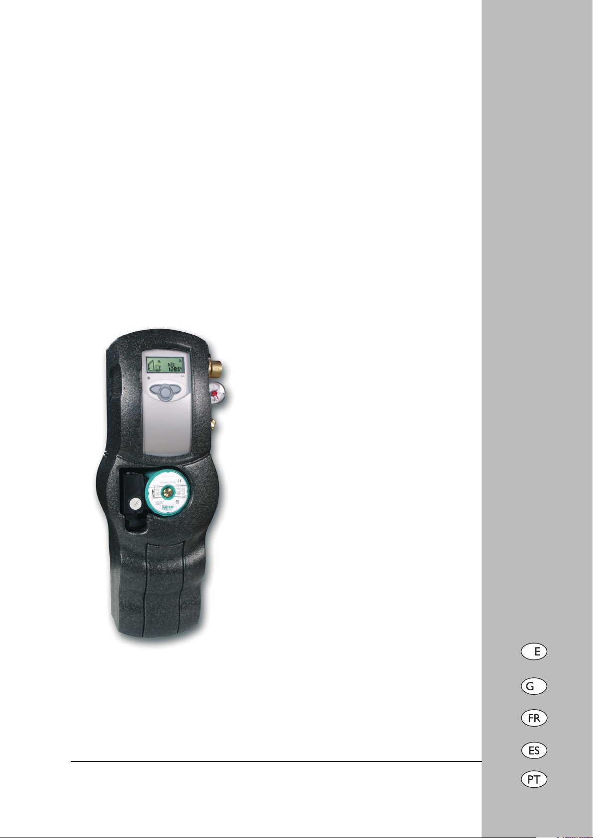
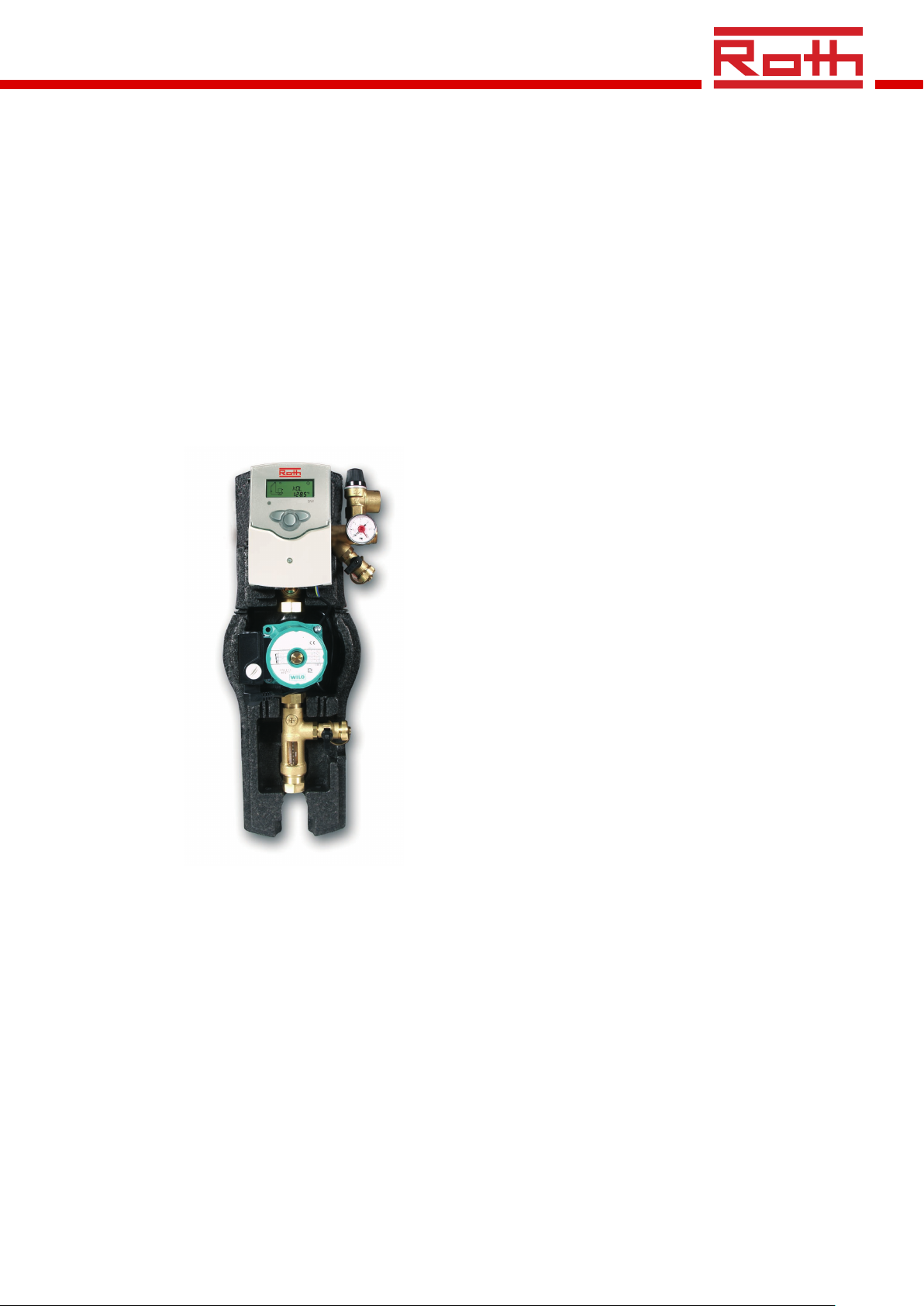
Solarstation ST 20/11
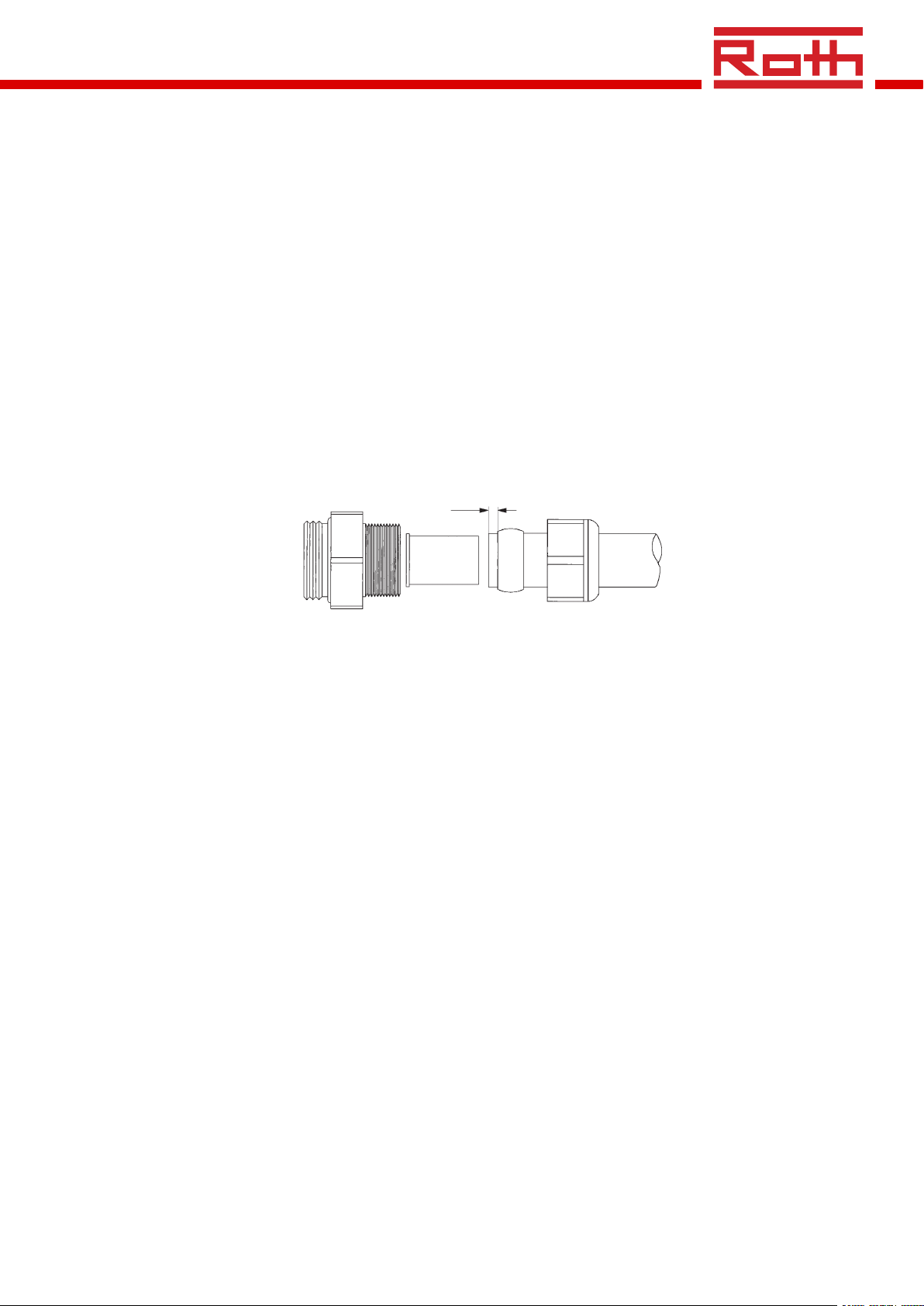
1.2 MontagederRohreindenSchneidring-Verschraubungen
• ZunächstdieÜberwurfmutter(2),danndenMessing-
schneidring (3) auf das Kupferrohr (1) schieben.Damit
eine sichere Krafteinleitung und Abdichtung gewähr-
leistet ist, muss das Rohr mindestens 3mm aus dem
Schneidring heraus stehen.
• DieStützhülse(4)indasKupferrohr(1)hineinschie-
ben.
• DasKupferrohr(1)wirdmitdenaufgestecktenEin-
zelteilen (2; 3; 4) bis zum Anschlag in das Gehäuse der
Schneidring-Verschraubung (5) geschoben.
• DieÜberwurfmutterzunächstvonHandanziehen.
Danach mit einem geeigneten Gabelschlüssel um min-
destens eine ganze Drehung festziehen.
2. Spülen und Befüllen der Anlage
• DenDruckschlauchandenKFE-Hahnunterhalbdes
Manometers anschließen und den KFE-Hahn öffnen.
• Den Spülschlauch an den KFE-Hahn am Flowmeter
anschließen und den Hahn öffnen.
• DerSchlitzderEinstellschraubeamFlowmetermuss
in waagerechter Stellung stehen.Der integrierte Kugel-
hahn ist somit geschlossen (siehe Bedienungsanleitung
für Flowmeter). Die Schwerkraftbremse über der
Pumpe öffnen; den Kugelhahn dazu mit einem 14-ner
Maul- bzw.Gabelschlüssel in 45°-Stellung (halb geöffnet,
halb geschlossen) bringen.
• FürdieAnlageausreichendSolarüssigkeitindenBehäl-
ter einer Spül- und Befüllstation (nicht im Lieferumfang
enthalten) geben und die Solaranlage befüllen.
• MittelsderSpül-undBefüllstationdenSolarkreismind.
15 min.spülen.Um die komplette Luft aus derAnlage zu
bekommen,ist es notwendig,zwischendurch kurzzeitig
die Einstellschraube am Flowmeter zu öffnen (Schlitz
senkrecht).
• Die komplette Solaranlage niemals nur mitWasser
spülen oder abdrücken. Da ein vollständiges Entleeren
der Anlage meist nicht möglich ist, besteht die Gefahr
von Frostschäden.
• Den Spül-KFE-Hahn (Ablaufhahn) bei laufender Be-
füllpumpe schließen und den Anlagendruck auf ca. 5
bar erhöhen. Der Anlagendruck kann am Manometer
abgelesen werden.
Bitte beachten:
Damit die Dehnungs-Spannungen der Rohre aufgefangen
werden, sind entsprechende Armaturen (Dehnungsmuffen)
oder Rohr-Etagen (bestehend aus mindestens zwei 90°Bö-
gen) erforderlich.
Für Rohr-Etagen muss der Abstand zwischen den Bögen
größer sein als der doppelte Rohr-Durchmesser in cm
[Beispiel: Rohrdurchmesser = 18 mm Abstand der Bögen
mehr als 36 cm].
• DenBefüllhahnschließenunddiePumpederSpül-und
Befüllstation abschalten, die Einstellschraube am Flow-
meter öffnen (Schlitz senkrecht).
• DieAnlageoberhalbderKollektorenentlüften,bisdie
Anlagenüssigkeit blasenfrei austritt. Den Prüfdruck
wieder auf ca. 6 bar erhöhen und die Anlage auf Dich-
tigkeit überprüfen. Bei deutlichem Druckabfall am
Manometer muss von einer undichten Stelle im System
ausgegangen werden.
• DenBetriebsdruckgemäßAnlagenherstellereinstellen
(ggf. auf ca. 1,8 bis 2,3 bar bei Kollektorhöhe über dem
Manometer ca. 5 bis 10 m-dabei den Vordruck des
Ausdehnungsgefäßes beachten).
• DieUmwälzpumpeaufhöchsterDrehzahlstufeinBe-
trieb nehmen (s. Betriebsanleitung zu der Pumpe) und
mindestens 15 min. zirkulieren lassen.
• AnschließenddieUmwälzpumpeaufdiegewünschte
Drehzahlstufe einstellen.
• DenVolumenstromamFlowmetergemäßderAngabe
des Kollektorherstellers einstellen.
• Die Schläuche der Befüllstation abnehmen und die
Verschlüsse auf die Spül- und Befüllhähne schrauben.
• DieAnlagenochmalsaufDichtigkeitüberprüfen.Den
Kugelhahn über der Pumpe vollständig öffnen.
• DievordereIsolierschalederSolarstationanbringen.
5
43
2
1
> 3 mm