GRP Synthesizer R24 User manual

1
Grp Synthesizer
R24 Step Sequencer
Owner’s Manual
Version 1.2
www.grpsynthesizer.it
0
1
2
3
456
7
8
9
10
ROW GATE
CV OUT CONTROL IN
FIRST GATE
END GATE ORDER
STEP REPEAT
ROW REPEAT
ADV DIV
0/+8V
STEP GATE 0/+5V
CV OUT
C
TRNP C
ROW GATE
CV OUT
FIRST GATE
END GATE ORDER
STEP REPEAT
ROW REPEAT
ADV DIV
0/+8V
STEP GATE 0/+5V
CONTROL IN
GATE 2
GATE 1
B
CV OUT B
TRNP B
ROW GATE
GATE OUT CV OUT CONTROL IN
FIRST GATE
END GATE ORDER
STEP REPEAT
ROW REPEAT
ADV DIV
0/+8V
STEP GATE 0/+5V
ON
PORTAMENTO
QNTRNG X2 S&H
X4
X8
0
1
2
3
456
7
8
9
10
ON
PORTAMENTO
QNTRNG X2 S&H
X4
X8
23
FNC 1
ENDSTPGATE 2
OFF
SKIP
FNC 2
b #
OFF NORM
GATE 1
24
FNC 1
ENDSTPGATE 2
OFF
SKIP
FNC 2
b #
OFF NORM
GATE 1
22
FNC 1
ENDSTPGATE 2
OFF
SKIP
FNC 2
b #
OFF NORM
GATE 1
21
FNC 1
ENDSTPGATE 2
OFF
SKIP
FNC 2
b #
OFF NORM
GATE 1
20
FNC 1
ENDSTPGATE 2
OFF
SKIP
FNC 2
b #
OFF NORM
GATE 1
19
FNC 1
END STPGATE 2
OFF
SKIP
FNC 2
b #
OFF NORM
GATE 1
18
FNC 1
ENDSTPGATE 2
OFF
SKIP
FNC 2
b #
OFF NORM
GATE 1
17
FNC 1
ENDSTPGATE 2
OFF
SKIP
FNC 2
b #
OFF NORM
GATE 1
15
FNC 1
ENDSTPGATE 2
OFF
SKIP
FNC 2
b #
OFF NORM
GATE 1
16
FNC 1
ENDSTPGATE 2
OFF
SKIP
FNC 2
b #
OFF NORM
GATE 1
14
FNC 1
ENDSTPGATE 2
OFF
SKIP
FNC 2
b #
OFF NORM
GATE 1
13
FNC 1
ENDSTPGATE 2
OFF
SKIP
FNC 2
b #
OFF NORM
GATE 1
12
FNC 1
ENDSTPGATE 2
OFF
SKIP
FNC 2
b #
OFF NORM
GATE 1
11
FNC 1
ENDSTPGATE 2
OFF
SKIP
FNC 2
b #
OFF NORM
GATE 1
10
FNC 1
ENDSTPGATE 2
OFF
SKIP
FNC 2
b #
OFF NORM
GATE 1
09
FNC 1
ENDSTPGATE 2
OFF
SKIP
FNC 2
b #
OFF NORM
GATE 1
07
FNC 1
ENDSTPGATE 2
OFF
SKIP
FNC 2
b #
OFF NORM
GATE 1
08
FNC 1
ENDSTPGATE 2
OFF
SKIP
FNC 2
b #
OFF NORM
GATE 1
06
FNC 1
ENDSTPGATE 2
OFF
SKIP
FNC 2
b #
OFF NORM
GATE 1
05
FNC 1
ENDSTPGATE 2
OFF
SKIP
FNC 2
b #
OFF NORM
GATE 1
04
FNC 1
ENDSTPGATE 2
OFF
SKIP
FNC 2
b #
OFF NORM
GATE 1
03
FNC 1
ENDSTPGATE 2
OFF
SKIP
FNC 2
b #
OFF NORM
GATE 1
02
FNC 1
ENDSTPGATE 2
OFF
SKIP
FNC 2
b #
OFF NORM
GATE 1
01
FNC 1
ENDSTPGATE 2
OFF
SKIP
FNC 2
b #
OFF NORM
GATE 1 GATE OUT
RUN/STOP
C
REMOTE CLOCK
LOOP ON/OFF
GLIDE ON/OFF
ADV MODE
SEQ MODE
0/+5V
SEQ CLK MOD
CONTROL IN
0/+5V
MOM SWITCH - 0/+5V
CLOCKIN
CLOCKOUTSEQ PW MOD
GLOBAL SETTINGS
GATE
PULSE WIDTH
PROGR PWMOD
MAIN
A+B+C
A+B,C
SEQ MODE
A,B,C
STEP ADV
GATE ON
ON
GLOBAL LOOP
RUN/STOP
PLAY
SHIFT
RESET
A
B
0
1
2
3
456
7
8
9
10
ON
PORTAMENTO
QNTRNG X2 S&H
X4
X8
R24
Grp Synthesizer®
B
GATE 2 C
GATE 1C
GATE OUT
0
1
2
3
456
7
8
9
10
STP RPTORDER ROWRPT
X2
X3
X4
ADV DIV
/2
/3
/4
/8
/16
1.2
1.2.1
1.1.2.1
1.3.5
1.2.3.2.1
D
X2
X3
X4
8
ON
STP RPTORDER ROWRPT
X2
X3
X4
ADV DIV
/2
/3
/4
/8
/16
1.2
1.2.1
1.2.3.2.1
1.3.5
D
X2
X3
X4
8
ON
STP RPTORDER ROWRPT
X2
X3
X4
ADV DIV
/2
/3
/4
/8
/16
1.2
1.2.1
1.3.5
D
X2
X3
X4
8
ON
CV OUT +B+CA
A
GATE2 +B+C
A
GATE1 +B+C A
TRNP +B+C
0
1
2
3
456
7
8
9
10
CLK SEL
INT
EXT
MIDI
CLKMOD
FREQUENCY
CLOCK
ROW C
ROW A
ROW B
ALT
FW
FW/BW
BW
RND
PNDL
ADVANCE MODE
D
D
D
ASSIGN
RESET
RESET
RESET
RESET
MOM SWITCH
1.1.2.1
1.2.3.2.1
1.1.2.1
STORE

Grp R24 Step Sequencer –Owner’s Manual
2
This page is intentionally blank

Grp R24 Step Sequencer –Owner’s Manual
3
CONTENTS
Foreword
Warnings and Specifications
R24: Main Functions
STEP Parameters
LED
Pot Value
Switch GATE 1 / OFF / GATE 2
Switch OFF / FNC 1 / FNC 2
Switch NORM / SKIP / END STEP
ROW Parameters
Management Parameters (Rows A, B & C)
Pot PORTAMENTO
Switch RANGE X2 / X4 / X8
Switch S&H ON
Switch QNT ON
Interpretation Parameters (Fila A, B & C))
LED ON
Switch ORDER
Switch STP RPT (STEP REPEAT)
Switch ROW RPT (ROW REPEAT)
Switch ADV DIV (ADVANCE DIVISION)
Mode RESET
Mode ON (File B & C)
ROW Connections
Connections GATE OUT (Row A)
STEP GATE
FIRST GATE
END GATE
ROW GATE
GATE 1 A+B+C
GATE 2 A+B+C
Connections CV OUT (Row A)
Port CV OUT A+B+C
Connections CONTROL IN (Row A)
Port ORDER
Port STEP REPEAT
Port ROW REPEAT
Port CLOCK DIV
Port TRNP A+B+C
Connections GATE OUT (Row B)
STEP GATE
FIRST GATE
END GATE
ROW GATE
GATE 1 B
GATE 2 B
Connections CV OUT (Row B)
Port CV OUT B
Connections CONTROL IN (Row B)

Grp R24 Step Sequencer –Owner’s Manual
4
Port ORDER
Port STEP REPEAT
Port ROW REPEAT
Port CLOCK DIV
Port TRNP B
Connections GATE OUT (Row C)
STEP GATE
FIRST GATE
END GATE
ROW GATE
GATE 1 B
GATE 2 B
Connections CV OUT (Row C)
Port CV OUT C
Connections CONTROL IN (Row C)
Port ORDER
Port STEP REPEAT
Port ROW REPEAT
Port CLOCK DIV
Port TRNP C
SEQUENCE Parameters
Section Assign
Button ROW A
Button ROW B
Button ROW B
Section Clock
Control FREQUENCY
Selector CLOCK SEL
Switch CLK MOD
Section ADVANCE MODE
Button FW
Button BW
Button FW&BW
Button PNDL
Button ALT
Button RND
Section MAIN
Selector SEQ MODE
Switch GLOBAL LOOP
Switch SHIFT
Button STEP ADV
Button RUN/STOP
Button RESET
Section PULSE WIDTH
Control Gate
Switch PW MOD
SEQUENCE Connections
Section REMOTE
Port RUN/STOP
Port LOO ON/OFF
Port RESET
Port GLIDE ON/OFF
Section CLOCK
Port CLOCK OUT
Port CLOCK IN
Section CONTROL IN

Grp R24 Step Sequencer –Owner’s Manual
5
Port ADV Mode
Port SEQ CLK MOD
Port SEQ MODE
Port SEQ PW MODE
Section Global Settings
From BPM screen to Parameters Display Menu
Navigation
Available Menu
Menu MIDI
Parameter Channel Transmit
Parameter Channel Receive
Parameter Velocity
Parameter Low Note
Parameter Transpose
Menu TIME DIVISION
Parameter Time Division
Menu FUNCTION
Parameter Function
Menu CLOCK
Parameter CLOCK
Menu MEMORY
Parameter Read
Parameter Write
Parameter Panel
Menu MODE
Parameter MODE
Menu ORDER
Parameter Order Read
Parameter Order Write
Menu CLOCK DIVIDER
Parameter Clock Divider
Menu FACTORY

Grp R24 Step Sequencer –Owner’s Manual
6
FOREWORD
Thank you for purchasing the Grp Synthesizer R24 Step Sequencer: this machine will rewards you
with years of sonic satisfactions and, to ensure your instrument will functions properly, please read
this manual.
SOME WORDS OF WISDOM
Read the following safely tips carefully! You should always observe some basic precautions when
dealing with electronic equipment, for you safety and for safety of your own equipment.
OPERATING CONDITIONS
Never use the synthesizer under potentially damp/wet conditions such bathrooms,
swimming pools, etc.
Do not use the instrument in extremely dusty and dirty environments.
Do not place the instrument near heat sources like radiators.
Do not expose the instrument to direct sunlight; the wooden cabinet is varnished with a
traditional and trusted procedure, but ultraviolet rays from sunlight can quickly fade the
original wooden colour.
Do not expose the device to extreme vibrations.
Save the original crate and boxing for future shipping of the instrument.
POWER SUPPLY
Your Grp R4 Step Sequencer is already set for the correct AC powering for your area. You
can read it on the label in the rear panel.
Unplug the device when you are not using it for longer periods.
Never touch the plug with wet hands.
When unplugging the instrument, always grab and pull the plug, never the cable.
OPERATION
Although you are a rockstar, NEVER place cans of beer, coke, water (?) or other potentially
spilling liquids on or near the instrument.
The Grp R24 Sequencer is an heavy unit: place it on a suitable solid surface or table.
MAINTENANCE
Do not open the instrument; do not unscrew the front/rear panels. Inside the instrument,
there aren’t user’s serviciable parts.
PROPER USE
This synthesizer is designed exclusively to produce audio rate frequency signals for musical
purpose. Any other use is prohibited and voids the warranty extended by Grp Synthesizer.
Grp Synthesizer is non liable for damages due to incorrect use.
TECHNICAL
Powering:
+15V = 160 mA
-15V = 43 mA
+5V = 110 mA
WARNING
Step Sequencer R24 is mechanically unsuitable housing in lower row of 5U slanted cabinet.

Grp R24 Step Sequencer –Owner’s Manual
7
R24: MAIN FUNCTIONS
Mainly, R24 can be considered the union of two separate units:
A cabinet with dedicated power, ready to house and powering third party modules in 5U
format, in respect of electric and mechanical formats from COTK, DotCom, MoonModular,
etc. The cabinet is the same in use with Grp A2 Synthesizer; this is the reason for the double
writings on MIDI Ports on back panel.
The Step Sequencer, playable in stand alone –with its cabinet –or mountable in a 5U
cabinet (DotCom, Moon Modular, etc), in full respects of mechanical and electrical
standars. See in the end of this manual for power consumption on +15V, -15V and +5V. With
the enclosed rack ears, the Sequencer can be easily mounted in a standard 19” rack.
The structure of Step Sequencer is 8x3, organized in three Rows of eight Steps each one, but you
can choose several SEQUENCER MODE for work with three separate parallel sequences (max 8
Steps each one), one Sequence max 16 Steps plus one Sequence Max 8 Steps in parallel, or with
only one big Sequence of max 24 Steps.
Every Row A, B and C has a several parameters per Row and per Step; so, the R24 Step Sequencer
architecture is organized in an easy structure:
Step Parameters
Row Parameters
oRow Connections
Sequence Parameters
Global Parameters
oSequence and Global Connections.
R24 can do and offers:
Memorize 64 sequences, each one including all the setting values on front panel or
programmed into Display and Menus.
Organize 24 Steps in three parallel Sequences A,B and C; two parallel Sequences A+B, C;
just one Sequence A+B+C; in all three cases, user can define freely the lenght of
Sequences.
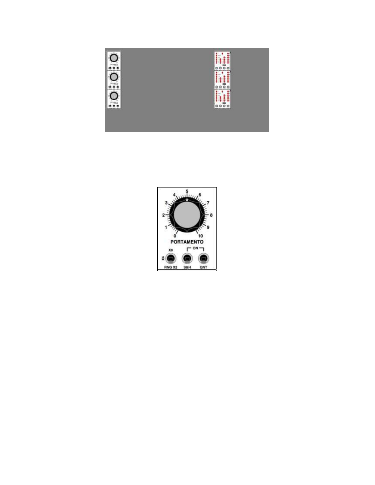
Every Step can be enriched with two additional parameters/programmable functions
(ratchet bouncing, Portamento On/Off, etc).
Every Sequence can interpret Step Order with independent rules of density, advance
mode, iteration and repetigion, available on front panel and user’s customizable from
Display.
Every Step can organize Gate emission on two separate Gate Bus Out, freely assignable, for
quick creation of rhythms and structures.
A huge array of analog connections for control and trasmission allows interaction between
multiple sequencers, external CV control on several R24 parameters and work with several
Clock Sources.
Work in 1V/Oct format standard; Hz/Oct format for CV and Gate will be available in a next
soft revision.
Semitone quantization in 1/12V standard; in a next soft revision, will be covered V/Hz
standard.

Grp R24 Step Sequencer –Owner’s Manual
8
STEP PARAMETERS
Following descriptions are valid for every Step on Rows A, B & C. Each Step on every Row has:
LED
LED turns ON when Step is played; still, the color is red when Step sends its Gate on Gate Bus
1, color is blue when Gate goes on Gate Bus 2. (See below, Switch Gate1/Off/Gate2).
Pot VALUE
CV Value on each Step is adjustable in 2, 4 or 8 Volts range (See below, ROW Parameter);
Step is tunable with the pot Value.
Switch GATE 1 / OFF / GATE 2
Choose if 0/+5V tension of the Step goes to:
lower position, on bus GATE 1 on the corresponding out port GATE 1 (with all the
routings available over the three Rows);
central position, in OFF, there’s no Gate transmission for selected Step;
upper position, on bus GATE 2 on the corresponding out port Gate 2 (with all the
routings available over the three Rows).
By Default, this switch is in lower position, routing to Gate 1.
Switch OFF / FNC 1 / FNC 2
Enables one of two User’s selectable Functions per Step (Functions are assigned via Display
on a per Row basis, with independent enable Step by Step). By Default, the three position
switch has assigned:
lower position, OFF; no function assigned to Step;
central position, FNC 1; Function 1 recalls Ratched with two bounces per Step;
upper position, FNC 2; Function 2 recalls Ratchet with three bounces per Step.

Grp R24 Step Sequencer –Owner’s Manual
9
NOTE: a Step with two or three bounces/Ratchet mantains the same length of other Steps; bounces
density is created with brand new Gate On/Off articulations.
NOTE: to reach full menu of available functions assignable to both positions of the switch, see
below the DISPLAY Parameter Section.
Switch NORM / SKIP / END STEP
Defines how to interpret the Step; is it possibile choose between:
lower position, NORM, Step is read in a normal way and Sequence goes to the
following Step;
central position, SKIP; Step is skipped, Sequence duration is shortened. Unlike
behaviors GATE 1/Off/GATE 2 seen before, a 4 Step Sequence, with one Step in SKIP
mode, lasts only three Steps; a four note-Sequence with one Step in GATE OFF, lasts
regularly four Steps, but plays three Steps with a note and one Step with a pause.
upper position, END STEP; Step is regularly read and played as Sequence’s terminal.
To obtain a four Step-Sequence, fourth Step should be set on END STEP.
WARNING: The Default condition, for the “normale” behavior of Sequencer’s ROW correspond at
lower positioning on all three switches available on every Step; each switch set in middle or upper
position will differs from standard “normal” Default.

Grp R24 Step Sequencer –Owner’s Manual
10
ROW PARAMETERS
Each Row has management parameters (on left-hand column) and interpration (on right-hand
column) influencing all active Steps. Many parameters are in common for all three Rows A, B and
C; on some cases, parameters are available only on certain Rows; the following descriptions
highlights on each case parameters available on selected Sequencer’s Rows.
Management Parameters (Rows A, B & C)
Define modes used for evaluate Steps values on every Row.
Pot PORTAMENTO
Sets Portamento speed applied on CV programmed in every Step.
NOTE: If neither FNC 1 nor FNC 2 has been assigned to Portamento On/off, the behavior is applied
globally on every active Step in a Row (or in a Sequence, if seq lenght and SEQ MODE differs from
standard 8-step length). For individual Step setting of Portamento On/Off, see below at Display
Parameter Section.
NOTE: Either if sequence is longest than one Row(SEQ MODE on A+B,C or A+B+C), the Portamento
On/Off parameter possibily assigned to FNC 1 or FNC 2 is active only on its Row. This can drive to a
peculiar condition: a 16-Step Sequence can have Steps 1-8 with individual On/Off Portamento
setting and Steps 9-16 not, for a different function assigned by the User. It’s a fairly powerful
capability, but can drive to some confusion. For a list of available functions, see belov the Display
Parameter Section.
Switch RANGE X2 / X4 / X8
Sets range for Step CV; you can choose a range of 2, 4 or 8 Volts corresponding to switch
positions X2, X4, X8. In all three cases, zero value corresponds to full counter-clockwise
position of STEP VALUE control:

Grp R24 Step Sequencer –Owner’s Manual
11
lower position, RANGE X2; Step range covers 2 Volts, e.g. 2 octaves;
central position, RANGE X4; Step range covers 4 Volts, e.g. 4 octaves;
upper position, RANGE X8; Step range covers 8 Volts, e.g. 8 octaves.
Switch S&H ON
Turns on the Sample and Hold circuit on Row CV Out at corresponding analog port CV OUT
(see below, Connections Section). S&H sample new values on each Gate On programmed
for every Step with Switch GATE 1 / OFF / GATE 2. So, it is possible to prolong the
programmed value for one Step to next Step (assuming that next Step is in Gate Off
condition).
with switch ON, same value from first Step is prolonged e.g. latched over the second
Step in Gate Off.
With switch OFF, value programmed in second Step will reach anyway its
destination, though in absence of Gate articulation. This condition will lead to an
unpleasant yodeling with oscillators, especially if amplitude envelope has a long
release time.
Switch QNT ON
Turns on and off chromatic quantization on Row CV Out; quantization can be handy for
tuning a Sequence with 4 or 8 Volts range (e.g. four or eight octaves span over pot STEP
VALUE).
NOTE: In the now available Revions 1.0 for Step Sequencer R23, there is only one chromatic
quantization mask, with octave subdivided in 1/12th of Volt; in a next software upgrade, there’ll be
a quantization mask especially conceived for work with Hz/Oct standard.
Interperation Parameters (Row A)
They sets the interpretation modes of ordering, reading and executing values programmed on
each actie Step of the Row. This section can be considered like a control unit for Row piloting.
NOTE: Each Row has its own independent section, but “which section” is active is displayed by the
ON LED and it’s decided with the selected SEQ MODE in R24 Sequencer. So, if R24 acts like a single
Sequencer with 24 Steps (Mode A+B+C), there’ll be just one control unit turned on for Row A; when
R23 acts like a dual Sequencer 16+8 Steps (Mode A+B, C), there’ll be two control units turned on for
Rows A (acting over Rows A&B) and Row C; still, when R24 works like a three-Sequencers in paralle
(Mode A,B,C), there’ll be all three control units turned on and active on the respective Rows.
NOTE: Repeatedly pressing on switches will cyclic “forward” advance in the selection of
parameters from lowest to highest option; at the end, selection will start back again from the lowest
position. If using combination SHIFT+Parameter switch, selection will proceed with inverted
advance, e.g. from highest to lowest available position. SHIFT button is in MAIN Control Section.

Grp R24 Step Sequencer –Owner’s Manual
12
LED ON
Turns On if control unit is active and functioning over corresponding Row(s).
Switch ORDER
Defines the iteration rule used for read the active Steps. An eight-Step Sequence
1.2.3.4.5.6.7.8 will be read in the following modes:
1.2.; 1.2. 2.3. 3.4. 4.5. 5.6. 6.7. 7.8. etc; duplets advancing;
1.2.1.; 1.2.1. 2.3.2. 3.4.3. 4.5.4. 5.6.5. 6.7.6. etc; triplets advancing;
1.3.5.; 1.3.5., 2.4.6., 3.5.7, 4.6.8., etc;
1.1.2.1; 1.1.2.1., 2.2.3.2., 3.3.4.3., 4.4.5.4., 5.5.6.5., 6.6.7.6., etc;
1.2.3.2; 1.2.3.2., 2.3.4.3., 3.4.5.4., 4.5.6.5., 5.6.7.6, etc;
D., this position (D for Display) recalls the User’s programmable iteration function; this
is freely Row-recallable with Parameter Display. See below.
Switch STP RPT (STEP REPEAT)
Sets how many times Steps is repeated before passing to next Step; when LED column is
completely turned off, there’s no repetition (each active Step is read only one time); you
can choose between 2, 3 or 4 repetitions, corresponding to LED on X2, X3, X4.
Step ROW RPT (ROW REPEAT)
Usually, every Step Sequencer not set on One Shot, repeats its Sequence ad infinitum; R24
offers fairly complex repetition schemes useful for reorganize in real time playing of two or
three Sequences simultaneously (SEQ MODE on A,B,C and A+B,C).
ROW RPT parameter allows you to choose if Row is repeated ad infinitum (option ∞) or a
finite number of times (options X4, X3, X2, corresponding to four, three and two repetitions
for Row). On completion of the number of repetition specified, Row playback stops.
NOTE: This parameter is active only if mode GLOBAL LOOP (in the MAIN Section of R24 Sequencer) is
in OFF position.
Switch ADV DIV (ADVANCE DIVISION)
Each Row can advance its Steps with a dividing factor applied on selected Clock Source
(in CLOCK Section, with command CLK SEL). So, one Row can advance at speed /2, /3, /4,
/6, /8, /16, D in respect of original density of clock train of pulses. Last position, marked D
refers at freely user’s adjusted value for each Row. Refer below to Parameter Display
Section.
NOTE: Step Sequencer R24 provides an additional global level of Clock Divider Menu Display. See
below on Parameter Display Section.
Mode RESET
By simultaneously pressing buttons STORE and ROW REPT on selected Row, you’ll force restar
for the Row from the first active Step.

Grp R24 Step Sequencer –Owner’s Manual
13
ROW CONNECTIONS
Each Row has dedicated connections for transmission of analog controls (CV and Gate) and for
remote control –from external analog equipment –on most important parameters.
Connections GATE OUT (Row A)
This block contains four connections.
STEP GATE FIRST GATE
This port emits a Gate 0/+5V every time the first active Step is played in the Sequence.
Useful for start several generators in parallel or for firing other external events.
STEP GATE END GATE
This ports emits a Gate 0/+5V every time the last active Step is played in the Sequence (the
Step on which has been selected END STEP behavior with the upper position of switch NORM
/ SKIP / END STEP). Useful for start several Sequencers connected in series.
ROW GATE GATE1 A+B+C
This port emits a train of Gate pulses corresponding at each active Steps in Row A (SEQ
MODE in position A,B,C), in Rows A andB (SEQ MODE in position A+B, C), in Rows A, B and C
(SEQ MODE in position A+B+C). Useful for start envelope generators or several external
events.
At this port, obviously, will appears only Gate tensions relative to Steps assigned on Gate 1
position with switch Gate 1 / Off / Gate 2.
ROW GATE GATE2 A+B+C
This port emits a train of Gate pulses corresponding at each active Steps in Row A (SEQ
MODE in position A,B,C), in Rows A andB (SEQ MODE in position A+B, C), in Rows A, B and C
(SEQ MODE in position A+B+C). Useful for start envelope generators or several external
events.

Grp R24 Step Sequencer –Owner’s Manual
14
At this port, obviously, will appears only Gate tensions relative to Steps assigned on Gate 2
position with switch Gate 1 / Off / Gate 2.
NOTE: The internal normalizaton allows changing SEQ MODE, reconfiguring behavior of R24 Step
Sequencer, while mantaining physical patch cord connections for Gate Out, thus avoiding
repatching every time you’ll change mode/length/configuration for the whole Sequencer.
Connections CV OUT (Row A)
This block contains just one connection.
Connection CV OUT A+B+C
This port emits CV Out (0/+8V in three selectable ranges with Row switch RANGE X2/X4/X8)
corresponding at the values programmed on each active or inactive Step (see NOTE
below) for Row and Sequence. Will be emitted only CV for Steps 1-8 if Step Sequencer R24 is
in SEQ MODE A,B,C; will be emitted CV for Steps 1-16 if R24 is in SEQ MODE A+B,C; will be
emitted CV for Steps 1-24 if R24 is in SEQ MODE A+B+C. In this way, as stated before, user
can avoid repatching cables when changin configuration of SEQ MODE.
NOTE: Step are always emitting their CVs, either by activation of GATE1/GATE2; the only way to
avoid CV out from a Step consists in selecting SKIP STEP condition for the undesider Step value (this
will shorten the sequence).
But, if you desperately want a Step not assigned on a Gate bus 1or 2 doesn’t transmit its value over
CV Out, or if you want to prolong arbitrarily (for multiples of Step duration) the duration of a CV
smearing over more than one Step, you can use the S&H ON mode (using the dedicated Row
switch), for latching the value. In this way, CV Out will be sampled and mantained in memory
(hold) until the next Gate enabled. Only Steps assigned on GATE1/GATE2 will be allowed to transmit
Out their CV values. Other CV values from Steps unassigned will be ignored.
Connections CONTROL IN (Row A)
This block of five ports permits remote control of five parameters thru external CV comprised
between 0 and +5V during Sequence playback. Still, is available a Transpose Input for real-time
transposing of Step values.
Port ORDER
An external CV, comprised between 0 and +5V, sets ORDER parameter, for remote choice
of advance type for all the Steps enabled. Choice with external CV turns on the
corresponding LED in the ORDER LED column.
Port STEP REPEAT
An external CV, comprised between 0 and +5V, sets STEP REPEAT parameter, for remote
choice of number of repetition for all the Steps enabled. Choice with external CV turns on
the corresponding LED in the STEP RPT LED column.
Port ROW REPEAT
An external CV, comprised between 0 and +5V, sets ROW REPEAT parameter, for remote
choice of number of repetition for the Row. Choice with external CV turns on the
corresponding LED in the ROW RPT LED column.
Port CLOCK DIV
On each Row, Step advance rate is connected at “dimension iso rhythmic” assigned to
enabled Steps; starting from an arbitrary Clock density (see below on Parameter Display for
the dividing factors applyable on Clock signals generated and received by Step Sequencer
R24), user can choose if Steps will advance with a rhythmic division independent on each
Row. Port CLOCK DIV is enabled to receive an external CV comprised between 0 and +5V
for choosing the selected rhythmic division. Choice with external CV turns on the
corresponding LED in the CLOCK DIV LED column.

Grp R24 Step Sequencer –Owner’s Manual
15
Port TRNP A+B+C
Adds an analog CV comprised between 0 and +5V to the programmed Step values for
real-time transpose of the Sequence.
Signal received at port TRNP A+B+C is active on Steps 1-8 in SEQ MODE A,B,C; is active on
Steps 1-16 in SEQ MODE A+B,C; is active on Steps 1-24 in SEQ MODE A+B+C avoiding
repatching every time SEQ MODE will change.
Connections GATE OUT (Row B)
This block contains for ports.
STEP GATE FIRST GATE
This port emits a Gate 0/+5V every time the first active Step is played in the Sequence.
Useful for start several generators in parallel or for firing other external events.
STEP GATE END GATE
This ports emits a Gate 0/+5V every time the last active Step is played in the Sequence (the
Step on which has been selected END STEP behavior with the upper position of switch NORM
/ SKIP / END STEP). Useful for start several Sequencers connected in series.
Port ROW GATE GATE1 Out B
This port emits a train of Gate pulses corresponding at each active Steps in Row B (SEQ
MODE in position A,B,C. Useful for start envelope generators or several external events.
At this port, obviously, will appears only Gate tensions relative to Steps assigned on Gate 1
position with switch Gate 1 / Off / Gate 2.
Port ROW GATE GATE2 Out B
This port emits a train of Gate pulses corresponding at each active Steps in Row B (SEQ
MODE in position A,B,C. Useful for start envelope generators or several external events.
At this port, obviously, will appears only Gate tensions relative to Steps assigned on Gate 2
position with switch Gate 1 / Off / Gate 2.
Connections CV OUT (Row B)
This block contains just one connection.
Port CV OUT B
This port emits CV Out (0/+8V in three selectable ranges with Row switch RANGE X2/X4/X8)
corresponding at the values programmed on each active or inactive Step (see NOTE
below) for Row and Sequence. Will be emitted only CV for Steps 9-16 if Step Sequencer R24
is in SEQ MODE A,B,C. In this way, as stated before, user can avoid repatching cables when
changin configuration of SEQ MODE.

Grp R24 Step Sequencer –Owner’s Manual
16
NOTE: Step are always emitting their CVs, either by activation of GATE1/GATE2; the only way to
avoid CV out from a Step consists in selecting SKIP STEP condition for the undesider Step value (this
will shorten the sequence).
But, if you desperately want a Step not assigned on a Gate bus 1or 2 doesn’t transmit its value over
CV Out, or if you want to prolong arbitrarily (for multiples of Step duration) the duration of a CV
smearing over more than one Step, you can use the S&H ON mode (using the dedicated Row
switch), for latching the value. In this way, CV Out will be sampled and mantained in memory
(hold) until the next Gate enabled. Only Steps assigned on GATE1/GATE2 will be allowed to transmit
Out their CV values. Other CV values from Steps unassigned will be ignored.
Connections CONTROL IN (Row B)
This block of five ports permits remote control of five parameters thru external CV comprised
between 0 and +5V during Sequence playback. Still, is available a Transpose Input for real-time
transposing of Step values.
Port ORDER
An external CV, comprised between 0 and +5V, sets ORDER parameter, for remote choice
of advance type for all the Steps enabled. Choice with external CV turns on the
corresponding LED in the ORDER LED column.
Port STEP REPEAT
An external CV, comprised between 0 and +5V, sets STEP REPEAT parameter, for remote
choice of number of repetition for all the Steps enabled. Choice with external CV turns on
the corresponding LED in the STEP RPT LED column.
Port ROW REPEAT
An external CV, comprised between 0 and +5V, sets ROW REPEAT parameter, for remote
choice of number of repetition for the Row. Choice with external CV turns on the
corresponding LED in the ROW RPT LED column.
Port CLOCK DIV
On each Row, Step advance rate is connected at “dimension iso rhythmic” assigned to
enabled Steps; starting from an arbitrary Clock density (see below on Parameter Display for
the dividing factors applyable on Clock signals generated and received by Step Sequencer
R24), user can choose if Steps will advance with a rhythmic division independent on each
Row. Port CLOCK DIV is enabled to receive an external CV comprised between 0 and +5V
for choosing the selected rhythmic division. Choice with external CV turns on the
corresponding LED in the CLOCK DIV LED column.
Port TRNP B
Adds an analog CV comprised between 0 and +5V to the programmed Step values for
real-time transpose of the Sequence.
Signal received at port TRNP B is active on Steps 9-16 in SEQ MODE A,B,C avoiding
repatching every time SEQ MODE will change.

Grp R24 Step Sequencer –Owner’s Manual
17
Connections GATE OUT (Row C)
This block contains four ports.
STEP GATE FIRST GATE
This port emits a Gate 0/+5V every time the first active Step is played in the Sequence.
Useful for start several generators in parallel or for firing other external events.
STEP GATE END GATE
This ports emits a Gate 0/+5V every time the last active Step is played in the Sequence (the
Step on which has been selected END STEP behavior with the upper position of switch NORM
/ SKIP / END STEP). Useful for start several Sequencers connected in series.
Port ROW GATE GATE1 Out C (Row C)
This port emits a train of Gate pulses corresponding at each active Steps in Row C (SEQ
MODE in position A,B,C. Useful for start envelope generators or several external events.
At this port, obviously, will appears only Gate tensions relative to Steps assigned on Gate 1
position with switch Gate 1 / Off / Gate 2.
Connessione ROW GATE GATE2 Out C (Row C)
This port emits a train of Gate pulses corresponding at each active Steps in Row C (SEQ
MODE in position A,B,C.
At this port, obviously, will appears only Gate tensions relative to Steps assigned on Gate 2
position with switch Gate 1 / Off / Gate 2.
Connections CV OUT (Row C)
This block contains just one connection.
Port CV OUT C (Row C)
This port emits CV Out (0/+8V in three selectable ranges with Row switch RANGE X2/X4/X8)
corresponding at the values programmed on each active or inactive Step (see NOTE
below) for Row and Sequence. Will be emitted only CV for Steps 17-24 if Step Sequencer
R24 is in SEQ MODE A,B,C. In this way, as stated before, user can avoid repatching cables
when changin configuration of SEQ MODE.
NOTE: Step are always emitting their CVs, either by activation of GATE1/GATE2; the only way to
avoid CV out from a Step consists in selecting SKIP STEP condition for the undesider Step value (this
will shorten the sequence).
But, if you desperately want a Step not assigned on a Gate bus 1or 2 doesn’t transmit its value over
CV Out, or if you want to prolong arbitrarily (for multiples of Step duration) the duration of a CV
smearing over more than one Step, you can use the S&H ON mode (using the dedicated Row
switch), for latching the value. In this way, CV Out will be sampled and mantained in memory

Grp R24 Step Sequencer –Owner’s Manual
18
(hold) until the next Gate enabled. Only Steps assigned on GATE1/GATE2 will be allowed to transmit
Out their CV values. Other CV values from Steps unassigned will be ignored.
Connections CONTROL IN (Row C)
This block of five ports permits remote control of five parameters thru external CV comprised
between 0 and +5V during Sequence playback. Still, is available a Transpose Input for real-time
transposing of Step values.
Port ORDER
An external CV, comprised between 0 and +5V, sets ORDER parameter, for remote choice
of advance type for all the Steps enabled. Choice with external CV turns on the
corresponding LED in the ORDER LED column.
Port STEP REPEAT
An external CV, comprised between 0 and +5V, sets STEP REPEAT parameter, for remote
choice of number of repetition for all the Steps enabled. Choice with external CV turns on
the corresponding LED in the STEP RPT LED column.
Port ROW REPEAT
An external CV, comprised between 0 and +5V, sets ROW REPEAT parameter, for remote
choice of number of repetition for the Row. Choice with external CV turns on the
corresponding LED in the ROW RPT LED column.
Port CLOCK DIV
On each Row, Step advance rate is connected at “dimension iso rhythmic” assigned to
enabled Steps; starting from an arbitrary Clock density (see below on Parameter Display for
the dividing factors applyable on Clock signals generated and received by Step Sequencer
R24), user can choose if Steps will advance with a rhythmic division independent on each
Row. Port CLOCK DIV is enabled to receive an external CV comprised between 0 and +5V
for choosing the selected rhythmic division. Choice with external CV turns on the
corresponding LED in the CLOCK DIV LED column.
Port TRNP C (Row C)
Adds an analog CV comprised between 0 and +5V to the programmed Step values for
real-time transpose of the Sequence.
Signal received at port TRNP B is active on Steps 9-16 in SEQ MODE A,B,C avoiding
repatching every time SEQ MODE will change.

Grp R24 Step Sequencer –Owner’s Manual
19
SEQUENCE PARAMETERS
This section comprises all controls and selections that influence the whole functioning of R24 Step
Sequencer. There is a dedicated block of connections for remote control; see below.
Section ASSIGN
Three selectos ROW A, ROW B, ROW C simplify choosing Row parameters for editing on Display.
NOTE: in a next soft revision, the three selectors will be used together with ADVANCE MODE
switches for obtain indipendence between Rows advance.
Section CLOCK
Contains selectors for choose Clock source and control for setting playing speed of Sequence.
Pot FREQUENCY
Sets playing speed for Sequence; value is comprised between 30 and 300 BPM, you can
read it on the four digit Display.
Switch CLOCK SEL
Allows selection between:
Internal Clock (position INT),
External Analog Clock (position EXT),

Grp R24 Step Sequencer –Owner’s Manual
20
MIDI Clock (position MIDI).
The EXT Clock signal is received at input port CLOCK IN available in CLOCK section of
Sequencer Connections. Clock Source choosed is confirmed by corresponding LED.
Switch CLK MOD
With this switch, you can assign values from Steps in Row C to internal Clock modulation.
NOTE: this parameter is selectable only when Sequencer is in STOP.
Section ADVANCE MODE
Comprises selection for Sequence advance type. You can choose between:
FW (forward advance, from first till last Step enabled);
BW (backward advance –from last till first Step enabled);
FW/BW (advance forward and backward –from first till last and from last till first Step, with
repetition of terminal Steps);
PNDL (advance forward and backward, without repetition of terminal Steps);
ALT (adance alternating Steps, following the SEQ MODE previously selected:
A,B,C: ALT plays active Steps advancing in vertical columns A1, B9, C17, A2, B10,
C18, etc;
A+B,C: ALT plays active Steps alternating max 16 Steps on Rows A & B with active
Steps from Row C;
A+B+C,ALT plays active Steps advancing in vertical columns A1, B9, C17, A2, B10,
C18, etc –same as A,B,C.
RND (random advance).
Section MAIN
Contains the following controls:
Selector SEQ MODE
For choosing three different Modes of organizing/playing the Rows:
A,B,C: the three Rows works in parallel mode, generating simultaneously eight
vertical columns, each one containing three voltages for external synthesizers (e.g.,
Row A on Oscillator tuning, Row B on Filter Cutoff, Row C on Amplifier Gain). Each
Other manuals for R24
2
Table of contents
Other GRP Synthesizer Recording Equipment manuals