Grundfos GT-U+ User manual

GT-U+
Installation and operating instructions
GRUNDFOS INSTRUCTIONS
Other languages
http://net.grundfos.com/qr/i/99376199

2

3
Table of contents
GT-U+
English (GB)
Installation and operating instructions. . . . . . . . . . . . . . . . . . . . . . . . . . . . . . . . . 5
Български (BG)
. . . . . . . . . . . . . . . . . . . . . . . . . . . . . . . 11
Čeština (CZ)
Montážní a provozní návod. . . . . . . . . . . . . . . . . . . . . . . . . . . . . . . . . . . . . . . . 18
Deutsch (DE)
Montage- und Betriebsanleitung . . . . . . . . . . . . . . . . . . . . . . . . . . . . . . . . . . . . 24
Dansk (DK)
Monterings- og driftsinstruktion. . . . . . . . . . . . . . . . . . . . . . . . . . . . . . . . . . . . . 30
Eesti (EE)
Paigaldus- ja kasutusjuhend . . . . . . . . . . . . . . . . . . . . . . . . . . . . . . . . . . . . . . . 36
Español (ES)
Instrucciones de instalación y funcionamiento . . . . . . . . . . . . . . . . . . . . . . . . . 42
Suomi (FI)
Asennus- ja käyttöohjeet. . . . . . . . . . . . . . . . . . . . . . . . . . . . . . . . . . . . . . . . . . 48
Français (FR)
Notice d'installation et de fonctionnement. . . . . . . . . . . . . . . . . . . . . . . . . . . . . 54
Ελληνικά (GR)
. . . . . . . . . . . . . . . . . . . . . . . . . . . . . . . 60
Hrvatski (HR)
Montažne i pogonske upute . . . . . . . . . . . . . . . . . . . . . . . . . . . . . . . . . . . . . . . 66
Magyar (HU)
Telepítési és üzemeltetési utasítás. . . . . . . . . . . . . . . . . . . . . . . . . . . . . . . . . . 72
Italiano (IT)
Istruzioni di installazione e funzionamento . . . . . . . . . . . . . . . . . . . . . . . . . . . . 78
Latviešu (LV)
Uzstdšanas un ekspluatcijas instrukcija. . . . . . . . . . . . . . . . . . . . . . . . . . . . 84
Nederlands (NL)
Installatie- en bedieningsinstructies . . . . . . . . . . . . . . . . . . . . . . . . . . . . . . . . . 90
Polski (PL)
Instrukcja montau i eksploatacji . . . . . . . . . . . . . . . . . . . . . . . . . . . . . . . . . . . 96
Português (PT)
Instruções de instalação e funcionamento . . . . . . . . . . . . . . . . . . . . . . . . . . . 102
Română (RO)
Instruciuni de instalare i utilizare . . . . . . . . . . . . . . . . . . . . . . . . . . . . . . . . . 108

Table of contents
4
GT-U+
Svenska (SE)
Monterings- och driftsinstruktion . . . . . . . . . . . . . . . . . . . . . . . . . . . . . . . . . . . 114
Slovensko (SI)
Navodila za montažo in obratovanje. . . . . . . . . . . . . . . . . . . . . . . . . . . . . . . . 120
Slovenčina (SK)
Návod na montáž a prevádzku . . . . . . . . . . . . . . . . . . . . . . . . . . . . . . . . . . . . 126
Türkçe (TR)
Montaj ve kullanım kılavuzu . . . . . . . . . . . . . . . . . . . . . . . . . . . . . . . . . . . . . . 132
中文 (CN)
安装和使用说明书 . . . . . . . . . . . . . . . . . . . . . . . . . . . . . . . . . . . . . . . . . . . . . . 138
Bosanski (BS)
Montažne i pogonske upute . . . . . . . . . . . . . . . . . . . . . . . . . . . . . . . . . . . . . . 144
Norsk (NO)
Installasjons- og driftsinstruksjoner. . . . . . . . . . . . . . . . . . . . . . . . . . . . . . . . . 150
(AR)
. . . . . . . . . . . . . . . . . . . . . . . . . . . . . . . . . . . . . 161
Shqip (SQ)
Udhëzimet e instalimit dhe funksionimit . . . . . . . . . . . . . . . . . . . . . . . . . . . . . 162

English (GB)
5
English (GB) Installation and operating instructions
Original installation and operating instructions
These installation and operating instructions
describe Grundfos GT-U+.
Sections 1-5 give the information necessary to be
able to unpack, install and start up the product in a
safe way.
Sections 6-10 give important information about the
product, as well as information on service, fault
finding and disposal of the product.
CONTENTS
Page
1. General information
1.1 Hazard statements
The symbols and hazard statements below may
appear in Grundfos installation and operating
instructions, safety instructions and service
instructions.
The hazard statements are structured in the
following way:
1. General information 5
1.1 Hazard statements 5
1.2 Notes 6
2. Receiving the product 6
2.1 Inspecting the product 6
3. Installing the product 6
3.1 Location 6
3.2 Mechanical installation 6
3.3 Multiple tank installation 7
4. Starting up the product 7
4.1 Precharge pressure 7
4.2 Adjusting the precharge pressure 8
5. Handling and storing the product 8
5.1 Handling the product 8
5.2 Storing the product 8
6. Product introduction 8
6.1 Intended use 8
6.2 Pumped liquids 8
6.3 Identification 9
7. Servicing the product 9
7.1 Maintaining the product 9
8. Fault finding the product 1
0
9. Technical data 1
0
10. Disposing of the product 1
0
Read this document before installing the
product. Installation and operation must
comply with local regulations and accepted
codes of good practice.
DANGER
Indicates a hazardous situation which, if
not avoided, will result in death or serious
personal injury.
WARNING
Indicates a hazardous situation which, if
not avoided, could result in death or
serious personal injury.
CAUTION
Indicates a hazardous situation which, if
not avoided, could result in minor or
moderate personal injury.
SIGNAL WORD
Description of hazard
Consequence of ignoring the warning.
- Action to avoid the hazard.

English (GB)
6
1.2 Notes
The symbols and notes below may appear in
Grundfos installation and operating instructions,
safety instructions and service instructions.
2. Receiving the product
2.1 Inspecting the product
On receipt of the product, do the following:
1. Check that the product is as ordered. If the
product is not as ordered, contact Grundfos.
2. Check that no visible parts have been damaged.
If any visible parts have been damaged, contact
the transport company.
3. Installing the product
3.1 Location
Install the tank in a dry and covered location, where
a leak will not cause water damage. Install the tank
on the outlet side of the pump and as close to the
pump as possible to reduce friction loss.
It must be possible to inspect the tank from all sides.
The gas-filling valve and the nameplate must be
visible.
The tank must not be allowed to rub against any
surrounding walls or hard surfaces.
3.1.1 Thermal expansion tank location
The thermal expansion tank must be installed on the
outlet side of the pump and on the return side of the
water heater.
Install the thermal expansion tank indoors in a
frost-free room.
3.2 Mechanical installation
Install the tank so that it is not stressed by the pipes.
If vibrations are likely to occur, we recommend that
the tank is installed so that vibrations are absorbed.
We recommend to follow these steps, described in
detail below:
1. Lift and position the tank.
2. Level as required.
3. Secure the tank.
4. Connect the pipes, fittings and valves.
5. Check and adjust, if necessary, the precharge
pressure.
Observe these instructions for
explosion-proof products.
A blue or grey circle with a white graphical
symbol indicates that an action must be
taken.
A red or grey circle with a diagonal bar,
possibly with a black graphical symbol,
indicates that an action must not be taken
or must be stopped.
If these instructions are not observed, it
may result in malfunction or damage to the
equipment.
Tips and advice that make the work easier.
Installation must be in accordance with
local regulations.
Check the tank nameplate for maximum
operating pressure and temperature
before installing the tank.
The maximum system pressure must be
lower or equal to the maximum operating
pressure for the tank.
The maximum operating pressure must not
be exceeded during normal operation or
during system check.
No additional loads from the pipe system
or equipment are allowed.
Do not use a tank with signs of damage,
such as dents, leakage or corrosion.

English (GB)
7
3.2.1 Foundation
Place the tank on its frame in a vertical position on a
solid and level floor or foundation.
Secure the tank to the floor or foundation by means
of bolts. Use bolts, washers and nuts that are
suitable for the surface of the floor or base frame.
Use all bolt holes in the frame when securing the
tank.
Fig. 1 Example of floor installation
3.2.2 Lifting the tank
Be careful not to damage the tank during handling.
Fig. 2 Lifting the tank
3.2.3 Relief valve
We recommend to install a suitable pressure-relief
valve.
3.2.4 Isolating valve
We recommend to install an isolating valve between
the pressure tank and pipe so you can isolate the
pressure tank for service.
Fig. 3 Isolating valve
3.3 Multiple tank installation
Tanks must be installed on a header to ensure all
tanks receive equal and balanced pressure.
Adjust the precharge pressure of each tank as
described in section 4.2 Adjusting the precharge
pressure.
4. Starting up the product
4.1 Precharge pressure
Correct precharge pressure is required for proper
tank performance.
The precharge pressure must be adjusted according
to the actual application and the installed pump.
Recommended precharge pressures:
• 0.9 x cut-in for fixed-speed pumps with a
differential pressure < 2 bar (30 psi).
• 0.7 x cut-out for fixed-speed pumps with a
differential pressure > 2 bar (30 psi).
• 0.7 x setpoint for variable-speed pumps.
TM06 7710 3716
DANGER
Crushing hazard
Death or serious personal injury
- Use a lifting crane or similar lifting
equipment.
- Wear safety shoes when handling the
pump.
Use all lifting eyes on the tank when lifting
the tank.
TM06 7626 3616
Pos. Description
1 Correct lifting
2 Incorrect lifting
1 2
TM07 0426 5017
All tanks must have the same precharge
pressure for the system to function
properly.
The difference between the precharge
pressure and the system pressure must
never exceed 4 bar (58 psi). If system
pressure needs to be lowered, the tank
must be isolated or emptied.

English (GB)
8
4.1.1 Precharge pressure for heating applications
Heating expansion tanks accommodate the natural
expansion of water as it is heated.
• Tanks in closed-loop heating circuits must be
precharged to system fill pressure.
• Tanks in open-loop heating storage systems
must be precharged to the pressure of the mains
supply.
4.2 Adjusting the precharge pressure
Release or add air to set the recommended
precharge pressure.
1. Isolate the tank from the system.
2. Open a drain valve and drain the tank. The tank
must be completely empty to avoid that water
pressure affects precharge readings.
3. Release or add air by means of the tank air valve
to the desired precharge pressure. Use an air
compressor to add air.
4. Reconnect the tank to the system.
4.2.1 Precharge pressure above 4 bar (58 psi)
To precharge the tank above 4 bar (58 psi), follow
this procedure:
1. Isolate the tank from the system.
2. Drain all water from the tank. If the tank pressure
is high, release air to reduce the precharge
pressure to 3 bar (44 psi) before you open the
drain valve.
3. Increase the precharge pressure in steps of
maximum 3 bar (44 psi). After each step,
equalise the system pressure by filling water into
the system.
5. Handling and storing the product
5.1 Handling the product
See section 3.2.2 Lifting the tank
5.2 Storing the product
Store tanks in a covered, dry and ventilated place,
protected from rain and sun.
Used tanks must be emptied of water before storing.
6. Product introduction
GT-U+ pressure tanks are vertical tanks ranging
from 100 to 3000 litres and available in 10, 16 and 25
bar pressure ratings. The tanks are designed with a
replaceable bladder and built-in pressure gauge. The
pressure tank body is made of steel.
6.1 Intended use
Typical applications include booster systems,
heating expansion and hammer arresting in high-rise
and multistory buildings.
GT-U+ tanks are suitable for use in:
• indoor domestic applications: heated buildings
with a clean atmosphere such as offices, shops,
schools and hotels.
• indoor commercial applications: non-heated
buildings where condensation may occur, such
as storehouses and sports halls.
• outdoor applications with a clean or slightly
contaminated atmosphere, mainly rural areas.
6.2 Pumped liquids
The following liquids can be used in the pressure
tank:
• Potable water, well water.
• Grey water: domestic wastewater from
dishwashers, washing machines, cabinet
showers.
• Water mixture with a maximum of 50 % glycol.
CAUTION
Pressurised system
Minor or moderate personal injury
- Make sure there is no pressure on the
tank before starting any work on the
tank.
CAUTION
Pressurised system
Minor or moderate personal injury
- Never exceed the maximum operating
pressure of the tank.
- Always precharge the tank with air at
ambient temperature only.
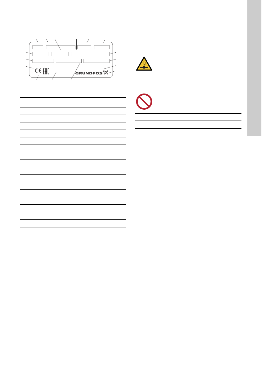
The tanks are supplied from the factory
with a precharge pressure. See the tank
nameplate.

English (GB)
9
6.3 Identification
6.3.1 Nameplate
Fig. 4 Example of a nameplate
7. Servicing the product
7.1 Maintaining the product
Checking the precharge pressure:
• Follow the instructions in section 4.2 Adjusting
the precharge pressure.
Performing visual external check:
1. Is corrosion visible?
2. Are scratches or dents visible?
In case of serious damage, contact your nearest
Grundfos company.
TM07 0427 5017
Pos. Description
1 Product number
2 Type designation
3 Total tank volume [L/Gallon]
4 Effective tank volume [L/Gallon]
5 Serial number
6 Model number
7 Factory-set precharge pressure
8 Test pressure
9 Country of origin
10 Manufacturer
11 Maximum system pressure
12 Production site
13 Notified body
14 Markings and approvals
15 Maximum operating temperature
16 Production code (year and week)
DK - 8850 Bjerringbro, Denmark
Part no. Type Serial No. Model No.
Prod. year/week Nominal Volume Effective Volume Factory Precharge
Max. Temperature(TS) Max. Working pressure(PS) Test pressure:
C / F bar / psi
bar / psi
bar / psi
WRAS Manufactured for GRUNDFOS by
xxxxxxxxxxxx
xxxxxxxxxx
xxxxxxxxxxx Made in XXXXXXX
xxxx
123 5 6
7
8
9
10
12 1113
14
15
16
4
CAUTION
Pressurised system
Minor or moderate personal injury
- Make sure there is no pressure on the
tank before starting any work on the
tank.
- Release all air pressure and empty all
water from the tank before dismantling
parts exposed to pressure.
Do not use a tank with signs of damage,
such as dents, leakage or corrosion.
Precharge pressure check every six months
Visual external check every five years

English (GB)
10
8. Fault finding the product
9. Technical data
See the tank nameplate.
10. Disposing of the product
This product or parts of it must be disposed of in an
environmentally sound way:
1. Use the public or private waste collection service.
2. If this is not possible, contact the nearest
Grundfos company or service workshop.
CAUTION
Pressurised system
Minor or moderate personal injury
- Make sure there is no system pressure
on the tank before starting any work on
the product.
- Release all air pressure and empty all
water from the tank before dismantling
parts exposed to pressure.
Fault Cause Remedy
1. Water escapes
during the
precharge
pressure check.
a) The bladder is defective. The tank
is full of water.
Check the air valve mounted on the tank. If
water escapes when the valve pin is
pushed down, the bladder has burst.
Replace the tank or the bladder.
2. Drained water is
rusted, calcified
or has solid
deposits.
a) The bladder is defective. The bladder is torn or has burst. Replace
the tank or the bladder.
b) The tank is blocked. Check the tank drainage plug and the tank
outlet connection. If it is difficult to drain
the tank, the tank is blocked by a collapsed
or burst bladder or by sediment. Replace
the tank or the bladder.

(BG)
11
Български (BG)
Grundfos GT-U+.
1-5
,
.
6-10
, ,
.
.
1.
1.1
,
Grundfos
-.
:
1. 11
1.1 11
1.2 12
2. 12
2.1 12
3. 12
3.1 12
3.2 12
3.3
13
4. 14
4.1 14
4.2
14
5. 15
5.1 15
5.2 15
6. 15
6.1 15
6.2 15
6.3 15
7. 16
7.1 16
8.
17
9. 17
10. 17
.
.
,
.
,
.
,
.
.
-
.

(BG)
12
1.2
,
Grundfos
-.
2.
2.1
:
1. ,
. ,
Grundfos.
2.
. ,
.
3.
3.1
,
.
- ,
.
.
.
.
3.1.1
.
.
3.2
,
.
,
,
.
,
-:
1. .
2. , .
3. .
4. , .
5.
.
.
,
.
,
, ,
.
.
,
.
.
,
.
-
.
.
.
,
, .

(BG)
13
3.2.1
.
. , ,
. ,
.
. 1
3.2.2
.
. 2
3.2.3
.
3.2.4
,
.
. 3
3.3
,
.
4.2 Настройване на
предварителното налягане на зареждане.
TM06 7710 3716
-
.
-
.
,
.
TM06 7626 3616
.
1
2
1 2
TM07 0426 5017
,
.

(BG)
14
4.
4.1
.
.
:
• 0,9 x
< 2 bar (30 psi).
• 0,7 x
> 2 bar (30 psi).
• 0,7 x
.
4.1.1
.
•
.
•
.
4.2
,
.
1. .
2.
.
,
.
3.
.
.
4. .
4.2.1
4 bar (58 psi)
4 bar (58 psi),
:
1. .
2. .
,
,
3 bar (44 psi),
.
3.
- 3 bar (44
psi).
.
4 bar (58 psi).
,
.
-
, ,
.
-
.
-
.
.
.

(BG)
15
5.
5.1
. 3.2.2 Повдигане на резервоара
5.2
,
, .
,
.
6.
GT-U+
100 3000
10, 16 25 bar.
.
.
6.1
,
.
GT-U+
:
• :
, ,
, .
• :
,
,
.
•
,
.
6.2
:
• , .
• :
,
.
• 50 % .
6.3
6.3.1
. 4
TM07 0427 5017
.
1
2
3 [L/]
4
[L/]
5
6
7
8
9
10
11
12
13
14
15
16 (
)
DK - 8850 Bjerringbro, Denmark
Part no. Type Serial No. Model No.
Prod. year/week Nominal Volume Effective Volume Factory Precharge
Max. Temperature(TS) Max. Working pressure(PS) Test pressure:
C / F bar / psi
bar / psi
bar / psi
WRAS Manufactured for GRUNDFOS by
xxxxxxxxxxxx
xxxxxxxxxx
xxxxxxxxxxx Made in XXXXXXX
xxxx
123 5 6
7
8
9
10
12 1113
14
15
16
4

(BG)
16
7.
7.1
:
•
4.2 Настройване на предварителното
налягане на зареждане.
:
1. ?
2.
?
- Grundfos.
-
, ,
.
-
,
, .
,
, .

(BG)
17
8.
9.
.
10.
, ,
,
:
1.
.
2. ,
Grundfos.
-
, ,
.
-
,
, .
1.
.
a) .
. ,
.
,
.
.
2.
,
.
a) . .
.
b) .
.
,
.
.

eština (CZ)
18
Čeština (CZ) Montážní a provozní návod
Peklad originální anglické verze
Tento montážní a provozní návod popisuje tlakové
nádrže GT-U+.
Kapitoly 1-5 poskytují informace požadované
kbezpenému rozbalení, instalaci a uvedení
výrobku do provozu.
Kapitoly 6-10 poskytují informace o výrobku,
servisních pracích, hledání chyb a likvidaci výrobku.
OBSAH
Strana
1. Obecné informace
1.1 Prohlášení o nebezpenosti
Symboly a prohlášení o nebezpenosti uvedená níže
se mohou vyskytnout v montážních a instalaních
pokynech k výrobkm Grundfos a v bezpenostních
a servisních pokynech.
Prohlášení o nebezpenosti jsou strukturována
následujícím zpsobem:
1. Obecné informace 18
1.1 Prohlášení o nebezpenosti 18
1.2 Poznámky 19
2. Píjem výrobku 19
2.1 Kontrola výrobku 19
3. Instalace výrobku 19
3.1 Umístní 19
3.2 Mechanická instalace 19
3.3 Instalace více nádrží 20
4. Spouštní výrobku 20
4.1 Plnicí tlak 20
4.2 Nastavení plnicího tlaku 21
5. Manipulace s výrobkem a jeho
skladování 21
5.1 Manipulace s výrobkem 21
5.2 Skladování výrobku 21
6. Pedstavení výrobku 21
6.1 Úel použití 21
6.2 erpané kapaliny 21
6.3 Identifikace 22
7. Servis výrobku 22
7.1 Údržba výrobku 22
8. Hledání chyb výrobku 23
9. Technické údaje 23
10. Likvidace výrobku 23
Ped instalací si pette tento dokument.
Pi instalaci a provozování je nutné
dodržovat místní pedpisy a uznávané
osvdené postupy.
NEBEZPEÍ
Oznauje nebezpenou situaci, která
(pokud se jí nepedejde) bude mít za
následek smrt nebo újmu na zdraví.
VAROVÁNÍ
Oznauje nebezpenou situaci, která
(pokud se jí nepedejde) by mohla mít za
následek smrt nebo újmu na zdraví.
UPOZORNNÍ
Oznauje nebezpenou situaci, která
(pokud se jí nepedejde) by mohla mít za
následek menší nebo stední újmu na
zdraví.
SIGNÁLNÍ SLOVO
Popis nebezpeí
Následky ignorování varování.
- Akce, jak nebezpeí pedejít.

eština (CZ)
19
1.2 Poznámky
Symboly a poznámky uvedené níže se mohou
vyskytnout v montážních a instalaních pokynech k
výrobkm Grundfos a v bezpenostních a servisních
pokynech.
2. Píjem výrobku
2.1 Kontrola výrobku
Pi píjmu výrobku provete následující:
1. Zkontrolujte, že výrobek odpovídá objednávce.
Pokud výrobek objednávce neodpovídá, obrate
se na spolenost Grundfos.
2. Zkontrolujte, zda nejsou patrná viditelná
poškození. Pokud jsou patrná njaká viditelná
poškození, kontaktujte pepravní spolenost.
3. Instalace výrobku
3.1 Umístní
Nádrž instalujte na suché a kryté místo, kde
pípadná netsnost nezpsobí poškození vodou.
Nádrž instalujte na výtlanou stranu erpadla a co
nejblíže k erpadlu, aby se snížily ztráty tením.
Musí být možná kontrola nádrže ze všech stran.
Plnicí ventil plynu a typový štítek musejí být
viditelné.
Je nutno zamezit kontaktu nádrže se všemi okolními
stnami nebo tvrdými povrchy.
3.1.1 Umístní tepelné expanzní nádoby
Tepelná expanzní nádrž musí být umístna na
výtlané stranerpadla a na vratné stranohívae
vody.
Tepelnou expanzní nádrž nainstalujte v nezamrzající
místnosti.
3.2 Mechanická instalace
Nádrž nainstalujte tak, aby nebyla namáhána
potrubím. Jestliže se mohou vyskytnout vibrace,
doporuujeme nádrž nainstalovat tak, aby byly
vibrace absorbovány.
Doporuujeme postupovat podle následujících
krok, které jsou podrobnpopsány níže:
1. Nádrž zvednte a umístte.
2. Podle poteby ji spuste.
3. Nádrž upevnte.
4. Pipojte potrubí, armatury a ventily.
5. Zkontrolujte plnicí tlak a upravte jej podle
poteby.
Tyto pokyny dodržujte pro výrobky odolné
proti výbuchu.
Modrý nebo šedý kruh s bílým grafickým
symbolem oznauje, že je nutná akce, aby
se pedešlo nebezpeí.
ervený nebo šedý kruh s diagonálním
peškrtnutím, a pípadnerným grafickým
symbolem, oznauje, že se akce nesmí
provést nebo že musí být zastavena.
Pokud nebudou tyto pokyny dodrženy,
mohlo by dojít k poruše nebo poškození
zaízení.
Tipy a zaízení k usnadnní práce.
Instalace musí být provedena v souladu
s místními pedpisy.
Ped instalací nádrže zkontrolujte
maximální provozní tlak a teplotu na
typovém štítku nádrže.
Maximální tlak v soustavmusí být nižší
nebo stejný jako maximální provozní tlak
nádrže.
Pi bžném provozu nebo pi kontrole
systému nesmí být pekroen maximální
provozní tlak.
Žádná další zatížení z potrubní soustavy
nebo zaízení nejsou povoleny.
Nepoužívejte nádrž se známkami
poškození, jako jsou promáknutí,
netsnost nebo koroze.

eština (CZ)
20
3.2.1 Základ
Nádrž umístte na rám ve svislé poloze na pevné
a rovné podlaze nebo na základu.
Nádrž na podlahu nebo základ upevnte pomocí
šroub. Použijte šrouby, podložky a matice, které
jsou vhodné pro povrch podlahy nebo základový
rám. K upevnní nádrže použijte všechny otvory
vrámu.
Obr. 1 Píklad instalace na podlaze
3.2.2 Zdvihání nádrže
Pi manipulaci dbejte na to, abyste nádrž
nepoškodili.
Obr. 2 Zdvihání nádrže
3.2.3 Pojistný ventil
Doporuujeme instalovat vhodný pojistný ventil.
3.2.4 Uzavírací armatura
Mezi tlakovou nádrž a potrubí doporuujeme
instalovat uzavírací armaturu, abyste pi servisních
pracích mohli tlakovou nádrž izolovat.
Obr. 3 Uzavírací armatura
3.3 Instalace více nádrží
Nádrže musí být instalovány na kolektor, aby byl
zajištn stejný vyvážený tlak pro všechny nádrže.
Plnicí tlak v jednotlivých nádržích nastavte podle
popisu v kapitole 4.2 Nastavení plnicího tlaku.
4. Spouštní výrobku
4.1 Plnicí tlak
Správný plnicí tlak je nutný pro správný výkon
nádrže.
Plnicí tlak musí být nastaven v závislosti na aktuální
aplikaci a instalaci erpadla.
Doporuené plnicí tlaky:
•0,9×zapínací pro erpadla s pevnými otákami
s diferenním tlakem < 2 bar (30 psi).
•0,7×vypínací pro erpadla s pevnými otákami
s diferenním tlakem > 2 bar (30 psi).
•0,7×požadovaná hodnota pro promnné otáky
erpadel.
TM06 7710 3716
NEBEZPEÍ
Nebezpeí rozdrcení
Smrt nebo závažná újma na zdraví
- Použijte zvedací jeáb nebo podobné
zvedací zaízení.
-Pi manipulaci s erpadlem používejte
ochrannou obuv.
Pi zvedání nádrže používejte všechny
zvedací oka na nádrži.
TM06 7626 3616
Pol. Popis
1 Správné zvedání
2 Nesprávné zvedání
12
TM07 0426 5017
Aby soustava správnfungovala, musí mít
všechny nádrže stejný plnicí tlak.
Rozdíl mezi plnicím tlakem a tlakem
v soustavnesmí nikdy pekroit 4 bar (58
psi). Pokud je teba snížit tlak v soustav,
je nutno nádrž odpojit nebo vyprázdnit.
Table of contents
Languages:
Other Grundfos Water Heater manuals
Popular Water Heater manuals by other brands

Kospel
Kospel EPJ.P Series installation instructions

Propex
Propex Malaga 3 Installation & operation instructions

Austria Email
Austria Email SISS 350/100 Operating and mounting instructions

Triton
Triton SPT303IR manual

Lochinvar
Lochinvar Copper Tube Water Heater Limited warranty

Omega
Omega OME 412 Installation manual and owner's guide

Webasto
Webasto Thermo Top E installation instructions

Siddons Solarstream
Siddons Solarstream 264SSBD Installation and user manual

Noritz
Noritz NC250-SV-ASME owner's guide

NTI
NTI GF 200 installation manual

STIEBEL ELTRON
STIEBEL ELTRON DHB 18 STi Operating and installation

Benchmark
Benchmark PulsaCoil 2000 Series Design, installation and servicing instructions