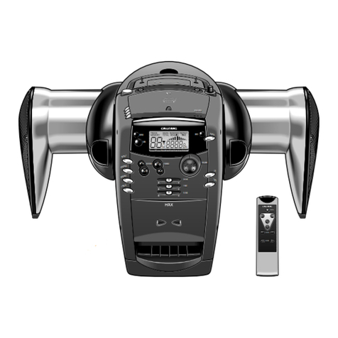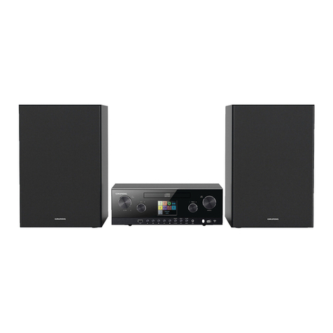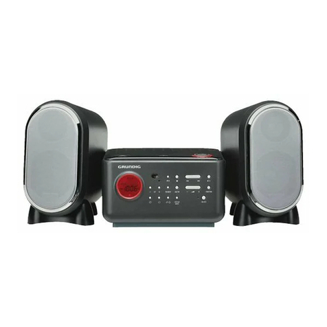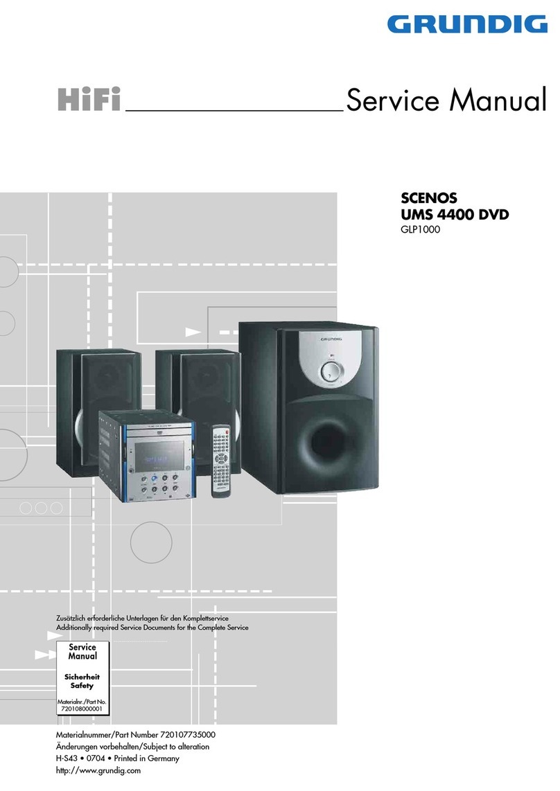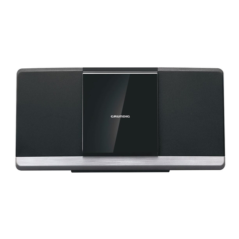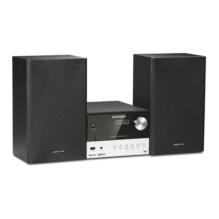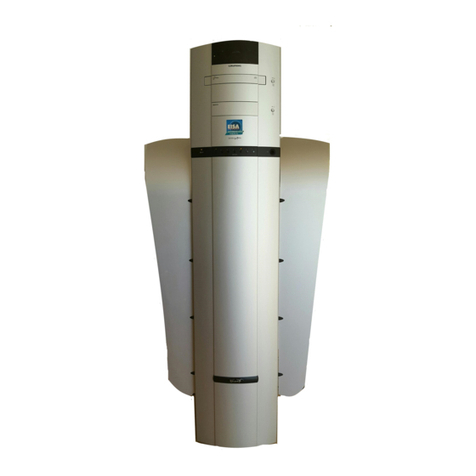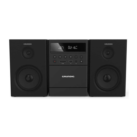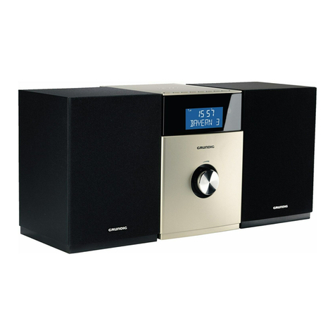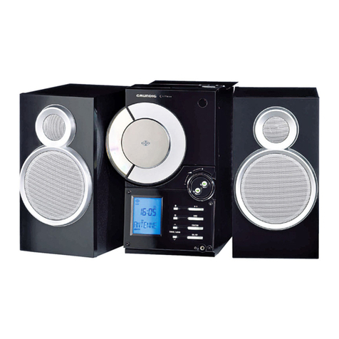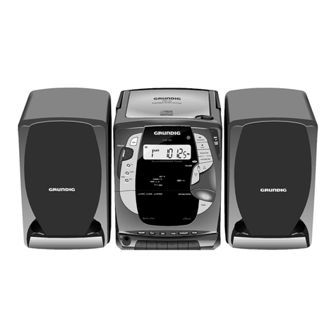
GRUNDIG Service Ovation CDS 6380 S
1 - 2
Table of Contents Page
General Section.................................... 1-2…1-6
Measuring Instruments / Equipment ............................................ 1-2
Technical Data ............................................................................. 1-3
Service Hints ................................................................................ 1-3
Disassembly Instructions ............................................................. 1-4
Adjustment Procedures................................2-2
Circuit Diagrams and
Layout of the PCBs ............................ 3-1…3-14
Block Diagram.............................................................................. 3-1
Wiring Diagram ............................................................................ 3-2
Circuit Diagrams:
Tuner PCB ............................................................................... 3-4
MCU / CD Servo PCB .............................................................. 3-6
Reset PCB ............................................................................... 3-6
CD Door PCB........................................................................... 3-6
Audio PCB.............................................................................. 3-10
Power Supply PCB................................................................. 3-10
Headphone PCB .................................................................... 3-10
LINE PCB ............................................................................... 3-10
Display PCB ........................................................................... 3-12
LED PCBs .............................................................................. 3-12
IR Receiver PCB .................................................................... 3-12
Key PCB................................................................................. 3-12
Layout of the PCBs:
Tuner PCB ............................................................................... 3-3
MCU/CD Servo PCB ................................................................ 3-8
Reset PCB ............................................................................... 3-8
CD Door PCB........................................................................... 3-8
Audio PCB................................................................................ 3-9
Power Supply PCB................................................................... 3-9
Headphone PCB ...................................................................... 3-9
LINE PCB ................................................................................. 3-9
LED PCBs .............................................................................. 3-12
IR Remote PCB...................................................................... 3-12
Key PCB................................................................................. 3-13
Display PCB ........................................................................... 3-14
Exploded View and
Spare Parts List.................................... 4-1…4-3
Inhaltsverzeichnis Seite
Allgemeiner Teil ................................... 1-2…1-6
Messgeräte / Messmittel .............................................................. 1-2
Technische Daten ........................................................................ 1-3
Servicehinweise ........................................................................... 1-3
Ausbauhinweise........................................................................... 1-4
Abgleichvorschriften ....................................2-1
Schaltpläne und
Platinenabbildungen.......................... 3-1…3-14
Blockschaltplan ............................................................................ 3-1
Verdrahtungsplan......................................................................... 3-2
Schaltpläne:
Tuner-Platte ............................................................................. 3-4
MCU-/CD-Servo-Platte............................................................. 3-6
Reset-Platte ............................................................................. 3-6
CD-Klappen-Platte ................................................................... 3-6
Audio-Platte............................................................................ 3-10
Netzteil-Platte......................................................................... 3-10
Kopfhörer-Platte ..................................................................... 3-10
LINE-Platte............................................................................. 3-10
Display-Platte ......................................................................... 3-12
LED-Platten ............................................................................ 3-12
IR-Empfänger-Platte .............................................................. 3-12
Tasten-Platte .......................................................................... 3-12
Platinenabbildungen:
Tuner-Platte ............................................................................. 3-3
MCU-/CD-Servo-Platte............................................................. 3-8
Reset-Platte ............................................................................. 3-8
CD-Klappen-Platte ................................................................... 3-8
Audio-Platte.............................................................................. 3-9
Netzteil-Platte........................................................................... 3-9
Kopfhörer-Platte ....................................................................... 3-9
LINE-Platte............................................................................... 3-9
LED-Platten ............................................................................ 3-12
IR-Empfänger-Platte .............................................................. 3-12
Tasten-Platte .......................................................................... 3-13
Display-Platte ......................................................................... 3-14
Explosionszeichnung und
Ersatzteilliste ........................................ 4-1…4-3
AllgemeinerTeil
Messgeräte / Messmittel
Mess- / Wobbel-Sender
Klirrfaktor-Messgerät
Oszilloskop
Digital-Voltmeter
NF-Voltmeter
Frequenzzähler
General Section
Measuring Instruments / Equipment
Signal / Sweep Generator
Distortion Meter
Oscilloscope
Digital Voltmeter
AF Voltmeter
Frequency Counter
Es gelten die Vorschriften und Sicherheitshinweise
gemäß dem Service Manual "Sicherheit", Material-
nummer720108000000,sowiezusätzlichdieeventu-
ell abweichenden, landesspezifischen Vorschriften!
The regulations and safety instructions shall be valid
as provided by the "Safety" Service Manual, part
number 720108000000, as well as the respective
national deviations!

