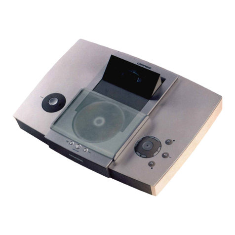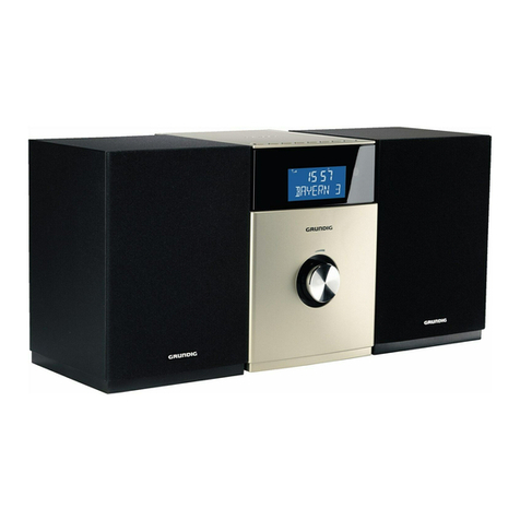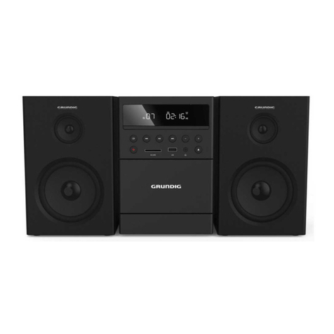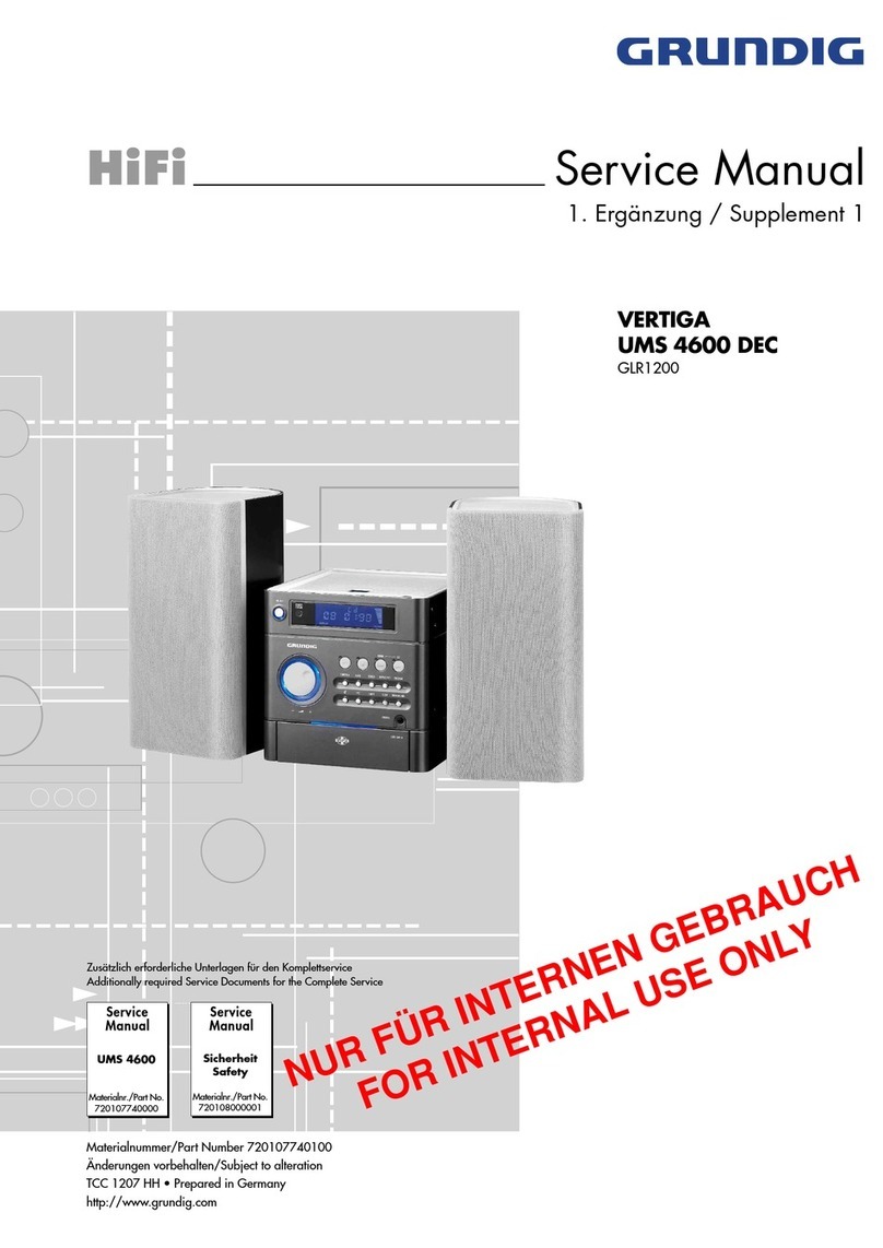
GRUNDIG Service VERTIGA UMS 6300
1 - 2
Es gelten die Vorschriften und Sicherheitshin-
weise gemäß dem Service Manual "Sicherheit",
Materialnummer 720108000001, sowie zusätz-
lich die eventuell abweichenden, landes-
spezifischen Vorschriften!
The regulations and safety instructions shall be
validasprovidedbythe"Safety"ServiceManual,
part number 720108000001, as well as the re-
spective national deviations!
Table of Contents
Page
General Section ............................ 1 - 2 … 1 - 10
Measuring Instruments / Equipment .......................................... 1 - 2
Technical Data ........................................................................... 1 - 3
Service Hints .............................................................................. 1 - 3
Disassembly Hints ..................................................................... 1 - 4
Operating Hints .......................................................................... 1 - 8
Adjustment Procedures.............................. 2 - 2
Circuit Diagrams
and Layout of PCBs ..................... 3 - 1 … 3 - 17
Block Diagram ............................................................................ 3 - 1
Wiring Diagram .......................................................................... 3 - 2
Circuit Diagrams:
Power Supply ......................................................................... 3 - 3
Amplifier Board ....................................................................... 3 - 4
MCU Board ............................................................................ 3 - 7
Headphone Board ................................................................ 3 - 12
Operation Board ................................................................... 3 - 12
CD Compartment Position Sensors ..................................... 3 - 12
Display Board ....................................................................... 3 - 13
Tuner Board ......................................................................... 3 - 16
Layout of the PCBs:
Power Supply ......................................................................... 3 - 3
Amplifier Board ....................................................................... 3 - 6
MCU Board .......................................................................... 3 - 11
Headphone Board ................................................................ 3 - 12
Operation Board ................................................................... 3 - 12
CD Compartment Position Sensors ..................................... 3 - 12
Display Board ....................................................................... 3 - 15
Tuner Board ......................................................................... 3 - 15
Exploded View and
Spare Parts List.............................. 4 - 1 … 4 - 4
Inhaltsverzeichnis
Seite
Allgemeiner Teil ............................. 1 - 2 … 1 - 7
Messgeräte / Messmittel ............................................................ 1 - 2
Technische Daten ...................................................................... 1 - 3
Servicehinweise ......................................................................... 1 - 3
Ausbauhinweise ......................................................................... 1 - 4
Bedienhinweise .......................................................................... 1 - 5
Abgleichvorschriften .................................. 2 - 1
Schaltpläne
und Platinenabbildungen ............ 3 - 1 … 3 - 17
Blockschaltplan .......................................................................... 3 - 1
Verdrahtungsplan....................................................................... 3 - 2
Schaltpläne:
Netzteil ................................................................................... 3 - 3
Verstärker-Platte .................................................................... 3 - 4
MCU-Platte ............................................................................. 3 - 7
Kopfhörer-Platte ................................................................... 3 - 12
Bedien-Platte ........................................................................ 3 - 12
CD-Fach-Position-Sensoren ................................................ 3 - 12
Display-Platte ....................................................................... 3 - 13
Tuner-Platte ......................................................................... 3 - 16
Platinenabbildungen:
Netzteil ................................................................................... 3 - 3
Verstärker-Platte .................................................................... 3 - 6
MCU-Platte ........................................................................... 3 - 11
Kopfhörer-Platte ................................................................... 3 - 12
Bedien-Platte ........................................................................ 3 - 12
CD-Fach-Position-Sensoren ................................................ 3 - 12
Display-Platte ....................................................................... 3 - 15
Tuner-Platte ......................................................................... 3 - 15
Explosionszeichnung und
Ersatzteilliste .................................. 4 - 1 … 4 - 4
Allgemeiner Teil
Messgeräte / Messmittel
Mess-Sender Wobbelsender
Oszilloskop Digitalvoltmeter
Klirrfaktormessgerät
General Section
Measuring Instruments / Equipment
Signal generator Sweep generator
Oscilloscope Digital voltmeter
Distortion meter
