1 - 2 GRUNDIG Service
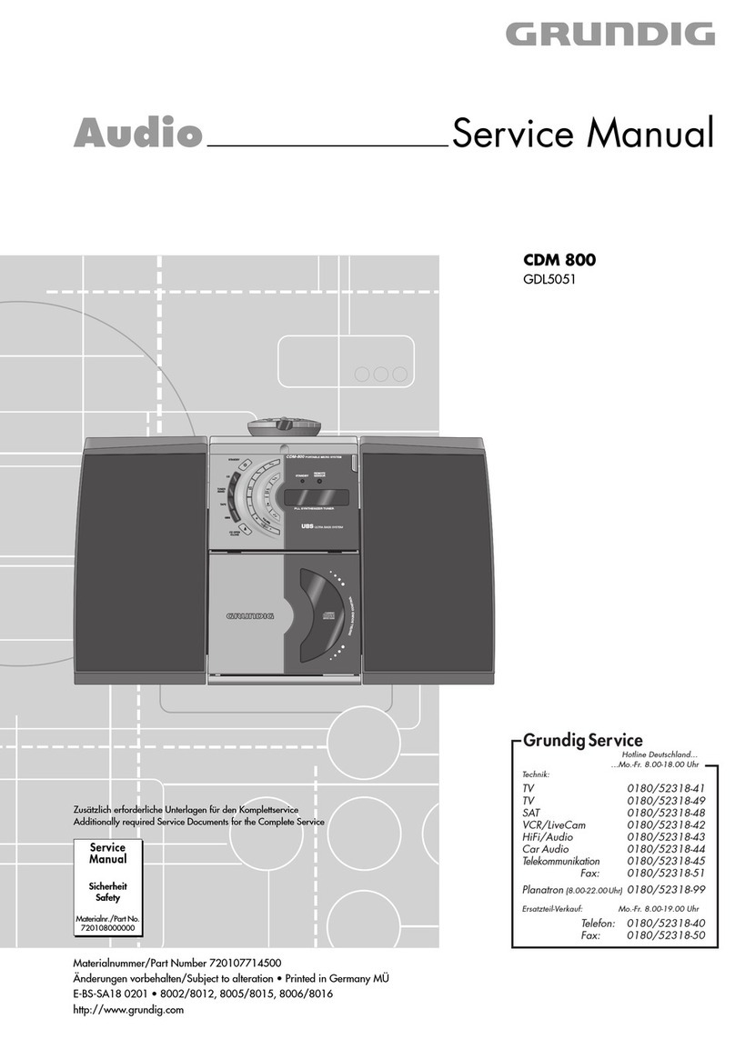
Allgemeiner Teil / General Section M 19-C / M 29-C
Es gelten die Vorschriften und Sicherheitshin-
weise gemäß dem Service Manual "Sicherheit",
Materialnummer720108000000,sowiezusätz-
lich die eventuell abweichenden, landes-
spezifischen Vorschriften!
The regulations and safety instructions shall be
validasprovidedbythe"Safety"ServiceManual,
part number 72010 800 0000, as well as the
respective national deviations!
Table of Contents
Page
General Notes..............................................1 - 2
General Section............................ 1 - 3 … 1 - 21
Technical Data ........................................................................... 1 - 3
Operating Instructions................................................................ 1 - 9
Disassembly Instructions ......................................................... 1 - 15
Adjustment Procedures..................2 - 3 ... 2 - 4
Layout of the PCBs
and Circuit Diagrams ................... 3 - 1 … 3 - 41
Block Diagram............................................................................ 3 - 1
Wiring Diagram .......................................................................... 3 - 2
Circuit Diagrams:
Mains Unit Board.................................................................... 3 - 4
CD Key Board, Control Board .............................................. 3 - 10
Headphone Board, Main Board............................................ 3 - 14
Tuner Part ............................................................................ 3 - 20
Amplifier Board..................................................................... 3 - 24
Cassette Board .................................................................... 3 - 30
CD Board ............................................................................. 3 - 34
Display ....................................................................................... 3 - 6
Layout of the PCBs:
Mains Unit Board.................................................................... 3 - 6
CD Key Board, Control Board ................................................ 3 - 8
Headphone Board, Main Board............................................ 3 - 18
Amplifier Board, Cassette Board.......................................... 3 - 28
CD Board ............................................................................. 3 - 32
IC Block Diagrams ................................................................... 3 - 36
Spare Parts Lists and
Exploded Views............................ 4 - 1 … 4 - 10
Inhaltsverzeichnis
Seite
Allgemeine Hinweise ..................................1 - 2
Allgemeiner Teil ........................... 1 - 3 … 1 - 21
Technische Daten ...................................................................... 1 - 3
Bedienhinweise.......................................................................... 1 - 4
Ausbauhinweise....................................................................... 1 - 15
Abgleichvorschriften ......................2 - 1 ... 2 - 2
Platinenabbildungen
und Schaltpläne ........................... 3 - 1 … 3 - 41
Blockschaltplan .......................................................................... 3 - 1
Verdrahtungsplan....................................................................... 3 - 2
Schaltpläne:
Netzteilplatte .......................................................................... 3 - 4
CD-Tastenplatte, Steuerplatte.............................................. 3 - 10
Kopfhörerplatte, Hauptplatte ................................................ 3 - 14
Tuner-Teil ............................................................................. 3 - 20
Verstärkerplatte .................................................................... 3 - 24
Cassetten-Platte................................................................... 3 - 30
CD-Platte.............................................................................. 3 - 34
Display ....................................................................................... 3 - 6
Platinenabbildungen:
Netzteilplatte .......................................................................... 3 - 6
CD-Tastenplatte, Steuerplatte................................................ 3 - 8
Kopfhörerplatte, Hauptplatte ................................................ 3 - 18
Verstärkerplatte, Cassetten-Platte ....................................... 3 - 28
CD-Platte.............................................................................. 3 - 32
IC-Blockdiagramme ................................................................. 3 - 36
Ersatzteillisten und
Explosionszeichnungen .............. 4 - 1 … 4 - 10
Allgemeine Hinweise
Materialnummern
Durch die EDV-Umstellung wurden die bisherigen 10-stelligen
Materialnummern auf 12-stellige geändert.
Beispiel: bisher: 29504-111.22
neu: 29504 111 2200
Während der Umstellphase können im Service Manual beide
Schreibweisen vorkommen.
Meßgeräte
Beachten Sie bitte das GRUNDIG Meßtechnik-Programm, das Sie
unter folgender Adresse erhalten:
General Notes
Part Numbers
Due to the conversion of the EDP system, the previous 10-digit part
numbers were change to 12-digit numbers.
Example: previous: 29504-111.22
new: 29504 111 2200
During the conversion of the system, either form may be found in
the Service Manual.
Test Equipment
Please note the GRUNDIG Catalog "Test and Measuring Equipment"
obtainable from:
Grundig AG Geschäftsbereich Instruments Test- und Meßsysteme
Würzburger Str. 150, D-90766 Fürth
Tel.: 0911 / 703-4118, Fax: 0911 / 703-4130
