manuals.online logo
Brands
  1. Home
  2. •
  3. Brands
  4. •
  5. Kenwood
  6. •
  7. Tuner
  8. •
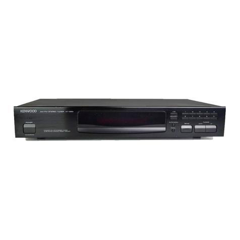
  9. Kenwood KT-87 User manual

Kenwood KT-87 User manual

AM/FM
STEREO
TUNER
KT-87
INSTRUCTION
MANUAL
KENWOOD
Introduction
Your
choice
of
this
product
indicates
that
you
are
a
devotee
to
excellence
in
sound
reproduction.
We
appreciate
your
patronage
and
take
pride
in
the
long
tradition
of
quality
components.
So
that
you
can
get
the
most
out
of
your
unit,
we
suggest
that
you
take
the
time
to
read
through
this
manual
before
you
hook
up
and
operate
your
system.
This
will
acquaint
you
with
operating
features,
and
system-connection
con-
siderations,
so
that
your
listening
pleasure
will
be
enhanced
right
from
the
start.
You
will
notice
that
in
all
aspects
of
_
Planning,
engineering,
styling,
operating
convenience
and
adaptability,
we
have
sought
to
anticipate
your
needs
and
desires.
Keep
this
manual
handy
for
future
reference.
For
your
records
Record
the
serial
number,
found
on
the
back
of
the
unit,
in
the
spaces
designated
on
the
warranty
card,
and
in
the
space
provided
below.
Refer
to
the
model
and
serial
numbers
whenever
you
call
upon
your
dealer
for
informa-
tion
or
service
on
this
product.
Model
KT-87
Serial
Number
Unpacking
Unpack
the
unit
carefully
and
make
sure
that
all
acces-
sories
and
cables
are
put
aside
so
they
will
not
be
lost.
Examine
the
unit
for
any
possibility
of
shipping
damage.
If
your
unit
is
damaged
or
fails
to
operate,
notify
your
dealer
immediately.
If
your
unit
was
shipped
to
you
directly,
notify
the
shipping
company
without
delay.
Only
the
consignee
(the
person
or
company
receiving
the
unit)
can
file
a
claim
against
the
carrier
for
shipping
damage.
We
recommend
that
you
retain
the
original
carton
and
packing
materials
for
use
should
you
transport
or
ship
the
unit-in
the
future.
@©PRINTED
IN
J.
8
JAPAN
B50-8674-00(K,P,U,UE,M)(G)
88/12
11
109
654
1
7
Note
to
CATV
system
installer:
This
reminder
is
provided
to
call
the
CATV
system
install-
er’s
attention
to
Article
820
~
22
of
the
NEC
that
provides
guidelines
for
proper
grounding
and,
in
particular,
specifies
that
the
cable
ground
shall
be
connected
to
the
grounding
system
of
the
building,
as
close
to
the
point
of
cable
entry
as
practical.
Accessories
RCA
pin
plug
cord
........
one
e
etebee
pO
RE
a
se
cseies
1
AM
loop
antenna
oe
1
AM
loop
antenna
stand
1
FM
T
shaped
antenna
ooiccteiceicceseessstecets
tives
becssesseestverseseee
1
Contents
A
Before
applying
power
AN
Safety
precautions...
_
2
Important
safeguards
:
SYStOM
CONNECTIONS...
eee
eccecscssessesesstssessectesessesveseeceees
5
Caution:
Read
the
following
pages
marked
in
A\
carefully
to
keep
your
Safety.
Controls
and
indicators...
esesstbeseeecnsesioeesseesees
8
Operating
instructions
nn.
2
ate,
.
10
In
case
Of
diffiCUlty
oo
cce
clecescstectsesseseessestesceseeees
1:5
SPECINICATONS
Hic
acedcasschaaiersn
chiles
a
esilis.
15

A
Caution:
Read
this
page
carefully
to
keep
your
safety.
Before
applying
power
Important!
U.S.A.
and
Canada
Units
shipped
to
the
U.S.A.
and
Canada
are
designed
for
operation
on
120
V
AC
only.
These
units
are
not
equipped
with
an
AC
voltage
selector
switch
and
the
discussion
of
such
a
switch
that
follows,
should
be
disregarded.
All
other
countries
Units
shipped
to
countries
other
than
the
above
countries
are
equipped
with
an
AC
voltage
selector
switch
on
the
rear
panel.
Refer
to
the
following
paragraph
for
the
proper
setting
of
this
switch.
La
AC
voltage
selection
These
units
operates
on
110-120
volts
or
220-240
volts
AC.
The
AC
voltage
selector
switch
of
the
amplifier
is
set
to
the
voltage
that
prevails
in
the
area
to
which
the
units
was
shipped.
Before
connecting
the
power
cord
to
your
AC
outlet,
make
sure
that
the
setting
position
of
this
switch
matches
your
line
voltage.
If
not,
it
must
be
set
to
your
voltage
in
accordance
with
the
following
direction.
Note:
Our
warranty
does
not
cover
damage
caused
by
excessive
line
voltage
due
to
improper
setting
of
the
AC
voltage
selector
switch.
Safety
precautions
AC110-120VV4
BAC220-240VV
AC110-120VV4
BAC220-240VU
Switch
lever
Safety
precaution
for
AC
plug
(For
ee
U.S.A.
and
Canada)
*
CAUTION:
To
PREVENT
ELECTRIC
SHOCK
DO
NOT
USE
THIS
(POLARIZED)
PLUG
WITH
AN
EXTENSION
CORD,
This
shows
switch
Thik-<howe-awheh
RECEPTACLE
OR
OTHER
OUTLET
UNLESS
THE
BLADES
lever
is
locked
in
lever
is
locked
in
CAN
BE
FULLY
INSERTED
TO
PREVENT
BLADE
EXPOSURE.
110-120VV
position.
220-240V/V
position.
|
WARNING:
M
itch
lever
to
match
your
line
voltage
athe
cen
screw
driver
or
other
pointed
tool.
TO
PREVENT
Fl
RE
OR
ELECTRIC
SHOCK,
DO
NOT
EXPOSE
THIS
APPLIANCE
TO
a
AC
voltage
selector
switch
RAIN
OR
MOISTURE.
RISK.OF
ELECTRIC
SHOCK
REMOVE
COVER
(OR
BACK).
NO
USER-SERVICEABLE
PARTS
INSIDE.
DO-NOT
OPEN:
REFER
SERVICING
TO
QUALIFIED
SERVICE
PERSONNEL.
;
[CAUTION
—_|
f
CAUTION:
TO
REDUCE
THE
RISK
OF
ELECTRIC
SHOCK,
DO
NOT
THE
LIGHTNING
FLASH
WITH
ARROWHEAD
SYMBOL,
WITHIN
AN
EQUILATERAL
TRIANGLE,
IS
INTENDED
TO
ALERT
THE
USER
TO
THE
PRESENCE
OF
UNINSULATED
“DANGEROUS
VOLTAGE”
WITHIN
THE
PRODUCT’S
ENCLOSURE
THAT
MAY
BE
OF
SUFFICIENT
MAGNITUDE
TO
CONSTITUTE
A
RISK
OF
ELECTRIC
SHOCK
TO
PERSONS.
THE
EXCLAMATION
POINT
WITHIN
AN
EQUILATERAL
TRIANGLE
IS
INTENDED
TO
ALERT
THE
USER
TO
THE
PRESENCE
OF
IMPORTANT
OPERATING
AND
MAINTENANCE
(SERVICING)
INSTRUCTIONS
IN
THE
LITERATURE
ACCOMPANYING
THE
APPLIANCE.
2...
.KT-87
(K)
Important
safeguards
Please
read
all
of
the
safety
and
operating
instructions
before
operating
this
unit.
For
best
results,
follow
all
warnings
placed
on
the
unit
and
‘adhere
to
the
operating
and
use
instructions.
These
safety
and
operating
instructions
should
be
retained
for
future
reference.
1.
Power
sources
—
The
unit
should
be
connect-
ed
to
a
power
supply
only
of
the
type
described
in
the
operating
instructions
or
as
marked
on
the
appliance.
Power-cord
protection
—
Power-supply
cords
should
be
routed
so
that
they
are
not
likely
to
be
walked
on
or
pinched
by
items
placed
upon
or
against
them.
pay
particular
attention
to
cords
at
plugs,
convenience
receptacles,
and
the
point
where
they
exit
from
the
unit.
Never
pull
or
stretch
the
cord.
Grounding
or
polarization
—
Precautions
that
should
be
taken
so
that
the
grounding
or
polari-
zation
means
of
this
unit
is
not
defeated.
.
Ventilation
—
The
unit
should
be
situated
so
that
its
location
or
position
does
not
interfere
with
its
proper
ventilation.
To
maintain
good
ventilation,
do
not
put
records
or
a
table-cloth
on
the
unit.
Place
the
unit
at
least
10
cm
away
from
the
walls.
Do
not
use
the
unit
on
a
bed,
sofa,
rug
or
similar
surface
that
may
block
the
ventilation
openings.
.
Water
and
moisture
—
The
unit
should
not
be
used
near
water
—
for
example,
near
a
bathtub,
washbowil,
kitchen
sink,
laundry
tub,
in
a
wet
basement,
or
near
a
swimming
pool,
etc.
A\
Caution:
Read
this
page
carefully
to
keep
your
safety.
6.
Temperature
—
The
unit
may
not:
function
properly
if
used
at
extremely
low.
or
freezing
temperatures.
The
ideal
ambient
temperature
is
above
+5°C
(41°F).
.
Heat
-
The
unit
should
be
situated
away
from
heat
sources
such
as
radiators,
heat
registers,
stoves,
or
other
units
(including
amplifiers)
that
produce
heat.
.
Electric
shock
—
Care
should
be
taken
so
that
10.
object
do
not
fall
and
liquid
are
not
spilled
into
the
enclosure
through
openings.
If
a
metal
object,
such
as
a
hair
pin
or
a
needle,
comes
into
contact
with
the
inside
of
this
unit,
a
dangerous
electric
shock
may
result.
For
families
with
children,
never
permit
children
to
put
anything,
especially
metal,
inside
this
unit.
Enclosure
removal
—
Never
remove
the
enclo-
sure.
If
the
internal
parts
are
touched
accidental-
ly,
a
serious
electric
shock
might
occur.
AC
outlets
-
Do
not
connect
other
audio
equipment
with
a
power
consumption
larger
than
that
specified
to
the
AC
outlet
on
the
rear
panel.
Never
connect
other
electrical
units,
such
as
an
iron
or
toaster,
to
it
to
prevent
fire
or
electric
shock.
The
maximum
capacities
indicated
for
the
AC
outlets
on
the
rear
panel
of
the
this
unit
are
as
follows.
1.
SWITCHED
outlets
;
7OOW
2.
UNSWITCHED
outlets
;
100W
KT-87
{K)
3
11.
Magnetic
fields
-
Keep
the
units
away
from
a
source
of
magnetic
fields
such
as
TV
sets,
speaker
systems,
radios,
motorized
toys
or
mag-
netized
objects.
12.
Cleaning
—
Do
notuse
volatile
solvents
such
as
alcohol,
paint
thinner,
gasoline,
benzine,
etc.
to
clean
the
cabinet.
Use
a
clean
dry
cloth.
13.
Nonuse
periods
—
The
power
cord
of
the
unit
should
be
unplugged
from
the
outlet
when
left
unused
for
a
long
period
of
time.
A\
Caution:
Read
this
page-carefully
to
keep
your
safety.
14.
Abnormal
smell
—
If
an
abnormal
smell
or
smoke
is
detected,
immediately
turn
the
power
OFF
and
pull
out
the
power
cord.
Contact
your
dealer
or
nearest
service
station.
POWER
OFF!
Bann
a
eee
ot,
=
—-—_
gi
oor
#4
D
ai
—p}o
Damage
requiring
service
—
The
unit
should
be
serviced
by
qualified
service
personnel
when:
A.
The
power-supply
cord
or
the
plug
has
been
damaged:
or
B.
Objects
have
fallen,
or
liquid
has
been
spilled
into
the
unit;
or
C.
The
unit
has
been
exposed
to
rain;
or
D.
The
unit
does
not
appear
to
operate.
normally
or
exhibits
a
marked
change
in
performance:
or
E.
The
unit
has
been
dropped,
or
the
enclosure
damaged.
15.
16.
Servicing
-
The
user
should
not
attempt
to
service
the
unit
beyond
that
described
in
the
operating
instructions.
All
other
servicing
should
be
referred
to
qualified
service
personnel.
17.
Outdoor
antenna
grounding
-
If
an
outside
antenna
is
connected
to
the
receiver,
be
sure
the
antenna
system
is
grounded
so
as
to
provide
some
protection
against
voltage
surges
and
built
up
static
charges.
Section
810
of
the
National
Electrical
Code,
ANSI/NFPA
No.
70
-
1984,
provides
information
with
respect
to
proper
grounding
of
the
mast
and
supporting
structure,
grounding
of
the
lead-in
wire
to
an
antenna
discharge
unit,
size
of
grounding
conductors,
location
of
antenna-discharge
unit,
connection
to
grounding
electrodes,
and
requirements
for
the
grounding
electrode.
See
Figure.
—
2
Use
No.10
AWG
(5.3
mm?)
copper,
No.8
AWG
(8.4
mm?)
aluminum,
No.17
AWG
(1.0
mm?)
copper-clad
steel
or
bronze
wire,
or
larger,
as
a
ground
wire.
o
Secure
antenna
lead-in
and
ground
wires
to
house
with
stand-off
insulators
spaced
from
4
—
6
feet
(1.22
-—
1.83
m)
apart.
©
Mount
antenna
discharge
unit
as
close
as
possible
to
where
lead-in
enters
house.
4
Use
jumper
wire
not
smaller
than
No.6
AWG
(13.3
mm?)
copper,
or
the
equivalent.
when
a
separate
antenna-grounding
electrode
is
used.
See
NEC
Section
810-2
1(j).
18.
Power
lines
—
An
outdoor
antenna
should
be
located
away
from
power
lines.
Notes:
POWER
LINES
SERVICE
ENTRANCE
CONDUCTORS
STANDOFF
INSULATORS”
MAST
SERVICE
ENTRANCE
EQUIPMENT
ANTENNA
LEAD-IN
WIRE
ANTENNA
DISCHARGE
UNITS
POWER
SERVICE
GROUNDING
ELECTRODE
SYSTEM
{e.g.
interior
metal
water
pipe)
BONDING
JUMPER®
GROUND
CLAMPS
OPTIONAL
ANTENNA
GROUNDING
ELECTRODE
DRIVEN
8
FEET
(2.44
m)
INTO
THE
EARTH
IF
REQUIRED
BY
LOCAL
CODES.
SEE
NEC
SECTION
810-21(f).
FIGURE
EXAMPLE
OF
ANTENNA
GROUNDING
ACCORDING
TO
THE
NATIONAL
ELECTRICAL
CODE
INSTRUCTIONS
CONTAINED
IN
ARTICLE
810
—“RADIO
AND
TELEVISION
EQUIPMENT”
1.
Item
3
is
not
required
except
for
grounded
or
polarized
equipment.
2.
Item
10
is
not
required
except
for
units
provided
with
AC
outlets.
3.
Item
17
and
18
are
not
required
except
for
units
provided
with
antenna
terminals.
4
KT-87
(kK)
System
connections
FM
outdoor
antenna
FM
indoor
antenna
AM
outdoor
antenna
>
AM
loop
antenna
750
coaxial
cable
[3000
feeder
Connect
the
loop
antenna
as
shown.
oo
AGH10=
\20V~
mame
ACZZ0-240V—~
O
swaronen
aw
1300
Ga
Seow
nas?
@
To
AC
outlet
These
switches
are
not
provided
with
the
units
shipped
to
some
areas.
System
control
con-
nection
cord
provided
with
the
amplifier.
Amplifier
Speaker
system
Speaker
system
@
System
control
terminal
A
system
control
terminal
is
provided
on
the
rear
panel,
allowing
the
remote
control
of
the
tuner
when
the
terminal
is
connected
to
the
system
control
terminal
on
the
amplifier.
For
the
remote
control
range
and
control
method,
please
refer
to
the
instruction
manual
of
an
amplifier
equipped
with
the
system
control
terminal
(KC-
207,
for
example).
KT-87
(kK)
5
Output
Signals
from
the
output
jacks
are
fed
to
the
amplifier.
Connection
cables
should
be
plugged
to
the
amplifier
TUNER
or
AUX
jacks.
Shielded
cables
terminated
at
both
ends
with
standard
phono
plugs
are
supplied
with
this
tuner.
AC
outlet
The
AC
outlets
on
the
rear
panel
can
be
used
to
supply
power
to
other
components
in
the
system.
Never
connect
equipment
whose
power
consumption
exceeds
the
maxi-
mum
value
shown
at
each
outlet.
SWITCHED:
This
outlet
supplies
power
when
the
unit
is
set
to
tuner
mode
or
the
built-in
timer
is
activated.
@
The
maximum
capacity
is
7O0W.
UNSWITCHED:
The
outlet
provides
power
when
the
unit
is
plugged
into
an
active
AC
wall
outlet,
regardless
of
the
setting
of
the
POWER
switch.
@
The
maximum
capacity
is
100
W.
Ground
For
maximum
safety
and
minimum
interference
connect
the
GND
terminal
to
a
good
earth
ground
if
practicable.
A
good
earth
ground
is
a
cold
water
pipe
or
a
metal
stake
driven
into
moist
earth.
However,
never
use
a
gas
pipe
for
this
purpose.
AM
antennas
AM
loop
antenna
Install
the
AM
loop
antenna
to
the
supplied
loop
antenna
stand
and
place
them
ona
shelf,
etc.,
or
install
them
in
the
rack
or
wall
with
screws.
Rotate
the
AM
loop
antenna
to
the
right
or
left
for
best
reception.
Keep
the
speaker
leads
and
AC
cord
away
from
the
AM
loop
antenna.
Loop
antenna
stand
Note:
Do
not
place
the
AM
loop
antenna
on
the
unit.
As
this
unit
employs
computing
device.
placing
the
AM
loop
antenna
on
the
unit
may
result
in
noise
generation.
Place
the
AM
loop
antenna
away
from
the
unit.
6
KT-87
{K)
AM
outdoor
antenna
;
In
steel
buildings
or
at
a
great
distance
from
the
transmitter,
it
may
be
necessary
to
install
an
outside
long
wire
antenna.
The
end
of
this
wire
should
be
stripped
of
insulation
and
connected
to
the
AM
terminal.
At
this
time,
keep
the
loop
antenna
connected.
FM
antenna
Your
tuner
approaches
the
theoretical
limit
in
FM
sensitivi-
ty.
However,
the
performance
of
your
system
is
determined
to
a
very
large
extent
upon
the
signal
conditions
where
the
antenna
is
placed.
The
reason
is
that
FM
broadcast
signals
travel
in
straight
paths.
Therefore
they
can.be
blocked
by
natural
or
man-made
obstructions
such
as
mountains,
hills
or
buildings.
At
large
distances
from
the
transmitter
the
curvature
of
the
earth
acts
as
a
screen
between
the
transmitter
and
receiver.
Consider
the
signal
conditions
in
planning
your
installation.
lf
you
live
in
or
near
an
urban
area
the
indoor
antenna
(supplied)
may
serve
your
needs
adequately.
However,
if
desired
stations
are
weak
due
to
natural
obstructions,
or
if
you
live
in
a
building
which
is
made
of
steel-reinforced
concrete
(which
acts
as
a
shield)
it
may
be
necessary
to
install
a
good
outdoor
antenna.
FM
outdoor
antenna
Consult
with
your
dealer
or
service
man.
about
the
best
method
of
selecting
and
erecting
an
outdoor
FM
antenna.
The
choice.
of
lead-in
(feeder)
wire
is
also
important.
The
flat
ribbonshapped
twin
lead
performs
well
electrically,
is
cheaper
and
is
somewhat
easier
to
handle
in
routing
through
windows
and
around
rooms.
Coaxial
cable
is
more
expensive,
does
a
much
better
job
of
minimizing
inter-
fence,
is
less
prone
to
the
effects
of
weather
and
close-by
metal
objects,
and
is
nearly
as
good
a
signal
conductor
as
the
ribbon
type
wire.
The
latter
is
particularly
true
of
foam-type
coaxial
cables.
Coaxial
cable
is
somewhat
more
difficult
to
install
at
the
point
where
the
cable
enters
the
building.
If
coaxial
cable
is
selected,
make
sure
the
antenna
is
designed
to
drive
that
type
of
cable.
@
To
minimize
auto-ignition
noise,
locate
the
antenna
as
far
from
heavy
traffic
as
possible.
@
Keep
the
feeder
or
coaxial
cable
as
short
as
possible.
Do
not
bundie
or
roll
up
excess
cable.
@
The
antenna
should
be
at
least
two
meters
(6.6
feet)
from
reinforced
concerete
walls,
or
metal
structures.
FM
outdoor
antenna
installation
Note:
Do
not
connect
both
the
300
feeder
and
750
coaxial
cable
to
the
FM
antenna
terminal.
FM
indoor
antenna
Connect
the
T-shaped
indoor
antenna
(supplied)
to
the
3000
FM
ANTENNA
terminals
as
shows
in
the
System
connections
diagram.
Spread
the
two
arms
that
form
the
top
of
the
“T’”
horizontally
and
hold
them
against
conven-.
ient
wall
surfaces.
Try
several
locations
for
best
results
on
your
desired
stations.
Tape
the
antenna
in
place
where
the
best
compromise
is
found
between
listening
results
and
appearance.
FM
DE-EMPHASIS
switch
(rear
panel)
(This
switch
is
not
provided
to
the
units
for
some
areas.)
This
switch
has
been
set
to
the
correct
position
for
a
given
market
area.
However,
check
to
see
that
this
switch
is
set
correctly
before
operating
your
tuner.
An
incorrect
setting
will
adversely
affect
high
frequency
performance.
(The
FM
DE-EMPHASIS
switch
is
not
equipped
with
units
shipped
to
Oceania.)
Europe
And
OCEANIA
..esceeseeceseesecesseeennneesnetcentenets
50
ws
Other
COULTIOS
ccecececeeeessesseeesteeseeseeeeesereeeseeesenseseetaens
75
ps
AM/EM
CHANNEL
SPACE
switch
(rear
panel)
(This
switch
is
not
provided
to
the
units
for
some
areas.)
The
CHANNEL
SPACE
switch
on
the
rear
plate
is
set
to
the
correct
setting
that
prevails
in
the
area
to
which
the
unit
is
shipped.
However,
if
the
channel
space
setting
is
not
matched
to
the
area
where
the
tuner
is
to
be
used;
for
instance,
when
you
moved
from
area 1
to
area
2
or
vice
versa,
desired
broadcasts.
In
this
case,
change
the
CHAN-
NEL
SPACE
setting
in
accordance
with
the
area
‘corre-
sponding
to
the
table
shown
below.
Area
Channel
Space
Frq
1
U.S.A.,
Canada
FM:
100
kHz
Hawaii,
and
Guam
AM:
10
kHz
2
European
countries
FM:
50
kHz
Far
East
countries
AM:
9
kHz
Channel
Space
Table
STATION
NAME
AND
PRESET
switch
(rear
panel)
Com
:
When
the
station
name
is
not
displayed
(10
stations
for
each
A
and
B)
wc
:
When
the
station
name
is
displayed
(6
stations
for
each
A
and
B).
@
This
switch
is
factory
set
to
the
STATION
NAME
position.
STATION
NAME.
PRESET
7
2
Caen
aa
ae
PRESET
_]
20
Refer
to
“Preset
memory”
on
page
44,
Notes:
1.
Operate
the
STATION
NAME
AND
PRESET
switch
or
the
AM/FM
CHANNEL
SPACE
switch
after
plugging
out
the
power
cord
from
the
AC
outlet.
2.
To
reset
the
switches
equipped
on
the
rear
panel,
slide
the
switch
to
the
opposite
side
with
a
screwdriver
or
other
pointed
tool.
KT-87
(K)
Controls
and
indicators
@
POWER
switch
Press
this
switch
to
supply
power.
Press
the
switch
again
to
turn
the
power
off.
@
SLEEP
timer
key
Press
this
key
to
set
sleep
timer
(up
to
60
minutes
with
10
minutes
intervals).
@
DISPLAY
(FRQ/TIME)
key
Used
to
switch
between
the
frequency
and
timer
display
modes.
@
Numeric
keys
(1
~
0)
Used
to
set
time
and
program
timer.
Also,
these
keys
are
used
to
preset
broadcast
stations.
©
ENTER
key
Press
this
key
to
activate
the
station
memory
and
clock
after
entering
the
present
time
with
the
numeric
keys.
@
Tuning
mode
key
(AUTO/MANUAL)
Press
this
key
to
select
the
tuning
mode
between
AUTO
or
MANUAL.
In
MANUAL
mode,
an
FM
stereo
broadcast
is
received
in
monaural.
@
Band
selector
switches
(FM,
AM)
Press
to
select
receiving
band.
©
PRESET
SCAN
key
When
this
button
is
pressed,
each
of
the
preset
stations
will
be
received
for
several
seconds
sequentially.
When
one
preset
station
is
being
received,
scanning
starts
from
the
next
preset
station.
If
not,
scanning
will
start
from
the
station
preset
in
the
A-1
channel.
©
PRESET
A/B
selector
switch
Press
this
switch
to
select
the
A
or
B
preset
station
group.
@
DIGIT
key
When
inputting
the
station
name,
press
this
key
after
selecting
the
character
to
memorize
the
character,
and
the
unit
enters
the
standby
mode
to
inputting
the
next
column.
8
KT-87
{K)
@
TUNING/CHARACTER
(DOWN,
UP)
key
AUTO-tuning:
When
the
UP
or
DOWN
side
is
pressed,
the
frequency
automatically
increases
or
decreases
until
the
next
station
of
sufficient
signa!
strength
is
reached.
MANUAL
(MONO)
tuning:
Each
time
the
UP
or
DOWN
side
is
pressed,
the
displayed
frequency
increases
or
decreases.
When
either
side
of
the
key
is
held
down,
the
displayed
frequency
will
continue
to
increases
or
decreases
until
the
button
is
released.
CHARACTOR
Station
name
entry:
When
presetting
each
station,
the
station
name
(max.
4
Characters)
can
also
be
preset
along
with
the
frequency
using
this
key.
For
details,
refer
to
“Presetting
memory”
on
page
10
and
“Station
name
indication”
on
page
11.
@
CHARACTER
key
Press
this
key
to
set
or
release
the
station
name
input
mode.
This
key
is
valid
when
the
unit
is
in
the
“station
name
indication
present’’
mode.
@®
DIRECT
tuning
key
When
this
key
is
pressed,
the
desired
broadcast
can
be
received
by
inputting
the
frequency
of
the
station.
@
CLEAR
key
Press
this
key
to
cancel
the
input
mode
of
the
time
or
program
timer.
When
this
key
is
pressed,
the
input
mode
returns
to
the
previous
one.
In
the
station
mode,
it
returns
to
the
first
column
of
the
four
characters.
@®
EXECUTE
1
=
2
key
Press
this
key
to
select
the
1
or
2
program
of
the
timer
and
both
1
and
2
programs
can
also
be
selected.
Also
it
returns
to
the
first.column
of
the
four
characters.
@
PROGRAM
1,2
keys
Press
this
key
to
set
programming
timer
@®
ADJUST
key
Press
this
key
to
adjust
the
clock
time.
@®
Display
ON
TIME
Kil
Kd.
KA
NA
iN
Ie
WN
i
STATION
NAME
@
STATION
NAME/TIME
display
Display
the
station
name
or
ON
time.
@
STATION
NAME
indicator
@
Band
indicators
Indicate
the
reception
band.
@
Frequency/time
display
Displays
the
receiving
frequency,
current
time
or
OFF
time.
©
Preset
function
indicator
A/B
Indicate
the
preset
function
A
or
B.
MEMORY
indicator
Lights
for
about
5
seconds
when
the
ENTER
key
is
pressed
in
tuner
mode.
@
Preset
channel
indicators
Indicate
the
pressed
numeric
key.
SLEEP
timer
indicator
Lights
when
the
sleep
timer
is
set.
AUTO
PRoGRaAM
[43
@]|
OFF
TIME
@
TUNED
indicator
Lights
when
the
station
is
tuned
in
correctly.
@
STEREO
indicator
Lights
when
an
FM
stereo
broadcast
with
a
sufficient
signal
strength
is
received.
:
@
AUTO
indicator
Lights
when
the
tuning
mode
is
set
to
AUTO
with
the
tuning
mode.
key.
@
OFF
time
display
Displays
the
OFF
time
of
the
program
timer.
@
PROGRAM
1/2
indicators
Blinks
when
setting
the
program
timer.
ON
time
display
Displays
the
ON
time
of
the
program
timer.
KT-87-(k)
.
9
Operating
instructions
@
Setting
the
current
time
1.
Confirm
that
the
frequency/time
display
is
in
the
time
display
mode.
:
When
the
frequency/time
display
is
in
the
frequency
display
mode,
press
the
DISPLAY
key
or
power
switch
to
turn
OFF.
2.
Press
the
ADJUST
key
The
hour
display:
of
the
left
starts
flashing.
3.
Input
the
current
time
using
the
numeric
key
(1
to
0).
The
clock
employs
24-hour
system.
Press
the
numeric
keys
as
follows.
IB
SE
When
4
digits
are
input,
the
entire
time
display
flashes.
To
change
the
input
digit,
press
the
CLEAR
key
and
proceed
the
above
steps
again.
|
°
f
?
(bio
Su
4.
Press
the
ENTER
key
illuminates.
AM
9:05
Input
in
the
order
of
0-9-0-5
PM
4:50
Input
in
the
order
of
1-6-5-0
The
time
display
illuminates.
When
the
ENTER
key
is
pressed,
the
clock
starts.
Press
the
ENTER
key
according
to
the
time
signal
of
the
radio
or
telephone
service.
Note:
——————____________—
When
the
time
display
flashes,
this
indicates
the
power
failure
occurred.
At
that
time,
reset
the
current
time.
M@
Listening
to
broadcasts
Auto
tuning
1.
Press
the
POWER
switch.
2.
Set
the
input
mode
of
the
amplifier
to
tuner.
3.
Select
the
reception
band
with
the
band
selector
switches.
4.
Press
the
tuning
mode
key
so
that
the
AUTO
indicator
lights.
5.
nae
UP
or
DOWN
side
of
the
TUNING/CHARACTER
key.
The
unit
starts
scanning
in
the
specified
direction
and
stops
at
a
station
with
a
sufficient
signal
strength.
6.
Adjust
the
volume
control
of
the
amplifier.
Manual
tuning
1.
Press
the
POWER
switch.
2.
Set
the
input
mode
of
the
amplifier
to
tuner.
3.
Select
the
reception
band
with
the
band
selector
switches.
4.
Press
the
tuning
mode
key
so
that
the
AUTO
indicator
disappears.
In
the
FM
band,
the
MONO
indicator
lights.
5.
Press
UP
or
DOWN
side
of
the
TUNING/CHARACTER
key
until
the
desired
station
is
received.
When
the
TUNING/CHARACTER
key
is
kept
pressed,
the
displayed
frequency
changes
rapidly.
6.
Adjust
the
volume
control
of
the
amplifier.
Direct
station
tuning
1.
Press
the
DISPLAY
key
to
set
the
display
window
to
the
frequency
mode.
10
|
KT-87.{k)
"2.
Press
the
ENTER
key
on.
2.
Select
the
desired
band
with
the
band
select
switches
(AM/FM).
3.
While
the
frequency
indicator
is
displayed,
press
the
DIRECT
key.
4.
Input
the
number
of
the
frequency
with
the
numeric
keys.
:
5.
When
the
input
frequency
is
within
the
range
of
the
band,
the
station
of
the
input
frequency
is
received
immediately
after
the
final
column
is
input.
If
the
input
frequency
is
out
of-the
range
of
the
band.
the
frequency
indicator
flashes
for
5
seconds,
then
the
display
mode
before
pressing
the
DIRECT
key
resumes.
6.
During
inputting
the
frequency,
when
the
incorrect
numeric
key
is
pressed
by
mistake
and
is
noticed,
press
the
CLEAR
key
to
return
to
the
standby
mode
for
the
first
column
input.
@
Preset
memory
With
the
station
name
displayed,
a
total
of
12
stations
can
be
preset,
and
with
the
station
name
not
displayed,
a
total
of
20
stations
can
be
preset
for
AM
or
FM
broadcast.
(Select
the
number
of
preset
stations
with
the
STATION
NAME
AND
PRESET
switch
located
on
the
rear
panel
of
the
tuner.)
How
to
preset
1.
Press
the
DISPLAY
ey
to
set
the
display
to
the
frequency
display
mode.
2.
Press
the
AM
or
FM
band
select
switch.
3.
Receive
the
desired
station
to
be
memorized
with
the
TUNING/CHARACTER
key
or
DIRECT
tuning
function.
At
this
time,
input
the
station
name
if
required,
referring
to
“Station
Name
Indication”
on
page
11.
(This
opera-
tion
is
possible
after
memorizing
the
frequency.)
4.
Press
the
ENTER
key.
“MEMORY”
displays
in
the
display
window.
5.
Select
the
A
or
B
preset
group
with
the
PRESET
A/B
switch.
When
this
is
not
done,
the
preset
group:
which
is
currently
indicated
‘is
selected.
6.
Within
5
seconds,
press
any’of
1
to
6
preset
channel
keys
(when
the
station
name
is
displayed)
or
1
to
0
keys
(when
the
station
name
is
not
displayed).
The
MEMORY
indicator
in
the
display
window
goes
off
and
the
preset
indicator
will
light.
In
the
same
way,
preset
the
other
stations.
When
presetting
the
station
into
the
“10”
preset
channel,
press
the
“0”
numeric
key.
@
Example:
To
memorized
90.0
MHz
into
A-3
channel
(station
name
display
mode)
1.
Receive
the
desired
station
with
the
UP/DOWN
key
or
DIRECT
key.
PROGRAM
STATION
NAME
“MEMORY”
lights.
PROGRAM
AUTO
STEREO)
(TUNES
ae
Ey
B
a!
|
Li
STATION
NAME
3.
Press
the
Preset
A/B
switch
once
to
indicate
“A”.
PROGRAM
STATION.
NAME
MEMORY
4,
Press
“3"
key
on.
"MEMORY"
goes
off,
and
“3”
lights.
PROGRAM
a
mary
[]on
®
7
ach
STATION
NAME
@
STATION
NAME
AND
PRESET
switch
located
on
the
rear
panel
of
the
tuner
;
com
:
When
the
station
name
is
not
displayed
(10
stations
for
each
A
and
B)
mj
:
When
the
station
name
is
displayed
(6 stations
for
each
A
and
B)
@®
This
switch
is
factory
set
to
the
STATION
NAME
position.
STATION
NAME
PRESET
2
a
Td
feet
|
Note:
1.
When
the
station
is
memorized
into
the
preset
number
in
which
another
station
has
been
preset,
the
previously-preset
station
will
be
cleared
and
the
newly-preset
station
will
be
memorized.
Be
sure
to
press
the
numeric
key
(1
to
O)
after
releasing
the
ENTER
key.
If
the
numeric
key
(1
to
0)
is
pressed
while
the
ENTER
key
is
pressed,
the
same
frequency
may
also
be
memorized
into
the
other
preset
channel.
2.
In
the
station
name
display
mode
(when
the
STATION
NAME
AND
PRESET
switch
on
the
rear
panel
is
set
to
“12”
position),
the
7
to
O
preset
channel
are
invalid.
3.
Operate
the
preset
station
number
switch
on
the
rear
panel
after
plugging
out
the
power
cord
from
the
AC
outlet.
4.
lf
you
perform
the
above
operation
after
you
have
once
preset
the
tuning
station,
the
preset
contents
will
be
erased.
M@
Recalling
the
preset
memory
During
the
tuner
functions,
select
“A”
or
‘’B”
with
the
A/B
select
switch
and
press
any
of
the
numeric
key.
The
memorized
contents
corresponding
to
the
PRESET
number
pressed
will
be
displayed.
When
the
A/B
switch
is
not
pressed,
the
memorized
contents
corresponding
to
the
preset
channel
of
the
currently
selected
group
will
be
recalled.
However,
when
the
station
name
display
mode
is
selected,
from
“7”
to
“0”
preset
channel
do
not
function.
Note:
1.
Since
the
plug-in
backup
system
is
provided
with
this
tuner,
the
station
frequencies
preset
in
each
preset
channel
key
will
not
be
cleared
even
when
the
POWER
switch
is
set
to
the
STAND
BY
position.
However,
when.
the
AC
power
plug
is
disconnected
from
the
AC
outlet,
the
preset
frequencies
will
be
cleared
approx.
3
days
later.
Preset
scan
During
the
tuner
is
functioning,
when
the
PRESET
SCAN
key
is
pressed,
each
preset
frequency
will
be
received
for
5
seconds
sequentially.
If
no
station
is
preset
in
the
preset
channel,
the
next
preset
channel
will
be
received
after
one
second.
When
any
of
the
preset
channel
is
currently
received,
the
scanning
starts
from
the
next
preset
channel.
If
not,
scanning
will
start
from
the
A-1
preset
channel.
A-1>A-2
----
A9
>
AO
>
B-1
>
B-2
----
B-9
>
BO
[
(A6)
(B6)
]
(
):
in
the
STATION
NAME
display
mode.
To
release
this
function,
press
the
PRESET
SCAN
key
again.
Last
channel
memory
When
the
POWER
switch
is
turned
ON,
or
when
the
broadcast
band
(AM
or
FM)
is
changed
to
another,
the
last
received
channel
of
each
band
will
be
received.
(Last
channel
memory
function)
@
Station
name
indication
(Station
name
preset)
Set
the
select
switch
located
on
the
rear
panel
of
the
tuner
to
the
STATION
NAME
PRESET
12
position.
Character
input
procedure
1.
Tune
to
the
desired
station
with
the
TUNING/CHARAC-
TER
key
or
the
DIRECT
tuning
method.
When
the
desired
station
has
been
preset,
call
the
station
with
the
corresponding
PRESET
A/B
switch
and
preset
channel
keys.
2.
Press
the
CHARACTER
key
to
set
the
character
input
mode.
The
first
column
of
the
character
display
section
begins
flashing.
3.
Press
the
TUNING/CHARACTER
(UP,
DOWN)
key
to
select
the
character.
4.
When
the
desired
character
is
displayed,
press
the
DIGIT
key.
Flashing
will
shift
to
the
next
column.
5.
Repeat
procedure
3
and
4
for
four
times
to
complete
inputting.
The
character
input
mode
will
be
released.
@
When
the
incorrect
character
input
by
mistake
and
is
noticed,
press
the
CLEAR
key
to
return
to
the
standby
mode
for
the
first
column
input.
@
Even
in
the
middle
of
inputting,
pressing
the
CHARAC-
TER
key
again
will
release
the
character
input
mode.
At
this
time,
the
data
which
has
been
input
is
valid.
@
When
the
preset
channel
to
be
named
is
being
received,
the
character
data
will
be
automatically
stored
in
the
currently-displayed
preset
channel
after
inputting
oper-
ation
is
completed.
;
Note:
1.
Disconnect
the
power
plug
of
the
tuner
from
the
AC
outlet
before
changing
the
setting
of
the
select
switch
for
the
number
of
preset
stations.
2.
When
the
above
operation
is
performed
after
the
broadcast
station
has
been
preset,
the
preset
contents
will
be
cleared.
KT-87
(K)
1-1
@
Example
1:
To
receive
the
90.0
MHz
FM
broadcast
and
8.
As
the
fourth
column
should
be
left
blank,
press
the
input
the
characters
“C.B.E”
when
the
DIGIT
key
twice
or
press
the
CHARACTER
key.
station
other
than
the
preset
channel
mem-
ories
is
received.
Shows
the
indicator
PROGRAM
AUTO
[Srenco]
(RAED)
flashing.
-
I
onnn
a.
a
CHE
;
a
ae
1.
Tune
to
90.0
MHz
FM
broadcast.
STATION
NAME
AUTO
(stereo)
[ruep]
™
TTT
hn
a.
7]
Leet
sone
PROGRAM
@
After
inputting
is
completed,
memorize
it
into
the
desired
preset
channel
according
to
the
“Preset
Station
Tuning’
section.
STATION
NAME
@
Example
2:
To
change
the
station
name
from
“FHN8”
2.
Press
the
CHARACTER
key.
for
810
kHz
AM
broadcast
memorized
in
B-2
preset
channel
to
“FEN”.
PROGRAM
AUTO
sil
aoanoneY
a
iy
ia
oe
i
0
eee
TATION
NAME
s
1.
Recall
the
B-2
preset
channel
with
the
PRESET
A/B
switch
and
the
PRESET
button
according
to
“Recalling
the
Preset
Memory”.
;
3.
Press
the
TUNING/CHARACTER
key
three
times
to
=
FROGRAM
select
“C".
ir
HY
MN
9
ay
_7A>B?C
STATION
NAME
PROGRAM
auto
[STeREO)
[TUNED]
~
oar
rl
!
“Tas
a
Lh
ll
x
STATION
NAME
4,
Press
the
DIGIT
key.
2.
Press
the
CHARACTER
key.
PROGRAM
NB
STATION
NAME
PROGRAM
auto
[Stereo]
[TUNED]
FM
onertv
con
g:
3.
Press
the
DIGIT
key
to
shift
the
flashing
the
character
_
ib
te
ul
cn
to
the
next
calumn
since
the
first
character
“F”
should
STATION
NAME
be
left
as
it
is.
5.
TUNING/CHARACTER
UP
key
twice
times
to
select
p
a
iat
;
‘
B".
m
:
_?A
3B
SURN
G
STATION
NAME
PROGRAM
auto
[Stereo]
[TUNED]
r
ts
OT
he
BH
is
_
Ltt
tl
ch
STATION
NAME
;
6.
Press
the
DIGIT
key.
FEE
N
a
STATION
NAME
“er
PROGRAM
PROGRAM
auto
[Stereo]
[TUNED]
ee
OT
01
Cla
@
pats
phase
a
Lb
ii
ll
7
Se
ns.
:
PROGRAM
7.
TUNING/CHARACTER
UP
key
five
times
to
select
“E”.
fe
Al.
}
-—
IN
_~»>Bo?C?D-E
STATION
NAME
5.
Press
the
DIGIT
key
twice
PROGRAM
7
Al
FEN
STATION
NAM!
42
KT-87
{K)
7.
Press
the
DIGIT
key
or
press
the
CHARACTER
key.
PROGRAM
t
N
aes
aie
ee
STATION
NAME
HM
Operating
timer
Setting
the
program
timer
Timer
setup
procedure
(The
same
procedure
can
be
used
for
both
PROGRAM
1
and
PROGRAM
2.)
The
timer
can
be
set
only
when
the
POWER
switch
has
been
turned
ON.
When
power
is
OFF,
it
is
possible
only
to
check
the
program
contents.
During
setup,
the
station
which
has
been
received
is
not
changed,
and
the
AUTO
and
band
indications
remain
the
same.
@®
Example
1:
To
seta
Preset
channel
(B-2)
in
Timer
1
with
ON
TIME
8:45
and
OFF
TIME
9:35
1.
Current
condition.
Reception
of
FM
90.0:MHz
stored
in
A-3..
PROGRAM
AUTO
Ort
rhs.
@
2
a
cn
af
Let
Ld
+
STATION
NAME
2.
Displaying
PROGRAM
Press
the
PROGRAM
1
key.
ON
TIME
PROGRAM
OFF
TIME
AUTO
myer
moan
eo
wu
a
be
@
When
the
PROGRAM
1
key
is
pressed,
the
“1”
indicator
flashes
and
the
display
shows
the
content
of
Program
‘Timer
1.
The
above
display
continues
for
approx.
5
seconds.
During
this
period,
press
the
ENTER
key
during
to
enter
the
Timer
Setup
mode.
When
the
PROGRAM
1
key
is
pressed
during
this
display
period,
the
previous
returns
to
the
previous
status.
3.
Starting
setup
Press
the
ENTER
key.
ON
TIME
OFF
TIME
AUTO
7.1707
mr.non
nm
Of
rou
uuu
"i,
@
When
the
ENTER
key
is
pressed,
the
“PROGRAM.
1”
indicator
flashes
to
indicate
that
the
Timer
Setup
mode.
At
the
same
time,
the
first
digit
of
the
ON
TIME
display
starts
to
flash,
indicating
the
entry
standby
for
this
digit.
If
you
find
it
unnecessary
to
change
the
current
ON
TIME,
just
press
the
ENTER
key;
you.
can
then
start
the
entry
of
the
OFF
TIME.
4.
Entry
of
ON
TIME
Press
numeric
key
“0”.
ON
TIME
PROGRAM
[JJ*
OFF
TIME
AUTO
wan
™
<mortdNnA
Uiluyfu
u
Uiulu
Vg
When
“0”
is
pressed,
the
first
digit
of
the
ON
TIME
display
goes
“O”
which
is
lit
continuously,
and
the
second
digit
starts
flashing.
.
When
you
made
a
mistake
in
entry,
press
the
CLEA
key;
the
display
returns
to
the
stage
of
entry
standby
for
the
first
digit.
.
Entry
of
ON
TIME
Using
numeric
keys
Enter
“8”,
“4”
then
“5”.
Press
these
numeric
keys
within
15
seconds.
OFF
TIME
AUTO
Onan
@
f
wero
u
I
When
four
ON
TIME
digits
have
been
entered,
all
the
ON
TIME
digits
flashes
to
indicate
the
end
of
ON
TIME
entry.
If
the
setup
is
correct,
press
the
ENTER
key.
If
the
desired
ON
TIME
is
obtained
by
entering
until
the
third
digit,
press
the
ENTER
key
after
the
third
digit.
To
modify
the
ON
TIME
entered,
press
the
CLEAR
key:
the
display
returns
to
the
stage
or
entry
standby
for
the
first
digit.
.
Setting
of
ON
TIME
Press
the
ENTER
key.
Man
ON
TIME
PROGRAM
iy
OFF
TIME
AUTO
7
oc
mon
C845
™
ee
G
When
the
ON
TIME
entry
is
finished,
the
ON
TIME
display
lights
continuously
and
the
first
digit
of
the
OFF
TIME
display
starts
to
flash,
indicating
the
entry
standby
for
this
digit.
If
you
found
entry
mistake
at
this
time,
press
the
CLEAR
key;
the
display
returns
to
the
stage
of
entry
standby
for
the
first
digit.
.
Entry
and
setting
of
OFF
TIME
Press
numeric
keys
“0”, ‘9",
"3"
then
“5",
and
press
the
ENTER
key.
ON
TIME
PROGRAM
OFF
TIME
AUTO
uo
ts..
GSS
Bo.
When
the
ENTER
key
is
pressed,
the
OFF
TIME
display
lights
continuously,
indicating
the
end
of
OFF
TIME
entry.
In
its
place,
the
preset
channel
display
starts
flashing
to
indicate
the
standby
for
preset
channel
entry.
If
you
found
entry
mistake
at
this
time,
press
the
CLEAR
key;
the
first
press
returns
the
display
to
the
stage
of
entry
standby
for
the
OFF
TIME
first
digit,
and
the
second
press
returns
it
to
the
stage
of
entry
standby
for
the
ON
TIME
first
digit
again.
.
Entry
of
preset
channel
Select
the
preset
channel
group
by
pressing
the
PRESET
A/B
switch,
then
press
numeric
channel
key
“2”.
ON
TIME
OFF
TIME
AUTO
Wwe
™
aD
u
FF
72
eo
av
KT-87
(Kk)
13
@
When
the
PRESET
A/B
switch
is
pressed,
the
other
indicator
that
the
currently-flashing
indicator
lights
(A
—
B,
or
B
>
A).
When
the
numeric
key
is
pressed,
the
figure
of
the
preset
channel
changes
to
that
pressed.
@
|f
you
found
entry
mistake
at
this
time.
press
the
CLEAR
key:
the
display
returns
to
the
status
before
the
PRESET
A/B
switch
was
pressed.
9.
End
of
timer
setup
Press
the
ENTER
key.
OFF
TIME
AUTO
me
Ee
ty
eo
ON
TIME
PROGRAM
wo
mmm
GeHYSs
@
When
the
preset
channel
number
has
been
entered,
press
the
ENTER
key.
The
preset
channel
and
PROGRAM
indicators
light
continuously,
indicating
the
end
of
timer
setup.
The
above
display
continues
for
approx.
5
seconds,
and
the
display
returns
to
the
initial
status.
ie)
@L
ian
Note:
1.
Ifthe
PROGRAM
1
key
ispressed
during
timer
setup
operation,
the
timer
setup
mode
is
canceled
and
the
display
returns
to
the
initial
status.
2.
When
the
station
name
display
is
applied,
it
is
possible
to
select
preset
channels
1
to
6
for
both
A
and
B.
Using
the
program
timer
Both
timer
Both
timer
i
Timer
program
ipa
phir
programs
[1]
programs
[1],
x
and
[2]
execu-
2|
non-execu-
mode
mode
(2]
tion
mode
tion
mode
1.
Press
the
POWER
switch
so
that
the
unit
is
in
the
standby
mode.
2.
Press
the
EXECUTE
1
=
2
key
to
select
the
program
timer
to
be
used.
To
use
program
timer
1
or
2,
press
the
EXECUTE
1
=
2 key
so
that
the
PROGRAM
1
or
2.
indicator
light.
3.
When
the
preset
ON
TIME
is
reached,
the
program
timer
turns
ON
and
the
selected
preset
station
is
received.
4.
When
the
preset
OFF
TIME
is
reached,
the
program
timer
turns
OFF.
To
cancel
the
program
timer
Press
the
EXECUTE
1
==
2
key
so
that
the
PROGRAM
1
_and/or
2
indicator
goes
off.
To
check
the
contents
of
timer
program
1.
Press
the
PROGRAM
1
or
2
key
in
which
the
program
to
be
checked
is
input.
The
contents
of
the
selected
program
is
displayed
for
5
seconds.
2.
Then
the
display
before
the
key
is
pressed
resumes.
Even
in
the
STAND
BY
mode
(when
only
the
time
is
displayed),
pressing
PROGRAM
1
or
2
key
will
display
the
program
contents
for
5
seconds,
then
the
time
display
will
resume.
Setting
the
timer
is
possible
only
when
the
POWER
switch
is
turned
ON.
When
the
POWER
is
OFF,
only
the
program
contents
can
be
checked.
14°
kT-87
(k)
Notes:
1.
The
timer
program
functions
only
when
the
PROGRAM
or
indicator
lights.
2.
When
the
PROGRAM
key
is
pressed
or
the
POWER
switch
is
pressed
ON/OFF
during
the
timer
is
activated,
the
program
timer
will
not
function
correctly.
3.
Be
sure
not
to
overlap
the
times
when
setting
the.programs
1
and
2.
(Refer
to
the
example
in
the
figure
on
the
right.)
+
When
both
1
and
2
programs
are
input,
the
program
2
has
a
priority.
+
When
the
ON-time
for
the
program
1
reaches
during
the
program
2
is
activated,
the
program
1
does
not
function.
+
When
the
ON-time
for
the
program
2
reaches
during
the
program
1
is
activated,
the
program
2
begins
functioning.
4.
When
functioning
both
program
1
and
2
sequentially,
be
sure
to
leave
1
minute
between
the
OFF-time
of
the
first
program
and
the
ON-time
of
the
second
program.
Example:
When
receiving
90.00
MHz
FM
broadcast
for
one
hour
from
8
o'clock
and
954
kHz
AM
broadcast
for
one
hour
from
9
o'clock,
set
the
ON-time
for
the
program.
1
to
8:00
and
the
OFF-time
to
8:59,
and
set
the
ON-time
for
the
program
2
to
9:00
and
the
OFF-time
to
9:59.
5.
When
the
timer
function
is
activated.
The
same
operation
will
be
performed
on
the
same
times
every
day.
When
the
timer
Operation
is
not
required,
release
the
timer
function
according
to
“To
Deactivate
the
Timer
Function”.
6.
On
listening
to
the
tuner
with
the
timer
function
activated
(when
the
PROGRAM
[1]
or
[2]
indicator
lights),
when
the
set
time
comes,
the
timer
operation
will
function.
At
this
time.
the
receiving
station
will
be
changed
to
the
station
which
has
been
programmed
for
the
timer.
When
recording
the
broadcast
from
the
tuner,
be
sure
to
confirm
the
programmed
contents
of
the
timer.
7.
The
programmed
contents
of
the
timer
cannot
be
canceled.
When
the
timer
is
not
used,
be
sure
to
release
the.
timer
function
according
to
“To
Deactivate
the
Timer
Function”.
Using
the
sleep
timer
The
sleep
timer
can
be
used
to
turn
the
power
OFF
after
up
to
60
minutes.
The
power
OFF
time
can
be
set
with
an
interval
of
10
minutes.
1.
Press
the
SLEEP
key.
The
SLEEP
indicator
lights
and
60
is
displayed.
2.
To
turn
the
power
OFF
within
60
minutes,
press
the
-
SLEEP
key.
The
displayed
number
changes
as
follows.
POWER
POWER
ON
OFF
60
>
50
>
40
>
30
+
20
>
10
>
0
Notes:
1.
The
sleep
timer
has
priority
over
the
program
timer.
2.
When
the
remaining
time
or
the
SLEEP
TIMER
is
displayed,
pressing
any
of
the
preset
channel
key,
TUNING/CHARACTER
key,
band
select
switch,
etc.
will
display
the
frequency,
then
5
seconds
later,
the
remaining
time
display
resumes.
3.
When
the
remaining
time
is
within
10
minutes,
pressing
the
|
SLEEP
key
will
turn
the
power
OFF.
4.
To
release
the
SLEEP
timer,
press
the
POWER
switch
to
turn
the
power
OFF.
5.
When
the
time
is
not
set,
the
SLEEP
timer
is
not
displayed.
In
case
of
difficulty
if
your
tuner
should
not
perform
as
expected,
consult
the
table
below
to
see
if
the
problem
can
be
corrected
before
seeking
help
from
your
dealer
or
service
representative.
Occurs
during
AM
reception
only
High-frequency
whistle
especially
at
night.
Intermittent
buzz
or
cracking
sound.
Occurs
during
FM
reception
only
Hiss
that
gets
worse
in
stereo
reception.
Rhythmic
static
or
popping
noises.
broadcast.
Possible
trouble
with
the
Synthesizer
Possible
cause
Remedy
Interference
from
TV
set.
Beats
from
adjacent
AM
station.
Lightning.
Fluorescent
lamps
starting.
Appliance
or
furnace
starting.
Possible
cause
Very
weak
antenna
input
signal.
ly
for
FM
is
suggested.
Automobile
ignition
noise,
especially
evi-
Review
antenna
installation.
Site
the
an-
dent
when
receiving
weak
signals.
Turn
off
TV
set.
if
problem
disappears
try
relocating
TV
set.
Impossible
to
eliminate,
but
try
HIGH
fil-
ter
of
your
amplifier.
No
remedy.
Try
reversing
AC
plug.
Try
reversing
AC
plug.
Remedy
Consider
an
outdoor
antenna
installation.
In
areas
remote
from
the
transmitter
a
5
to
8
element
antenna
designed
exclusive-
tenna
as
far
from
the
street
as
possible
and
use
coaxial
cable.
STEREO
indicator
fails
light
during
stereo
|
Another
possible
effect
of
a
very
weak
signal.
Possible
cause
Receiving
is
impossible
even
when
the
preset
key
(numeric
key).
Antenna
system
needs
attention
(see
above).
Frequency
for
the
broadcast
station
is
not
memorized.
The
broadcast
station
frequency
which
has
been
memorized
in
the
preset
key
(numeric
key)
is
cleared.
Specifications
FM
Tuner
Section
Tuning
frequency
range
.........
Antenna
impedance
.........
eee
Sensitivity
Usable
sensitivity
(IHF);
MONO
......
50
dB
quieting
sensitivity
(IHF)
Mono
...
St6reo:
2c
cilenieniaieh
laine
Total
harmonic
distortion
87.5
MHz-.108
MHz
300
ohms
balanced
75
ohms
unbalanced
0.95nV
(10.8
dBf)
3uV
(14.7
dBF)
49uV
(39.0
dBf)
Backup
memory
does
not
function
due
to
poor
or
incorrect
connection
of
the
pow-
er
cord.
Check
the
station
frequency
and
memo-
rize
it
correctly.
Be
sure
to
connect
the
power
cord
to
the
wail
outlet,
etc.
from
which
the
AC
pow-
er
is
always
supplied.
Image
rejection
ratio
(98
MH2).............
IF
rejection
ratio
(98
MHz)
0.00.0.
Spurious
rejection
ratio
(98
MHz)
.......
AM
suppression
ratio
........0......ce
Sub-carrier
suppression
ratio
................
Output
level/impedance
at
1,000
Hz,
100%
DOV
isiidheediesn
0.6V/3.3
kohms
AM
Tuner
Section
Tuning
frequency
range
Mono:
(75
kHz
Dev.)
531
kHz
-
1,602
kHz...
9
kHz
step
50
Hz
~
10,000
Hz
ow.
0.5%
500
kHz
-
1,610
kHz...
...
10
kHz
step
Stereo:
(75
kHz
Dev.)
Usable
sensitivity
0.0.00.
T4nV,
4004V/m
50 Hz
-
10,000
HZ
.......
eee
0.7%
Signal-to-Noise
ratio
Signal-to-Noise
ratio
(30%
Mod;
1
mV
input)
oe.
50 dB
Mono:
(75
kHz
Dev.)
Total
harmonic
distortion
..
we
0.5%
65
dBF
input
ooo
eee
76
dB
Image
rejection
ratio
«0.0.0...
ee
40
dB
85
dBF
input
ou...
ee
78
dB
Selectivity
(IHF)
00...
cece
25
dB
Stereo:
(75
kHz
Dev.}
.
Output
level/impedance
65
GBF
input
oo.
73
dB
at
400
Hz,
30%
mod
owe
0.18V/3.3
kohms
Capture
ratio
................
svsstetensceeennseere
1.2
dB
DaWen
consUMBHON
tsuki
cesta
12W
Aitorha
te
ehs
nel
BolecHvaty
DIMENSIONS
0.0...
teeeeeesteeeeteneenteeeee
W:
420
mm
(16-9/16”")
IHF:
+
400
kHz
Eee vii
mataneeaeains
50 dB
H:
65
mm
(2-9/16")
Stereo
separation
D.
251
mm
(9-7/8")
NOOO.
INE
a
al
ie
oleae
ave
Weight
(Net)
ccccccscscsscssssssssssssessetenee
2.8
kg
(6.2
Ib}
50
Hz
-
10,000
Hz
oe:
35 dB
Frequency
response
,
30
Hz
-
15,000
Hz...
Note:
Kenwood
follows
a
policy
of
continuous
advancements
in
development.
For
this
reason
specifications
may
be
changed
without
notice.
KT-87
{k)
15

Other Kenwood Tuner manuals

Kenwood KTC-SR901 - Digital Satellite Tuner User manual

Kenwood

Kenwood KTC-SR901 - Digital Satellite Tuner User manual

Kenwood KTC-H2A1 - Here2Anywhere Sirius Radio User manual

Kenwood

Kenwood KTC-H2A1 - Here2Anywhere Sirius Radio User manual

Kenwood KT-6050 User manual

Kenwood

Kenwood KT-6050 User manual

Kenwood KT-3050 User manual

Kenwood

Kenwood KT-3050 User manual

Kenwood KTC-V300N User manual

Kenwood

Kenwood KTC-V300N User manual

Kenwood KTC-WB100 User manual

Kenwood

Kenwood KTC-WB100 User manual

Kenwood KAT-1 User manual

Kenwood

Kenwood KAT-1 User manual

Kenwood KTC-959DAB User manual

Kenwood

Kenwood KTC-959DAB User manual

Kenwood KTC-9090DAB User manual

Kenwood

Kenwood KTC-9090DAB User manual

Kenwood AT-200 User manual

Kenwood

Kenwood AT-200 User manual

Kenwood KT-7500 User manual

Kenwood

Kenwood KT-7500 User manual

Kenwood KT-1000 User manual

Kenwood

Kenwood KT-1000 User manual

Kenwood KTC-SR901 - Digital Satellite Tuner Operating and maintenance instructions

Kenwood

Kenwood KTC-SR901 - Digital Satellite Tuner Operating and maintenance instructions

Kenwood AT-120 User manual

Kenwood

Kenwood AT-120 User manual

Kenwood AT-300 User manual

Kenwood

Kenwood AT-300 User manual

Kenwood KTF-2010 User manual

Kenwood

Kenwood KTF-2010 User manual

Kenwood KT-7500 User manual

Kenwood

Kenwood KT-7500 User manual

Kenwood AT-130 User manual

Kenwood

Kenwood AT-130 User manual

Kenwood T-76 User manual

Kenwood

Kenwood T-76 User manual

Kenwood KTC-HR200 - HD Radio Tuner Box User manual

Kenwood

Kenwood KTC-HR200 - HD Radio Tuner Box User manual

Kenwood KT-3050 User manual

Kenwood

Kenwood KT-3050 User manual

Kenwood KTC-SR901 - Digital Satellite Tuner User manual

Kenwood

Kenwood KTC-SR901 - Digital Satellite Tuner User manual

Kenwood KTC-SR901 - Digital Satellite Tuner User manual

Kenwood

Kenwood KTC-SR901 - Digital Satellite Tuner User manual

Kenwood KT-2010 User manual

Kenwood

Kenwood KT-2010 User manual

Popular Tuner manuals by other brands

Tokyo Hy-Power HC-1500AT instruction manual

Tokyo Hy-Power

Tokyo Hy-Power HC-1500AT instruction manual

Ibanez PU1G owner's manual

Ibanez

Ibanez PU1G owner's manual

Yamaha CT-610 owner's manual

Yamaha

Yamaha CT-610 owner's manual

Cambridge Audio Azur 640T Code List

Cambridge Audio

Cambridge Audio Azur 640T Code List

ELECRAFT KAT500 Command reference

ELECRAFT

ELECRAFT KAT500 Command reference

Yaesu FC-757AT instruction manual

Yaesu

Yaesu FC-757AT instruction manual

Conceptronic CMT2D Firmware Upgrade Instructions

Conceptronic

Conceptronic CMT2D Firmware Upgrade Instructions

Palstar AT5K-HP Technical manual

Palstar

Palstar AT5K-HP Technical manual

Fetch M616T quick start guide

Fetch

Fetch M616T quick start guide

Avigilon Premium NVR5 Series manual

Avigilon

Avigilon Premium NVR5 Series manual

Valcom V-2952 datasheet

Valcom

Valcom V-2952 datasheet

Techpro NVR-PRE16C-P user manual

Techpro

Techpro NVR-PRE16C-P user manual

Icom YPL 880 instruction manual

Icom

Icom YPL 880 instruction manual

Icom AT-141 instruction manual

Icom

Icom AT-141 instruction manual

One Remote DabWiFi5 user guide

One Remote

One Remote DabWiFi5 user guide

Arcam Alpha 10 Handbook

Arcam

Arcam Alpha 10 Handbook

Rotel RT-400 owner's manual

Rotel

Rotel RT-400 owner's manual

SMONET 2PCS user manual

SMONET

SMONET 2PCS user manual

manuals.online logo
manuals.online logoBrands
  • About & Mission
  • Contact us
  • Privacy Policy
  • Terms and Conditions

Copyright 2025 Manuals.Online. All Rights Reserved.