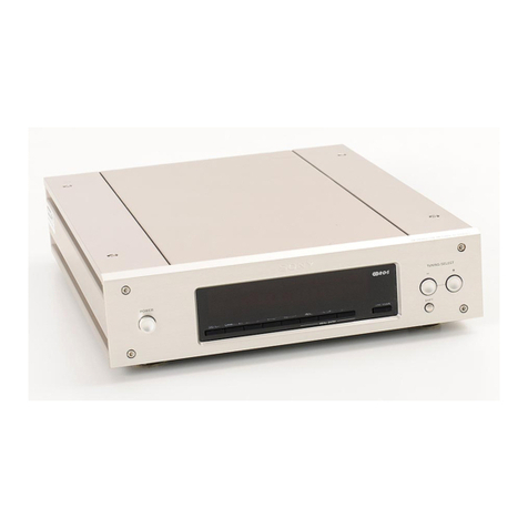
Sequerra 1 User manual


CONTENTS
President'sLetter
GuaranteeCertificate
Two
WarrantyRegistrationCertificates
CertificateofMeasuredPerformance
Operational
Instructions
InstallationInstructions1
Front
Illustration2
Immediate
Operation3
DescriptionofTunerDisplays.4
Back
PanelIllustration, 7
DescriptionofBackJackPanel8
DetailedDescriptionof
Scope
11
Graticule
andTraceDescriptions13
Simplified
TheoryofOperation20
Block
Diagram23
Back
JackPanel
Socket
24
Final
TestCheckList
Mounting
Template
RepackingInstructions
SparePartsList
SparePartsPacket
5174

THEBEQUERBACO..mc
71-07WOODSIDE
AVENUE
WOODSIDE.N.Y.11377
(212)
651-4018
Dear
Customer:
I
wouldliketo take
this
opportunitytopersonallythankyouforbecomingone
of
thediscerningIndividualstoowna Sequerra
Model
1 FM
Tuner.
Thisinstrument
representsa
state
oftheartachievementintheHiFidelityIndustry,andembodies
in
excess
of
25,000
hoursofengineering.
When
completed,your
Model
1 FM
Tuner
wasIndividuallymeasuredfora
number
ofperformancecharacteristics.Themeasurementsaredocumentedona signed
Certificate
ofPerformance,bearingtheserialnumberofyourindividual
Tuner.
Your
Model
1 iscoveredbytheSequerraFive
Year
Warrantyto
meet
thestandard
specifications.I wouldliketo callyourattentiontoa numberof
exceptions
tothe
plan:
1.The
Model
1
Tuner
mustbepurchasedonlyfroma FranchisedDealer.
2.Anyresale,orgiftofthe
Model
1,requiresthefactory'sacceptanceofthe
transferoftheunexpired
Warranty.
3.TheCompanyundernoconditionswouldhonora WarrantyIfit
does
not
meet
allofthecriteriasetforthintheWarrantyRegistrationCertificate.
Although
theWarrantyisin
effect
forfiveyears,designandmanufactureof
your
Tuner
Isaimedata usefullifeofat
least
tenyears.Shouldyour
Model
1 FM
Tuner
requireservicing,
please
contactonlyyourFranchisedDealer,orthefactory
directly,
asthecomplexityofdesignrendersitbeyondthemaintenancecapabilities
of
theuntrainedserviceman.
Our
Companyisdedicatedtothedevelopmentofextremelyhighquality
products,manufacturedinverylimitedquantities.Weanticipatethatourproducts
will
alwaysbeinshortsupply,thereforeweoffertoeverypurchaserofthe
Model
1
FM
Tuner,
a preferential
status
vls-a-vlspurchaseofanyofourfutureproducts,and
weanxiouslysolicityourInspectionofourfutureproducts.Aswithanysmall
engineeringbasedorganization,we
welcome
suggestions
andcriticismsfromour
customers,andhopeto enterintosucha dialoguewithyou.
We
feelyour
Tuner
willprovideyouwithyearsofsatisfyingperformanceand
lookforwardto servingyouagainInthefuture.
f
>\
Richard
Sequerra
President
5174

INSTALLATION
INSTRUCTIONS
IninstallingtheSequerraModel1 FMTuner,certainprecautionsmustbeobserved.Followthe
InstallationInstructionscarefully,andinsequence.Itisadvisedthatyoufamiliarizeyourselfthor-
oughlywiththepushbuttondisplaysandthebackjackpaneltoappreciatethecapabilitiesofthe
tuner.
Thefollowingpageswillimpartanin-depthunderstanding.Thepageentitled
Immediate
Oper-
ation
explainshowtoquicklyworkyourtuneronceitisproperlyinstalled,withoutthoroughly
understandingit.Buttoappreciatethefullsignificanceoftheperformanceofthetuner,andto
makeallowableadjustmentstoenhancethelisteningquality,a thoroughunderstandingofitsoper-
ationsisimperative.
Warning:
Pleasekeepinmindthatthewarrantydoesnotcoverdamagecausedby
misuse,mishandling,insufficientventilation,orexcessivelinevoltage.
Placement - Thetunershouldnotbeplacednearanysourceofheat.Allowa minimumoftwo
inchesclearanceabove,behind,andbelowthetunerforventilation.
Custom
Installation
— Ifyouareinstallingthetunerinanequipmentcabinet,orbehinda
panel,
usethemountingtemplate(nearbackofthismanual)tomaketherequiredholesandcut-
outs.
Antenna
— Choosingtheproperantennasystemisessentialinordertominimizemultipath
interference.Signalreflectionsfromsurroundingbuildings,towers,orhillscausemultipathinter-
ference.Thisphenomenon,similarto"ghosts"inTV,producesdistortionintheFMsignalsatthe
antenna.
NoFMtunercancompletelyeliminatemultipathinterference,thereforecarefulselection
of
anantennaisnecessaryinordertooptimizeperformanceofthesystem.ThebestFMreceptionis
obtainedwitha steerableorrotatableantenna.Thisholdstrueforeitheranindoororoutdooran-
tennausedinconjunctionwitha rotorsystem.A comprehensivediscussionofFMandFMsystem
problems(includingantennas)isavailablefromtheSequerraCompanyinbookletform.Theprice
of
$1.00covershandlingandmailing.
Output
— Connectthetunertothepre-ampusingthetuner'sOutputFixedjacksontheback
panel.
L & R standforleftandright.Besuretoconnectlefttoleft,andrighttoright,fromtuner
topre-amp.
Domestic
Units
— Makesurethatlocalpowerisnominally120voltsACat60Hzasmarkedon
thetuner'sbackpanel.
Export
Units
— Powertransformerisadjustedfora lineinputvoltageof220to240volts.A
properslowblowfusehasbeeninstalled.
Power
Line
— UnwindthepowercordandplugitintoanACwalloutlet.
5174
1

FRONT
ILLUSTRATION
For
Immediate
operation(afterproperlyfollowingInstallationInstructions)employpushbuttons
as
shown
by
FunctionArrows
In
thisIllustration.
5174 2

IMMEDIATEOPERATION
Toimmediatelyoperatethetuner(afteritisproperlyconnectedandpluggedin}withouta
fundamentalunderstandingofthevariouspushbuttonfunctions,simplydepressthelowestright-
handpushbuttonwhichbearstheSequerra"S".Thiswillturntheseton.Turntheknobtotunein
yourdesiredstation.Thestation'sfrequencyappearsonthedigitalreadoutdisplayabovetheword
Megahertz. Anovercapacityoftuningisprovidedwhichpermitsthesettobetunedfrom87.7MHz
through108.3MHz.The
Stereo
Pilot
willbeilluminatedifthetunedstationisbroadcastinga
stereoprogram.Itissuggestedthatthefollowingpushbuttonsbeemployed:
Display:
Tuning
Separa
tion:
Maximum
Dofby.Off
Muting:
Inter-Station
Mode
:A u
tomatic
5174

DESCRIPTIONOFTUNERDISPLAYS
Thetwoverticalrowsofsixpushbuttonseachoperatethefunctionsdescribedontheiradja-
centdisplaywindows.Thearrowswhenlit,pointingtothedisplays,willindicatewhichdisplaysare
functioning.Theupperfourpushbuttonsontheleftareoscilloscopefunctionselectors.Theyare
interdependent,anddepressinganyoneofthefourwillreleaseanyotheroneofthefourwhichwas
previouslydepressed.
Asimilarstructureexistswiththethreemutingpushbuttonsonthetoprightside.Theremain-
ingfivepushbuttonsareindividuallyindependentofanyother,andwhendepressedwillremainso
untilindividuallyreleasedbydepressingThemagain.
Thefollowingdescriptionscoverpushbuttonfunctions.A moredetailedanalysisoftheoscillo-
scope'stracesareexploredlater.
DISPLAY
Theupperpushbutton.Display:Panoramic, displaysallstationsthataretransmitting
1MHzaboveandbelowthetunedfrequency.Theverticalpipsofthescope'strace
representstationswhicharebroadcastinga signalabovetheambientinterstationnoiselevel,which
isthebaseline.Whentunedtoa particularfrequency,thestationyouarelisteningtowillbe
cen-
teredonthescope'sgraticule.
DISPLAY
Thesecondpushbuttonontheleft,
Display .-Tuning
isusedtoproperlytunetheset.
Forpropertuning,thetraceshouldbeadjustedfortheuppercenterofitspath.
DISPLAY
TLTvjtR
V1CTCJM Thethirdpushbutton,Display:Tuner
Vector,
displaystheaudiocomponentsonan
X-Ybasis.Thisvectorexhibitstheleftandrightstereochannelsalonga perpendic-
ularaxis.Itisusedincheckingtheseparationandphasecharacteristicsofstereoprogrammaterial.
Thewidertheangle,thegreatertheseparation.Thehigherthetrace,thestrongerthesignal.A
verticallineindicatesnoseparation(asa centrallypositionedannouncer,ormonophonictrans-
mission).
C*SPCAY
EXTVI
UHJM
Thefourthpushbutton.
Display:Ext.
Vector,
displaysseparationandphasecharac-
teristicsofanystereoorfour-channelprogramming.Tobefunctional,proper
con-
nectionshavetobemadetotheExternalVectorInputsectioninthebackpanel.Stereoprogram
materialisdisplayedidenticallytoDisplay:TunerVector.Four-channelprogrammaterialisdis-
playedon4-legsofan"X"shapedtrace,indicatingthecornersoffront,rear,left,right.Thesepara-
tion,
phase,andamplitudeofeachlegofquadprogrammingcanbeobserved.
SEPARATION
Thefifthpushbutton,Separation:
Maximum-Hi
Blend,
controlstheseparationofthe
highfrequenciesinstereobroadcasting.Itisusedtoeliminatesomenoiseunder
difficultlisteningconditions.OrdinarilyhaveitsettoMaximumforbestspatialanddirectional
definitionoflisteningmaterial.
5174
4

Whenencounteringexcessiveinterferenceorbackgroundnoise,switchtheSeparationtoHi
Blend.
Thispositionblendsthehighfrequenciesoftheleftandrightchannelstogetherprovidinga
goodcompromise,betweenmoderateseparationandmoderatesuppression,ofout-of-phasenoise
anddistortion.Thispermitsyoutomaintainfullfrequencyresponse,differingfromconventional
noisefilterswhicheliminatenoisebyreducinghighfrequencyresponse.Note:IftheHiBlend
positiondoesnotsatisfactorilyreducestereonoise,switchingtheModedisplayfunctionfromAuto-
matictoMono(fourthpushbuttononright)completelyeliminatesallstereonoise,buttheprogram
willbereceivedmonophonically.
Thebottompushbuttonontheleft,Dolby.Off-On, interposesorremovesa Dolby
TypeB decoderintheoutputaudiolines,-affordingyouthebenefitsoftheDolby
noisereductionsystemwhenthestationistransmittingDolby.
Theupperthreepushbuttonsontherightareformutingfunctions.Theyareinterrelatedand
depressinganyonecancelsouttheothertwo.Themutinglevelissetbyanadjustmentontheback
jackpaneloftheset(refertoBackPanelMutingInstructions).
objectionable(withthehighperformanceoftheSequerraTunerthisnoiseappearsaccentuated),it
isusefulingivingyoua truerunderstandingofwhatisreallyhappeningthroughouttheentire
broadcastband.Itpermitsyoutohearbroadcasts,witha veryweaksignalstrength,thatare
beneaththepresetmutinglevel.
MUTING
MUTING
•NTER
BllOfO
Thesecondpushbuttondown.Muting:Inter-Station,mutesallundesirednoise
(beneaththepresetmutinglevel)whiletuningbetweenstations.
Thethirdpushbutton.Muting:Inter-Stereo.willmutenotonlyinter-stationnoise
butalsomonophonicbroadcasts,allowingyoutoreceiveonlystereobroadcasts.
Thereisanothermutingsystemdesignedintothetunerwhichisnon-adjustable.(TheMuting
LeveladjustmentisontheBackJackPanel).Ithastodowithoff-centertuningnoise.Tobest
understandit,considertheDisplay:Tuningpattern.Whena stationisproperlytunedthetraceison
thecenterline.Asthetraceapproachesandgoesdownthesidesofthetuningpattern(offcenter
frequency)itisautomaticallymuted.ThismutingcircuitoperateswheneitherInter-Stationor
Inter-Stereomutingisincorporated.Itisby-passedwhenMuting:Offisengaged.
Thefourthpushbuttonontheright.
Mode:
Automatic-Mono, intheautomaticposi-
tion,
automaticallysenseswhetherthereceivedsignalisstereoormono,andchan-
nelsthesignalthroughthepropercircuitry.ConsequentlyitisusuallykeptintheAutomaticposi-
tion.
TheStereoPilotwilllightwhena stereoprogramisbeingreceived.Whena monoprogramis
beingreceivedthesetisdesignedtobypassthemultiplexdecodingcircuitry,thuseliminatingany
possiblestereonoise.WiththeModepushbuttondepressedtoMono,itwillreceivestereoprograms
monophonically.Thisisusefulineliminatingallstereonoiseswhenstereoprogrammingisbeing
AUTOMATIC
MODE
5174
b
OOLBV
Depressingthetoppushbutton,
Muting.Off,
cancelsoutallmutingfunctions.Inthis
modeallinter-stationnoiseisheard.Althoughmostpeoplefindinter-stationnoise

receivedunderdifficultconditions,andtheSeparation:HiBlendpushbuttondoesnotsufficiently
eliminateundesirablenoise.Ofcourse,inthismode,theprogramwillbeheardinmono.
ItisalsosuggestedtohavetheModeinMonowhenlisteningtoa monophonicprogram,to
eliminateanypossibilityofanunwantedsignaltriggeringtheStereoPilot.Thiswoulddirectthe
programmedmaterialthroughthemultiplexdecoder,andconsequentlypickupanyconcommitant
stereonoise.Ifthisoccurs,theStereoPilotwillflickon.
PANEL
DIM
The Panel:Normal-Dim, pushbuttonmerelychangestheintensityoftheillumination
of
thedisplayscreensandoscilloscope.
PDWEP
The
Power:
On pushbuttonswitchesthetuneronandoff.Itismarkedwiththe
Sequerra"S",theonlyidentificationonthefrontoftheset.whichservesforeasily
locatingthepowerbuttonwhenthesetisinits"blackout"position.IntheOnpositionitlightsall
functionaldisplays.
5174
6

BACKJACK
PANEL
FOCUSINTENSITY-*A0]USTFORVERY
DIM
SPOTONEXTVECTOR
POSITIONWITHNOSIGNAL
SCOPE
VERT.
HOR.
CENTERING
25MSEC.
DOLBY
MUTING
LEVEL
DETECTOR
OUTPUT
PANORAMIC
SWEEP
WIDTHCENTER
ACCESSORY
FUSE 105-135VAC
50-60
Hz
SERIALNUMBER
L
OUTPUT
R
FIXED
LEVEL
OUTPUT
EXT.VECTOR
INPUT
FRONT
R
LEVEL
REAR
ANTENNA
CONNECTION
TERMINALS
300
n
75
n
Connect
antenna
leads
toappropriateterminals(matchImpedances) 7
5174

DESCRIPTIONOFBACKJACKPANEL
ThebackJackPanelhasfourinputs,fiveoutputs,anaccessorysocket,scopeandpanadjust-
ments,a Dolbyconverter,a fuse,thelinecord,andtheserialnumber.Followingisa descriptionof
theirproperuse.
Fuse
— For
U.S.A.
a l-amp,slow-blow,standard3AGcartridgetypefuseisused.Fornon-
domesticuse,theproperfuseforthecountryofusehasbeeninstalled.
Power
Line
Cord
- PlugonlyintoACoutlet.In
U.S.A.
115VAC50-60Hz.Properoperation
willbehadfrom105-135V.Europeantunersareadjustedfor220VAC.50Hz(refertoExport
UnitsinInstallationInstructionssection).
Whentakingthetunerfromonecountrytoanother,takeitonlytoanauthorizeddealerinthe
countryofuseforproperconversion.Servicingbyuserorunauthorizedpersonnelwillvoidwar-
ranty
Output
Fixed
- Usethisoutputtoplugintostereopreamplifier.Delivers1 voltRMSfor
100%
modulationfromaninternalimpedanceof600ohmsintoanopencircuitorhighimpedance
load.
Candeliver% voltinto600ohmexternalload.CanDriveasmuchas100feetof33picofarad
cableoneachoutputlegwithoutcausinganydegenerationofsignal.
Output
Level
— Thisoutputconsistsofa 5,000ohmpotconnectedacrosstheoutputofthe
FixedOutput.Ithasa varyinginternalimpedancethatcannotexceed2800ohms.Itcanbeusedto
driveshortstandardcablesintohighimpedanceinputs.
External
Vector
Input
— Inputforfour-channelsignalsourceforscopedisplaythroughthe
tuner'sfour-channelmatrixcircuit.DepresstheDisplay:ExternalVectorpushbutton.Alsomaybe
usedtomonitorexternalstereosources.UseFront,L & R inputs.
Scope
- AllSequerratunersareproperlyadjustedbeforeleavingthefactory.Ifforanyreason
thescope'straceneedsadjusting,followtheproperprocedure:
1.
Removeallinputs.
2.
WithsmallscrewdriversettheScopeIntensityadjustmenttofullcounterclockwise
position.
3.Setscope'sFocus,Vertical,andHorizontaladjustmentstocenterposition.
4Switchpoweron.Allowa minimumof1 minutefortubetocompletelywarmup.Itis
bettertowail15minutestoallowthetunertostabilizeatfulloperatingtemperature,
thusavoidinganypossibledrifteffect.
5.DepresstheDisplay:ExternalVectorpushbutton.
5174
B

6.SlowlyturnIntensityAdjustmentClockwiseuntila verydim(barelyvisible)trace
appearsonthescope'sscreen.Itisimportanttokeepthistraceextremelydim.Auto-
maticbrighteningcircuitrywilladjusttheintensityasrequiredduringperformance.A
brightspotwillcauseburn-inandshortentheoscilloscopetube'slife.Suchusewillvoid
thewarranty.NowadjusttheFocuscontroluntilthescope'stracebecomesthesmallest
possibledot.AgainadjusttheIntensitycontrolforthedimmestpossibledot.The
VerticalandHorizontalcontrolsareusedtobringthedotintotheexactcerterofthe
scope.Toproperlycenterthedot,observethetubeexactlydead-on-centerfromthe
fronttoavoidanyparallex.Usethecenterverticallinewithitscentercrossmarkto
locatetheexactcenter.
Muting
Level
— Thisadjustmentisusedtotuneoutallsignalshavingnoiselevelwhichis
unacceptabletoyou.
1.
DepresstheMuting:Offpushbutton.
2.
Tuneina stationwhichyouconsidertobeonthethresholdofhavinganunacceptable
noiselevel.
3.DepresstheMuting:Inter-Stationpushbutton.
4.
AdjusttheMutingLevelcontroltothepointwherethatstationjustmutesout.
Nowanystationwitha noiselevelequalto,ormorethanthestationjustusedwillbemuted
outasyoutunethroughtheFMband.ThismutinglevelappliestoboththeMuting:Inter-Station,
andMuting:Inter-Stereopushbuttons.ThepotentiometerusedfortheMutingLevelcontrolhasa
rangeof3 microvoltsto30microvolts.
Panoramic
Sweep
— Theelectronicsforthepanoramicdisplayfunctionisoptionalandisnot
includedinallsets.Again,rememberthatalltunersareadjustedbeforeleavingthefactory.But,in
theeventthepanoramictraceneedsadjustment,followtheseprocedures.Thistaskcanbemade
simplerwitha properunderstandingofwhat'sonthescreen.Theimportantthingtounderstandis:
1.
Theverticallinesonthegraticulearedesignedtobe400Hzapart.
2.
TheFCCfrequencyassignmentstoalternate(primary)stationsare400Hzapart.This
spacestheadjacentstationsmidway(200Hz)betweenthealternates.
Inrelativestrongsignalareas,itmaybeadvantageoustoremovetheantennaleadsandreplace
themwitha smallpieceofwire.Althoughthepipswillnotbeasstrong,theymaybemoreeasily
adjustable.
To
AdjustCentering:
1.
DepresstheDisplay:Panoramicpushbuttonandtunefora primarystationbycenteringa
largepip.
2.
NowdepresstheDisplay:Tuningpushbuttonformoreaccuratecentertuningandchecking
thestationfrequencyonthedigitalreadout.
9
5174

3.NowdepresstheDisplay:Panoramicbuttonagain.Donottouchthetuningknob,andifthe
station'spipisoffcenter,centerthepipbyadjustingthePanoramicSweepCentercontrol.
ToAdjustWidth:
1.
DepresstheDisplay:Panoramicpushbutton.
2.
Selecta portionofthebroadcastbandwheretheprimaryalternatestationsarebroad-
casting.
3.Identifythepipsbyusingthedigitalreadout(switchmomentarilytoDisplay:Tuningfor
moreaccuratetuning).
4.
ThenbyusingtheWidthadiustmentcontrol,alignthepipsoftheprimaryalternatestations
withtheverticallinesonthegraticule.
TheWidthadjustmentmaymovethepipsoffcenter,inwhichcasegobackandadjustthe
centering.
Youmayhavetogobackandforthseveraltimesbeforeattainingoptimumalignment.
Thefinaladjustmentmaynotfallexactlyonthelines,asthescopedisplaysareapproximateand
notdesignedforhairlineperfection.A highlyusablecompromiseiseasilyachieved.
25 Microsecond
Dolby
- ThepresentU.S.A.Dolbystandardisfor75microsecondde-
emphasis.Europeansetsaredeliveredtooperateat50microsecondde-emphasis,whichisthe
Europeanstandard.Conversionfromonestandardtotheotherisa simplematter,butshouldbe
doneonlybya FranchisedDealer.
Presentlyinthe
U.S.A.
thereareconsiderationsbytheFCCofpermittingand/orstandardizing
on25microsecondoperation.Ininstancesof25microsecondbroadcastingallthatisrequiredfor
thetunertobeproperlyconvertedistoinserta shortingplugintothe25MicrosecondDolbyjack.
Detector
Output
— Thisoutputsuppliesa signal,beforede-emphasizing,directlyfromthe
outputoftheFMdetectorpriortomultiplexdecoding.Thisoutputhasapplicationtofour-channel
demodulation,broadcasttesting,andotherspecialpurposes.
Accessory — Whennotinuse,theshortingplugsuppliedwiththetunermustbeproperlyin
thesocket.Ifitislooseorabsent,thedigitalreadoutwillreadeither189.3MHzorbelow88.0
MHz,andturningthetuningknobwillnoteffectthesereadings.
TheAccessoryjackisusedtointerfacethetunerwithvariousaccessories,i.e.theoptional
remotepushbuttontuningassembly.
5174
10

DETAILEDDESCRIPTIONOFSCOPE
Athoroughunderstandingoftheinformationshownbytheoscilloscope'stracewillgivean
appreciationofwhalisbeingbroadcastplusthequalityofthebroadcast.Thispresentsanoppor-
tunitytomakeallowableadjustments,withthetunerandantenna,toachievethebestpossible
receptionofreceivableprograms.Allscopemeasurementsandtraceinformationareapproximate.
Theyareusedtoestablishreferencesandarenotdesignedforhairlineaccuracy.
Thecathoderaydisplaytuberequiresgreaterwarm-uptime(about30seconds)thanthedis-
playsbeforethetracebecomesvisible.
Theoscilloscopedisplaydimsautomaticallywheneverthetracereducestoa "dot"(atlowor
noaudiosignallevels).Thisautomaticdimmingactionextendsthelifeofthecathoderaytubeand
reducesthepossibilityofaccidentlyburningthescreenphosphors.
Panoramic
— Inthismodethescdpedisplaysallstationsbroadcastingwithina 2 MHzspec-
trum.
(1MHzeachsideofthetunedfrequency).Theheightofthepipsindicatetherelativesignal
strengthofthestations.Thenoticeablemotionofthepipsistheresultofthematerialbeingbroad-
castedplusmultipath.Thepanresponseisflatatthecenteralthoughnotacrosstheentire2 MHz.
Thiswillcausesomeslightdiminishingoftheheightofthepipsastheyaretunedacrosstheband
awayfromcenterfrequency.Theheightofthepipsindicatetherelativesignalstrengthofthe
stationsandcorrespondstotheapproximateheightofthetraceofthetuningdisplay(secondpush-
button).
Thisisjustanapproximateheightmatchasthecenterverticallineonthepandisplayhasa
dynamicrangeofapproximately100dB.Thisistheresultofsomeslightcompressionatthetopand
displacementatthebottom.Theverticalcenterlineonthegraticuledelineatesthecenterfre-
quency.Thetwoverticallinesoneithersideofthecenterlinearespacedatintervalsof400kHz.
ThisspacingcorrespondstotheFCCspacingofalternatestationsonthebandwidth.Adjacent
stationsfallmidwaybetweenthealternatesat200kHzspacings,andwhenthesetistunedwitha
primarystationonthecenterline,thealternatestationswillbeontheverticallines,whilethead-
jacentstationswillfallbetweenthelines.
Athree-pointedtracerepresentsa stationwithanSCAsubcarrier.SomeFMstationssimul-
taneouslybroadcasta SubsidiaryCommunicationsAuthority(SCA)signalonthesamecarrierfre-
quencyastheirregularbroadcast.SCAbroadcastsareprivatelysoldtocommercialuserssuchas
restaurants,offices,stores,etc.,andcontainnocommercialadvertising.
NOTE: Allspectrumanalyzersproducea varyingnumberofambiguousanderroneousdisplays.
ThePanoramicDisplayintheModel1 Tunerisnoexception.Thetypesoferroneousdisplaysthat
youmayexpectarelistedasfollows:
1.
Image
Responses: Allstationshavinga signalstrengthofgreaterthan5000microvoltswill
produceanimageresponseinthedisplayprecisely4.8MHzabovethestation.
2.
Spurious
Responses: Theseresponses,inthistuner,areattributedmainlytothedynamicrange
limitationsofthesystem.Thedynamicrangeupperthresholdis100,000microvolts.Signal
inputgreaterthanthatproducessignificantdisplacementofthebaselineaswellasa seriesof
sidebandmodulationproducts.
11
5174

3.
Crossmodulalionproductsduetotheoutofbandsignalsi.e..excessivelystrongtelevision
signalsbelowtheFMbandandexcessivelystrongaircraftsignalsabovetheFMbandmay
producespuriousresponses.
4.
ClandestineFMtransmittersi.e.,buggingdevices,radiationfromotherFMtuners,andother
sourcesofelectromagneticradiationwithinthebandwillbereadasresponsesinthePanoramic
Display.
Tuning
— Theoscilloscopetracefollowsanapproximatetrapezoid.Spinningthetuningknob
fastwillgiveanideaofthebandpasspattern.Signalstrengthisindicatedbytherelativeheightof
thetraceabovetheinter-stationnoiselevel(thelowerandheavierhorizontalpathofthetrace).The
centergraticulelinedisplaysa dynamicrangeofapproximately110dB.Itisdividedintodecades.
Thesecalloutsarenotmeanttobeexactbutareonlyapproximate.They'regivenforrelativedis-
cernmentofsignalstrength.
Modulation(orcarrierdeviation)isdisplayedbytheinstantaneoushorizontalexpansionand
contractionofthetracewhentunedattheuppercenter.Loudpassagesareindicatedbywide
traces,whilesofterpassagesareseenasproportionallyshortertraces.Over-modulationbythetrans-
mitterisdisplayedasanexcessivelywidetraceextendingbeyondthetwoverticallinesoneither
sideofthecenterline.Theseverticallinesrepresenttheinstantaneouspeakdeviationof75kHz
eithersideofthecenterline.
Weakdistantstationscanbeseenonthescopealthoughtheymaybebelowthetuner'sset
mutingthreshold.Adjustingantennadirectionwillfrequentlyincreasesignalstrengthsufficientlyto
pullthesignaloutoftheinter-stationnoiselevelandgivegoodreception.Inextremecases,a very
weaksignalcanbemadeaudiblebysettingMutingtoOff.
AstationbroadcastinganSCAsidebandcanalsobeseenwiththeTuningDisplay.Itis
detectedbyaninwardreachofthetracewhenthetraceisattheupperportionofeithersideofthe
tracepattern.
Adjusting
Antenna
Direction
For
Minimum
Multipath
— Thetuningdisplayservestheim-
portantfunctionbyshowingwhentheantennaispointedtobestpossibledirectiontominimize
multipath.Multipathinterference,similartoa "ghost"inTVpictures,producesdistortioninthe
FMsignalsatthereceivingantenna.Thisresultsina distortedsound.Tominimizemultipathinter-
ference,andobtainthebestreceptionfromeachstation,adjusttheantennatothedirectionwhich
resultsinthesmoothestandmosthorizontaltrace.Thisdirectionfrequentlymaynotbethesame
asthedirectionforthestrongestsignal(maximumverticaldeflection).
5174
12

PANORAMIC
GRATICULEDESCIRPTIONS
'400kHzSpacings
2MHz
FrequencySpectrum
IdealDynamicRange
-120dB,lV
T00dB,100,000uV
•80dB,10,000uV
60dB1,000uV
40dB,100uV
20dB,10uV
100dB
ActualDynamicRangedueto
compressionattopanddis-
placementatbottom
517
00
13

PANORAMIC
DESCRIPTION
OFPIPS
A.
Tuned
instationon
centerfrequency.
B.
Alternatestation400
kHz
offcenterfrequency
C.
Alternatestation800
kHz
offcenterfrequency.
Note:3-pointedpipindicates
stationsimultaneously
broad-
casting
SCA.
D.
Adjacentstation200kHz
off
centerfrequency.
Samebroadcastreceivedby2 differentantenna
systems.
A.
Rabbit
ear
FM
antenna
B.
Outdoorroofantenna
(note
overload).
This
was
close
line-of-sightdeveloping0.3Vinputto tuner.
2"
Stationswithsamesignal
strength
A.
Monaural
B.
Stereophonic
C.
Bendattopofpip
Indicates
stereo
pilot.
5174
14

TUNING
5174
75kHzSpacings
Typical
(complete
cycle)
Trace
Pattern
Amplitute(SignalStrength)
Noise
Level
Noise
Density
Graticule
Description
Trace
DescrlDtlon
For
DynamicRangeseePanoramicGraticuleDescription
15

TUNING
TRACE
DESCRIPTIONS
Soft
Passages
Loud
Passages
(Full
Modulation)
Over/modulation
by
broadcaster
(causes
distortion)
Station
not
properlytuned
Off-Tuned
trace
(ShowingSCA
sub-
carrier)
Weak
Station
5174
StationwithLowAmplitude Stationwith
High
Amplitude
16

TUNING
MULTIPATH
Ideal
Trace
(NoMultipath)
Multipath
progressivelyworse(AtrhoughE).Thelong
gentle
curveofA ispreferableto B,etc.Intuningto
eliminateorminimizemultipath,rotateyourantenna
togetthe
smoothest
trace.
This
willbeyour
best
listeningposition,evenIfithas
less
amplitudethan
in
otherpositions.
Very
severe
multipath
(partial
cancelationofsignal)
5174
17
Table of contents

