GS Teletech CoverCell25KN Quick start guide

FCC ID : U88-COVERCELL25KN
HCT CO., LTD.
SAN 136-1, AMI-RI, BUBAL-EUP, ICHEON-SI, KYOUNGKI-DO, 467-701, KOREA
TEL:+82 31 639 8517 FAX:+82 31 639 8525 www.hct.co.kr
Report No. : HCTR1006FR16 1/1
ATTACHMENT E.
- USER MANUAL -

CoverCell25KN
Technician's Operational Manual
Ver. 0.1
Version 0.1 ؼApril 2010
© 2010, GS Teletech, Inc. 2
Contents of Box
Contents Picture Quantity Contents Picture Quantity
Repeater 1EA Ground Cable
6.6ft (2m) 1EA
Mounting Bracket 1EA Ground Sems Screw
M4 x 8mm 4EA
Installation Guide CD 1EA Bracket Sems Screw
M6 x 16mm 4EA
Ethernet Cable
6.6ft (2m) 1EA Lag Screw
1/2" x 2" 4EA
Power Cord
6.6ft (2m) 1EA Anchor Bolt Set
1/2" x 2" 4EA
Registration Form 1EA

Version 0.1 ؼApril 2010
© 2010, GS Teletech, Inc. 3
This publication provides instruction for installing Verizon 24dBm Dual Band Inbuilding RF repeater.
The images for the User Interface in this publication may vary from the repeater’s depending on its
S/W Version.
Copyright
© 2010, GS Teletech, Inc.
All Rights Reserved
Printed in Republic of Korea
Revision History
Date Version Changes
04/2010 0.1 Draft
Certification
UL/FCC: This equipment complies with UL and FCC
Version 0.1 ؼApril 2010
© 2010, GS Teletech, Inc. 4
Warnings and Hazards
WARNING! ELECTRIC SHOCK
Opening the BDA (bi-directional amplifier) could result in electric shock and may cause severe injury.
WARNING! EXPOSURE TO RF
Working with the repeater while in operation, may expose the technician to RF electromagnetic fields
that exceed FCC rules for human exposure. Visit the FCC website at http://www.fcc.gov/oet/rfsafety
to learn more about the effects of exposure to RF electromagnetic fields.
WARNING! DAMAGE TO EQUIPMENT
Operating the BDA with antennas in very close proximity facing each other could lead to severe damage to the repeater.
RF EXPOSURE & ANTENNA PLACEMENT
Actual separation distance is determined upon gain of antenna used.
Please maintain a minimum safe distance of at least 8 inch while operating near the donor and the server antennas.
Also, the donor antenna needs to be mounted outdoors on a permanent structure.
WARRANTY
Unauthorized opening or tampering the BDA will void all warranties.
One-year Warranty will start when the ownership of CoverCell25KN Repeater is transferring.
!CAUTION: REPEATER SHOULD BE INSTALLED AS CLOSE AS POSSIBLE TO POWER SOURCE.
!CAUTION: THIS REPEATER IS FOR INDOOR USE ONLY AND SHOULD BE LOCATED INSIDE OF BUILDING.
!CAUTION: RISK OF EXPLOSION IF BATTERY ON CONTROLLER BOARD IS REPLACED WITH AN INCORRECT TYPE.

Version 0.1 ؼApril 2010
© 2010, GS Teletech, Inc. 5
System Specification
Item Downlink Uplink Remark
Cellular
Frequency
(MHz)
A1 869 ~ 880 824 ~ 835
A2 890 ~ 891.5 845 ~ 846.5
B1 880 ~ 890 835 ~ 845
B2 891.5 ~ 894 846.5 ~ 849
PCS Frequency (MHz) 1930 ~ 1990 1850 ~ 1910
Sub Band Filtering A1+A2 or B1+B2 or A1+B1+A2+B2
5, 10, 15, 20MHz BW (tunable)
Gain Cellular 80dB 80dB
PCS 80dB 80dB
Flatness 5dB peak to peak Channel power
Input Range Cellular -56dBm ~ -86dBm Max -56dBm
PCS -56dBm ~ -86dBm Max -56dBm
Output Power Cellular 24dBm 24dBm EIRP
PCS 24dBm 24dBm EIRP
AGC
Range
Cellular 30dB
PCS 30dB
Roll off Cellular ≥45dBc@±2MHz
≥30dBc @±0.25MHz (B1+B2 Inside Edge)
PCS ≥30dBc @±1.5MHz
Group Delay ≤ 6μs
Single &
2-tone
Cellular ≤Not to exceed maximum output power@-30dBm
PCS ≤Not to exceed maximum output power@-40dBm
Noise Figure ≤ 7dB
Input Inter-modulation ≤ 10dB
Adjacent
Channel
Power
Cellular ≥ 45dBc @ 750kHz
≥ 45dBc @ 1.98MHz
PCS ≥ 45dBc @ 885kHz
≥ 45dBc @ 1.98MHz
Radiated Spurious Emissions ≤ -13dBm
Frequency Error ± 300Hz @cellular, ± 150Hz @PCS
Signal Quality Rho >0.98
* type of modulation : F9W
Version 0.1 ؼApril 2010
© 2010, GS Teletech, Inc. 6
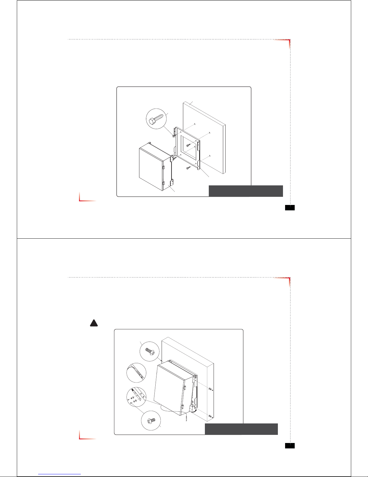
Mounting Repeater
Masonry Wall
1. Using a pencil, mark the location of each of the mounting bracket's four mounting holes on the wall.
2. Drill holes in the wall at the locations marked in step 1.
3. Set the anchors in the wall using a hammer.
4. Locate the four mounting bolts and place a lock washer and flat washer on each bolt.
5. Place the mounting bracket over the four holes with anchors, making sure that the washers are on the
repeater side of the mounting bracket. Tighten bolts until secure.
Anchor Bolt Set
1/2" x 2"
RF Repeater
Masonry Wall
Mounting Bracket
<Figure 1> Mounting the Repeater
on a Masonry Wall

Version 0.1 ؼApril 2010
© 2010, GS Teletech, Inc. 7
Mounting Repeater
Wood-Framed Wall
1. It is recommended to first attach a sheet of plywood to the wall. The sheet of plywood should be anchored to the studs
in the wall.
2. Using a pencil, mark the location for each of the mounting bracket's four mounting holes on the plywood.
3. Place the mounting bracket over the four lag screws heads.
4. Thread a lag screw at the positions marked in step 2.
<Figure 2> Mounting the Repeater
on a Wood-Framed Wall
Lag Screw
1/2" x 2"
RF Repeater
Wood-Framed Wall
Mounting Bracket
Version 0.1 ؼApril 2010
© 2010, GS Teletech, Inc. 8
Bracket Sems Screw
M6 x 16 mm
Ground Sems Screw
M4 x 8 mm
Ground lug detail drawing
To approved ground source
!
<Figure 3> Hanging and Grounding
the Repeater
Hanging and Grounding
1. Hang the Repeater from the mounting bracket.
2. Locate the four Bracket Sems Screws with installed washers. Tighten bolts until secure.
3. Locate the ground lug on the underside(or side) of the repeater.
4. Crimp the ground cable to the ground lug.
5. Route the free end of the ground cable to an approved(per local code or practice) ground source.
CAUTION
Ground cable must be properly grounded to provide both EMI and voltage surge protection for the repeater.

Version 0.1 ؼApril 2010
© 2010, GS Teletech, Inc. 9
Position Antenna
• Customer specifications should be followed for positioning the antennas properly.
<Figure 4> An installer is directing Donor Antenna to
nearby BTS to receive strong input signal.
Version 0.1 ؼApril 2010
© 2010, GS Teletech, Inc. 10
Cable Connections
• Connect Donor and Coverage Antenna
!CAUTION
Do not connect or disconnect cable from ANT port when power is ON
<Figure 5> ANT Ports
<Figure 6> DONOR ANT Port Connection <Figure 7> Covergare ANT Port Connection
jv}lyhnlGhu{kvuvyGhu{

Version 0.1 ؼApril 2010
© 2010, GS Teletech, Inc. 11
Connecting Power Cable and LED Light Verification
• Connect Power Cable
• When turning on the repeater, AGS (Auto Gain Setup) is automatically activated, which shows LED indicators are
turned on one by one.
• After all the LEDs are on, AGS is complete.
• Please verify that all the LEDs are indicating proper input and output levels.
<Figure 9> AC Power Port Connection <Figure 10> Verication of LED Lights
Version 0.1 ؼApril 2010
© 2010, GS Teletech, Inc. 12
LED Indicators
RUN LED : Green light ON
ALARM LED : Yellow light is alarm status
SHUT DOWN LED : Yellow light is shutdown status
<Figure 11> Front LED Display

Version 0.1 ؼApril 2010
© 2010, GS Teletech, Inc. 13
Input Power Signal
• Please note the number of LED bars indicates the RSSI signal strength level at the Donor ANT port.
The tables below indicate the levels.
Less than -85dBm LED 1bar
-84dBm ~ -67dBm LED 2 bars
-66dBm ~ -49dBm LED 3 bars
-48dBm ~ -31dBm LED 4 bars
More than -30dBm LED 5 bars
Common
Version 0.1 ؼApril 2010
© 2010, GS Teletech, Inc. 14
Output Power Signal
• Please note the number of LED bars indicates the downlink signal strength level at the Server ANT port.
The tables below indicate the levels.
Less than +5dBm LED 1bar
+6dBm ~ +10dBm LED 2 bars
+11dBm ~ +15dBm LED 3 bars
+16dBm ~ +20dBm LED 4 bars
More than +21dBm LED 5 bars
Cellular
Less than +5dBm LED 1bar
+6dBm ~ +10dBm LED 2 bars
+11dBm ~ +15dBm LED 3 bars
+16dBm ~ +20dBm LED 4 bars
More than +21dBm LED 5 bars
PCS

Version 0.1 ؼApril 2010
© 2010, GS Teletech, Inc. 15
Web UI
• Before connecting to repeater, disable wireless networking functions and remove wireless broadband card.
• Connect Ethernet Crossover cable from repeater LAN port to laptop.
<Figure 12> LAN Port Display
Version 0.1 ؼApril 2010
© 2010, GS Teletech, Inc. 16
Connecting to Web UI
1. Start-> Control Panel-> Network and Internet Connections
!CAUTION
Disable wireless connections and remove wireless broadband card.

Version 0.1 ؼApril 2010
© 2010, GS Teletech, Inc. 17
Connecting to Web UI
2. Right click Local Area Connections and choose Properties
- If your laptop is displaying multiple LAN’s, verify which one is used for repeater connection.
3. Click Internet Protocol (TCP/IP) on General Tab and click Properties
Version 0.1 ؼApril 2010
© 2010, GS Teletech, Inc. 18
On General Tab
4. Choose “Obtain IP address automatically”
5. Choose “Obtain DNS server address
automatically”
6 . Click “OK” to close Properties
7. Click “OK” to close Properties

Version 0.1 ؼApril 2010
© 2010, GS Teletech, Inc. 19
Connecting to Web UI
8. Right click Local Area Connections and choose Status
Version 0.1 ؼApril 2010
© 2010, GS Teletech, Inc. 20
Verify Assigned IP Address
9. Click on “Support” tab.
10. Verify assigned Default Gateway at local connection. (If IP address is not assigned, please click repair.)
11. Close all windows when finished.
Repeater's IP Adress

Version 0.1 ؼApril 2010
© 2010, GS Teletech, Inc. 21
Internet Explorer Option Settings
• Proceed step by step as indicated in the following slides to delete all temporary internet files and records.
1. Open Internet Explorer -> Tools -> Internet Options
Version 0.1 ؼApril 2010
© 2010, GS Teletech, Inc. 22
Browser History Options
On the “General“ tab, in the “Temporary Internet files” section:
2. Click "Delete Cookies...“
3. Click "Delete Files...“
4. Click “Apply”
5. Click “OK”

Version 0.1 ؼApril 2010
© 2010, GS Teletech, Inc. 23
Login Screen
Enter Default Gateway’s IP address into address bar as previously described, you
will be redirected to Login. Default User Name is ‘admin’, and default Password is
‘admin’. You may need to change password as described in the User Management
section. Repeater Location and Contact Information will initially be blank, you can
input Repeater Location and Contact Information as described in the Setup Wizard
section.
172.16.6.81
admin
admin
Version 0.1 ؼApril 2010
© 2010, GS Teletech, Inc. 24
List Menu
• After you log in, you can see various menu page links related to the equipment.

Version 0.1 ؼApril 2010
© 2010, GS Teletech, Inc. 25
Status Page
• Default D/L and U/L are set at minimum Gain.
• The default values in various fields will differ with different models of Covercell 25KN Repeaters.
• In order to view other pages, you can click the desired menu on the top-left corner of all pages.
• Changes can be made on the Status Page. This page is for checking the repeater’s conditions and settings.
Version 0.1 ؼApril 2010
© 2010, GS Teletech, Inc. 26
Status Page
• When an alarm goes off, the color of Status turns red.

Version 0.1 ؼApril 2010
© 2010, GS Teletech, Inc. 27
Communications Configuration
• Click on the Communications Configuration link.
Version 0.1 ؼApril 2010
© 2010, GS Teletech, Inc. 28
RF Configuration
• Click the RF Configuration link.
• This menu is where installer will actually configure the Repeater.
• You can change various RF values of the equipment on this page.

Version 0.1 ؼApril 2010
© 2010, GS Teletech, Inc. 29
RF Configuration
• In case that screen resolution is 1024 x 768, you may need to use scroll bars to view all.
•Changes will not take effect until you click “Apply” button.
•The default values in various fields will differ with different models of Covercell 25KN Repeaters.
Version 0.1 ؼApril 2010
© 2010, GS Teletech, Inc. 30
Automatic Setup Using AGS Function
•Set AGS Control to ‘ON’ and click Apply

Version 0.1 ؼApril 2010
© 2010, GS Teletech, Inc. 31
Automatic Setup Using AGS Function
•The screen shown below will be displayed while AGS is initializing.
• After AGS is completed normally, click “Click Result”. The equipment will set AGC, Gain Balance
and HPA “ON”, and then provide normal service. If automatic setup works you will see the Status page. (ALC “Off”)
Version 0.1 ؼApril 2010
© 2010, GS Teletech, Inc. 32
Alarm Configuration
• Click Alarm Configuration link.
• In case that Report Alarms is OFF, all alarms will be disabled. In case that Report Alarm is ON,
you can enable and disable individual alarms.

Version 0.1 ؼApril 2010
© 2010, GS Teletech, Inc. 33
Alarm Configuration
•
In case that screen resolution is 1024 x 768, you may need to use scroll bars to view all.
Changes will not be made effective until you click “Apply” button.
Version 0.1 ؼApril 2010
© 2010, GS Teletech, Inc. 34
User Management
•
Click on the User Management link.
•
On this page you can create and delete users, change passwords, and assign authorities to individual users.
•
Read/Write Authority means that the user can change various values.
•
Super User is very similar to an Administrator account.
!CAUTION
DO NOT DELETE 'admin'

Version 0.1 ؼApril 2010
© 2010, GS Teletech, Inc. 35
Alarm Logs
• Click on the Alarm Logs link.
• You can see Alarm Logs regarding Web UI operation. Alarm Logs will maintain a history of up to 100 operations.
Version 0.1 ؼApril 2010
© 2010, GS Teletech, Inc. 36
Logs
• Click on the Alarm Logs link.
• You can see Alarm Logs regarding Web UI operation. Logs will maintain a history of up to 30 operations.

Version 0.1 ؼApril 2010
© 2010, GS Teletech, Inc. 37
Troubleshooting Guide
• Click on the Troubleshooting link.
• You can refer to this page for a general troubleshooting guide.
• In case that screen resolution is 1024 x 768, you may need to use scroll bars to view all.
Version 0.1 ؼApril 2010
© 2010, GS Teletech, Inc. 38
Software Upgrade
• Click on the Remote Software Upgrade link.
• In case that software upgrade is needed, you should use this page.
• Click Browse button to select the file to upgrade from the laptop.
Table of contents
Other GS Teletech Repeater manuals