11 12 13 14 15
16 17 18 19 20
SHOCK SENSOR
PATROL-101 includes a shock
sensor that detects external
attack. Any physical impact or
attempt to separate the detector
from the wall will trigger an
alarm signal to the control
panel through the terminal
«TAMPER».
Jumper W5 enables/disables
the shock sensor.
·Jumper W5 On - Shock
Sensor activated.
·Jumper W5 OFF - Shock
Sensor disabled.
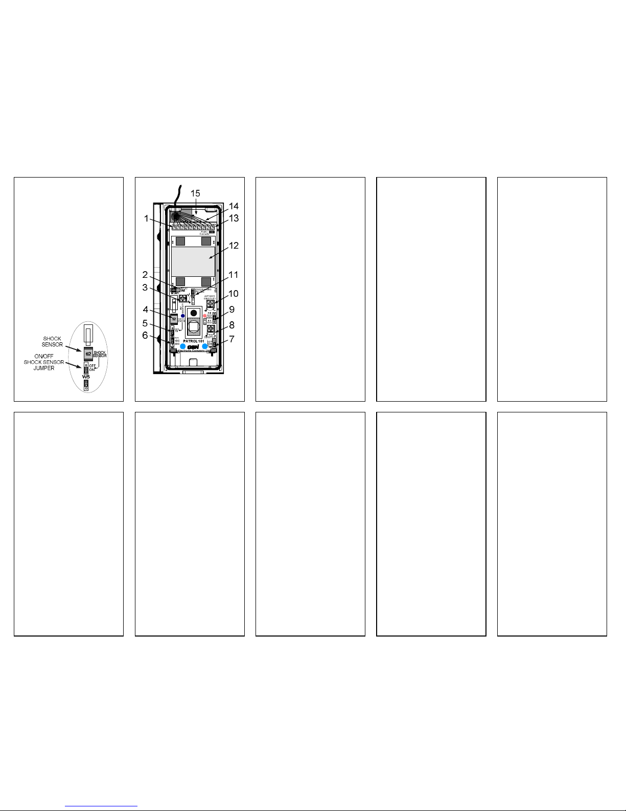
1. POWER SUPPLY CONNECTION
2. JUMPER TO SELECT NC/NO
3. MW SENSITIVITY
4. SHOCK SENSOR
5. ON/OFF SHOCK SENSOR
JUMPER
6. ANIMAL WEIGHT JUMPER
7. ON/OFF LED JUMPER
8. PIR SENSITIVITY ADJUSTMENT
9. OPERATING MODE SETTING
10. ANTI-MASK SENSITIVITY
ADJUSTMENT
11. PULSE PROGRAMMING
JUMPER
12. MW ANTENNA
13. HEATER POWER SUPPLY
CONNECTION
14. ANTI MASK RELAY OUTPUT
(RELAY 2)
15. PIR DETECTOR RELAY
OUTPUT (RELAY 1)
PIR ADJUSTMENT
1. Remove the front cover.
2. Connect the power and
wait for LED to stop flashing
(warm-up time 50 sec).
3. Set Jumper W1 to the
"PIR TEST" position, RELAY 1
is open.
4. Replace the cover.
5. Use the "PIR SENSITIVITY"
potentiometer to adjust the
PIR sensitivity, moving within
the protected area. The red
LED should flash with each
step.
MW ADJUSTMENT
1. Remove the front cover.
2. Set Jumper W1 to the
"MW TEST" position,
RELAY 1 is open.
3. Replace the cover.
4. Use the "MW SENSITIVITY"
potentiometer to adjust the MW
sensitivity, moving within the
protected area.
The blue LED should flash
with each step.
OPERATION MODE
1. Set Jumper W1 to "WORK"
position.
2. Set Jumper W6 according
to animal weight.
3. Replace the cover –LED
will blink. At the same time,
keep the detector field-of-view
clear, until the LED stops
blinking –the anti-mask
function will then be activated
correctly.
Use the “ANTIMASK
SENSITIVITY”potentiometer
to adjust anti-mask sensitivity.
4. Affix the cover with screw.
CHANGING RELAY
SWITCH CONNECTIONS
1. Disconnect the power.
2. Set Jumper W4 to "ON"
position.
3. Restore power.
PULSE-COUNTING METHOD
Selectable pulse count 1, 2, 3,
5, 6 or 7 provides users with the
option of optimizing detector
sensitivity to suit the
environment, thus retaining
reliable performance at all times.
To adjust pulse count for
specific operating environments:
1. Remove Jumper W3.
The blue LED blinks indicating
that pulse counting has begun.
2. Replace Jumper W3 during
pause between LED blinking.
TECHNICAL
SPECIFICATIONS
Input voltage……………….9 –16V
Current consumption:
In standby mode: …………...80mA
In alarm mode:……………..120mА
Heater input voltage….....12 –14V
Heater current
consumption:……………….700mA
Microwave frequency:...10.525GHz
Anti-mask startup (boot)
period:……………..…… 50 ± 5sec
Adjustable mask
detection:……………….0.2 –20cm
Warm up period:…..……50 ± 5sec
Detection range:…...……15meters
Detection speed
range:………………..0.2 –4 m/sec
Relay output:……………………….
………...NC/NO; 60V; 100mA; 16Ω
Tamper output:…...........................
……………..NC; 60V; 100mА; 16Ω
Anti-mask Relay output:…………..
………..NC/NO; 60В; 100mА; 16Ω
Anti-mask alarm activation
delay:…………………......40-60sec
Alarm period:…......................3sec
Reset time:………………..5 ± 1sec
Pulse counting:……...............1 –7
Installation height:………..2.5 –5m
Light immunity:……………………...
…………….no less than 30000 lux
Operating temperature range:
without heater ………–30°C +60°C
with heater ………....–55°C +60°C
Storage temperature
range:....................–60°C –+80°C
Protection rating………………IP65
RFI immunity: 30V/м
at a frequency range 30MHz-2GHz
EMI immunity……………..50,000V
Dimensions:………………………...
…………..55mm x 49mm x 153mm
Weight:…………….…………270gr.
WARRANTY:
GSN Electronic Company Ltd.
warrants the product to be free
from defects in materials and
workmanship under condition
of observance of service
regulations and to be repaired
or replaced under absence of
mechanical damages for a
limited period of five years
from the date of sale.
P/N: USMEPAT101REV.A


