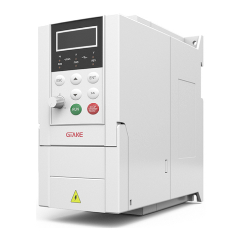
GTAKE GK600E-4T5.5B User manual


Preface
Thank you for choosing GTAKE GK600E Series Elevator Dedicated Drives. This user
manual presents a detailed description of GK600E series with respect to product features,
structural characteristics, functions, installation, parameter setting, troubleshooting,
commissioning and daily maintenance, etc. Be sure to carefully read through the safety
precautions before use, and use this product on the premise that personnel and equipment
safety is ensured.
IMPORTANT NOTES
Please assurethe intactness of product enclosureand all safety covers beforeinstallation.
Operation must conform to the requirements of this manual and local industrial safety
regulations and/or electricalcodes.
Contents of this manual may be subject to appropriate modification as a result of product
upgrade,specificationchangeandupdate of the manual.
In the event of damage or loss of user manual, users may ask local distributors, offices or
our Technical Service Department for a new one.
If any item as stated in this manual is not clear enough, please contact our Technical
ServiceDepartment.
If any anomaly occurs after power up or during the operation, it is essential to stop the
machine and identify the faultor seek technicalservices as soonas possible.
Telephone number of our TechnicalServiceDepartment: (+86) 0755-86392601.

Table ofContents
Chapter 1 Safety Precautions ............................................................................................- 1-
1.1 Safety Considerations........................................................................................- 1-
1.2 Other Considerations.........................................................................................- 5-
Chapter 2 Product Information..........................................................................................- 7-
2.1 Model Explanation..............................................................................................- 7-
2.2 Nameplate Information.......................................................................................- 7-
2.3 Information of Product Model.............................................................................- 8-
2.4 Technical Features of GK600E...........................................................................- 8-
2.5 Parts Drawing...................................................................................................- 11 -
2.6 Appearance,Mounting Dimensions and Weight...............................................- 12-
2.7 External Dimensions of Control Panel..............................................................- 13-
2.8 External Dimensions of Control Panel Bracket.................................................- 13-
Chapter 3 Installation and Wiring....................................................................................- 15-
3.1 Installation Environment...................................................................................- 15-
3.3 Remove & Mount Control Panel and Cover......................................................- 16-
3.4 Configuration of Peripheral Devices.................................................................- 21-
3.5 Terminal Configuration.....................................................................................- 24-
3.6 Main Circuit Terminals and Wiring....................................................................- 24-
3.7 Control Terminal Wiring....................................................................................- 26-

3.8 Control Terminal Specification..........................................................................- 30-
3.9 Control Terminal Usage....................................................................................- 31-
3.10 Instruction of Signal Switches...........................................................................- 37-
3.11 EMISolutions...................................................................................................- 37-
Chapter 4 Operation and Run Instructions.....................................................................- 40-
4.1 Operation of Control Panel...............................................................................- 40-
Chapter 5 Elevator Dedicated Parameters......................................................................- 55-
5.1 Standard Wiring...............................................................................................- 55-
5.2 Elevator Sequence...........................................................................................- 56-
5.3 Startup Manual.................................................................................................- 57-
Chapter 6 List of Parameters...........................................................................................- 75-
Chapter 7 Troubleshooting............................................................................................- 108-
7.1 Fault Causes and Troubleshooting.................................................................- 108-
Chapter 8Maintenance...................................................................................................- 117-
8.1 Routine Inspection..........................................................................................- 117-
8.2 Regular Maintenance.....................................................................................- 118-
8.3 Replacement of Vulnerable Parts...................................................................- 119-
8.4 Storage...........................................................................................................- 120-


GK600E User Manual Chapter 1 Safety Precautions
- 1 -
Chapter 1SafetyPrecautions
Safety Precautions
Safety signs inthis manual:
WARNING: indicates the situation in which the failure tofollow operating requirements
may resultin fireor serious personalinjury orevendeath.
ATTENTION: indicates the situation inwhich thefailure tofollow operatingrequirements
may causemoderate orslight injury and damage to equipment.
Users arerequested toread this chaptercarefully wheninstalling, commissioning and repairing
this product and perform the operation according to safety precautions as set forth in this
chapterwithout violation. GTAKE bears no responsibility for any injury and loss as a result of
any violation.
1.1 Safety Considerations
1.1.1 Prior to Installation
WARNING
Do not touch control terminals, circuit boards and any other electronic parts and
components withbarehands.
Do not use the drivewhosecomponent(s) is/are missing or damaged. Failure to comply
may resultin more faults and/or personalinjury evendeath.
ATTENTION
Check if the product information indicated on the nameplate is consistentwith the order
requirements.If not, do not install it.
Do not install the drive in the event that the packing list does not match the real
equipment.
1.1.2 Installation
WARNING
Only qualified personnel familiar with adjustable frequency AC drives and passenger lift
shouldplanor implement the installation. Failuretocomply may resultin equipment damage
and/or personnelinjuryevendeath.

Chapter 1 Safety Precautions GK600E User Manual
- 2 -
This equipment must be mounted on metal or other flame retardant objects. Failure to
comply may resultinfire.
This equipment must be mounted in an areawhich is away from combustibles and heat
sources.Failuretocomply may resultinfire.
This equipment mustin nocase be mountedintheenvironmentexposedtoexplosivegases.
Failuretocomply may resultinexplosion.
Never adjust mounting boltsof this equipment, especially the oneswithred marks. Failure to
comply may resultinequipmentdamage.
ATTENTION
Handle the equipment gently and take hold of its sole plate so as to avoidfoot injury or
equipment damage.
Mount the equipment where itsweight can bewithstood. Failure tocomply may result in
equipmentdamageand/orpersonnelinjuryif fallinghappens.
Make sure the installation environment conforms to the requirements as stated in
Section 2.4. If not, de-rating is necessary. Failure to comply may result in equipment
damage.
Prevent drilling residues,wire ends and screws from falling into the equipment during
installation. Failuretocomply may resultinfaultsorequipmentdamage.
When mounted in a cabinet, this equipment should be provided with appropriate heat
dissipation.Failuretocomply may resultinfaultsorequipmentdamage.
1.1.3 Wiring
WARNING
Only qualified personnel familiar with adjustable frequency AC drives and passenger lift
should plan or implement thewiring. Failure to comply may result in personnel injury and/or
equipmentdamage.
Wiring must strictly conform to this manual. Failure to comply may result in personnel
injury and/orequipmentdamage.
Make sure the input power supply has been completely disconnected before wiring.
Failuretocomply may resultinpersonnelinjuryand/or equipmentdamage.
All wiring operations must comply with EMC and safety regulations and/or electrical
codes, and theconductor diametershould conformto recommendations of this manual.
Failuretocomply may resultinpersonnelinjuryand/or equipmentdamage.
Since overall leakage current of this equipment may be bigger than 3.5mA, forsafety's
sake, this equipment and its associated motor must bewell groundedso as to avoid risk
of electric shock.
Be sure to implement w iring in strict accordance with the marks on this equipment’s

GK600E User Manual Chapter 1 Safety Precautions
- 3 -
terminals. Never connect three-phase power supply to output terminals U/T1, V/T2 and
W/T3. Failuretocomply may resultinequipmentdamage.
Install braking resistors at terminals and B2 only. Failure to comply may result in
equipmentdamage.
Install DC reactor atterminals and , and removethe jumper connectedat
and . Never connectthis jumper and DC reactortoany other terminals. Failure to
comply may resultin shortcircuitand equipment damage.
Wiring screws and bolts for main circuit terminals must be screwed tightly. Failure to
comply may resultin equipment damage.
AC 220V signal is prohibited from connecting to other terminals than control terminals
RA, RB andRC. Failure to comply may resultin equipment damage.
ATTENTION
Since all adjustable frequency AC drives from GTAKE have been subjected to hi-pot
test before delivery, users are prohibited from implementing such a test on this
equipment. Failure to comply may resultin equipment damage.
Signal wires should be away from main power lines to the best of the possibility. If this
cannot be ensured, vertical cross-arrangement shall be implemented, otherwise
interferencenoisetocontrolsignal may occur.
If motor cables are longer than 100m, it is recommended output AC reactor be used.
Failure tocomply may resultin faults.
1.1.4 Run
WARNING
Drives which have been stored for more than 2 years should be used with voltage
regulator to gradually boost the voltage when applying power to the drives. Failure to
comply may resultin equipment damage.
Be sure to implement the wiring as per Section 3.4 before applying power to the drive.
Failure tocomply may resultin equipment damage and/orelectricshockhazard.
Be sure to confirm the completion and correctness of the drive wiring and close the
cover before applying power to the drive. Do not open the cover after applying power.
Failure tocomply may resultin electric shockhazard.
After applying the power, never touch the drive and peripheral circuits no matter what
statethe driveis under,otherwisetherewillbeelectric shockhazard.
Prior to running the drive, make sure there is no person in surrounding areawho can
reachthemotor soas to preventpersonalinjury.
When the drive is running, foreign bodies should be prevented falling into the
equipment. Failure to comply may resultin faults and/orequipment damage.
+ 2/B1
+ 1
+ 2
+ 1
+ 2

Chapter 1 Safety Precautions GK600E User Manual
- 4 -
Only qualified technicians familiar with adjustable frequency AC drives are allowed to
performsignal test during operation. Failure to comply may result in equipment damage
and/or personalinjury.
Never change the drive parameters atwill. Failure to comply may result in equipment
damage.
ATTENTION
Make sure the number of phases of power supply and ratedvoltage areconsistentwith
productnameplate. If not, contacttheseller or GTAKE.
Check there are no short circuits in peripheral circuits connected with the drive, and
make surethe connectionis tight. Failure tocomply may resultin equipment damage.
Make sure the motor and associated machinery are within allowable range of service
priorto operation. Failure to comply may resultin equipment damage.
Never touchfans, heatsink and braking resistorwith bare hands. Failure tocomply may
result in equipment damage and/or personalinjury.
It is not allowed to start & stop the drivefrequently via direct switching power on or off.
Failure tocomply may resultin equipment damage.
Make sure the drive is in a non-output status before switch-on/switch-off of the drive
output and/or contactor.Failure to comply may result in equipment damage.
1.1.5 Maintenance
WARNING
Only qualified technicians are allowed to implement the maintenance, and
troubleshooting.
Never implement the maintenance, and troubleshooting before power supply has been
turned off and discharged completely. Failure to comply may result in equipment
damage and/or personalinjury.
To avoid an electric shock hazard, wait at least 10 minutes after the power has been
turned off and make sure the residual voltage of the bus capacitors has discharged to
0V beforeperformingany workonthedrive.
After the replacement of the drive, be sure to perform the same procedures in strict
accordancewiththeabove-notedrules.

GK600E User Manual Chapter 1 Safety Precautions
- 5 -
ATTENTION
Do not touch the electric components with bare hands during maintenance, and
troubleshooting.Failure to comply may resultin componentdamage due to ESD.
All pluggable components can be inserted or pulled out only when power has been
turnedoff.
1.2 Other Considerations
1.2.1 Input Power Supply
This series of drives are not applicable to applications out the range of operating voltage as set
forth in this manual. If necessary, please use booster to rise or drop the voltage to regulated
voltagerange.
1.2.2 Surge Protection
This series of drives arefurnishedwithsurgesuppressorthat has certain resistance tolightning
induction. However, users inareas where lightning occursfrequently need to mount an external
surgesuppressorin frontof power inputsideof thedrive.
1.2.3 Operation of Contactor
As to the configuration of peripheral devices recommended by this manual, it is necessary to
mount a contactor between the power supply and input side of the drive. Such a contactor
should not be used as a control device to start and stop the drive, as frequent charging &
dischargingshallreducethe servicelifeof internalelectrolytic capacitors.
When it is necessary to mount a contactor betweenthe drive output andthe motor, it should be
ensured the drive is in a non-output status before switch-on/switch-off of such a contactor.
Failure tocomply may resultin damage to the drive.
1.2.4 Output Filter
Since the drive output is PWM high frequency chopping voltage, mounting filter devices such
as an output filter and an output AC reactor between the motor and the drive shall effectively
reduceoutputnoise, avoidinginterference to other surroundingequipment.
Be sure not to mount phase-shifting capacitor or surge absorber at output side of the drive
sincethis may causedamage tothe driveas aresult of over-temperature.

Chapter 1 Safety Precautions GK600E User Manual
- 6 -
1.2.5 Insulation of the Motor
In view of the fact that the drive output is PWMhigh frequency choppingvoltage accompanied
by higher harmonics, the noise, temperaturerise andvibration of the motor is higher compared
withsinusoidal voltage. Particularly this debases motor insulation. Therefore, the motor should
be subjected to insulation inspection before initial use or reuse after being stored for a long
period of time. The motor in regular service should also be subjected to regular insulation
inspection so as to avoid damage to the drive as a result of motor insulation damage. A 500V
voltage mode mega-ohmmeter is recommended to use for the measurement of the motor
insulation, during which, it is essential to disconnect the motor from the drive. Normally, the
insulation resistanceof the motor should be bigger than 5MΩ.
1.2.6 Derating
Due to the thin air in high-altitude areas, the radiating performance of the drivewithforced air
cooling may degradewhile the electrolyte of electrolytic capacitors is more volatile, whichcan
result in reduction in product life. Drive should be derated when used in an area at the altitude
above 1000meters. It is recommended to derate 1%for every 100mwhen thealtitude is above
1000 meters.

GK600E User Manual Chapter 2 Product Information
- 7 -
Chapter2ProductInformation
2.1 Model Explanation
Model shownon product nameplate indicates theseries name, applicable type of power supply,
power class and the version of software and hardware, etc. via the combination of numbers,
symbols and letters. GK600 E - 4 T 7.5 B
Fig.2-1Productmodel explanation
2.2 Nameplate Information
Fig.2-2Nameplateinformation
Dedicated drive
E:Elevator
4:Power400 V AC
T:Power triphase
B: Brake chopperinbuilt
Product Platform

Chapter 2 Product Information GK600E User Manual
- 8 -
2.3 Information of Product Model
Table 2-1 Product model and technical data
■ GK600E-4T□□□,three-phase400V input,heavy duty
Drive model
Power
rating
(kW)
Rated
output
current
(A)
Rated
input
current
(A)
Applicable
motor (kW)
Brake
chopper
GK600E-4T3.7B
3.7
9.0
10.5
3.7
Inbuilt
GK600E-4T5.5B
5.5
13
14.6
5.5
GK600E-4T7.5B
7.5
17
20.5
7.5
GK600E-4T11B
11
24
29
11
GK600E-4T15B
15
30
35
15
GK600E-4T18.5B
18.5
39
44
18.5
GK600E-4T22B
22
45
50
22
GK600E-4T30B
30
60
65
30
2.4 Technical Features of GK600E
Table 2-2 Technical Features of GK600E
Power input
Rated input
voltage
3-phase
AC380V/AC400V/
AC415V/AC440V/AC460V
Frequency
50Hz/60Hz, tolerance±5%
Voltage
range
Continuous voltage fluctuation ±10%, short fluctuation
-15%~+10%,i.e. 400V:323V~528V
(emergency input:UPS 220VAC,1-phase)
Voltage out-of-balance rate <3%, distortion rate as per the
requirements of IEC61800-2
Rated input
current
See Section 2.3
Power output
Applicable
motor (kW)
See Section 2.3
Rated
current(A)
See Section 2.3

GK600E User Manual Chapter 2 Product Information
- 9 -
Output
voltage(V)
3-phase:0~ ratedinput voltage,error< ±3%
Output
frequency
(Hz)
0.00~ 600.00Hz; unit: 0.01Hz
Overload
capacity
150%- 1min, 180%- 10s,200%- 0.5s every 10min
Control
characteristics
V/f patterns
V/f control
Range of
speed
regulation
1:100
Control
characteristics
Speed
accuracy
±0.5%
Start
torque
0.5Hz: 180%
Basic
functions
Start
frequency
0.00~ 600.00Hz
Accel/
Decel time
0.00~60000s
Switching
frequency
0.7kHz~16kHz
Frequency
setting
Digital setting+ controlpanel ∧/∨
Digital setting+ terminal UP/DOWN
Communication
Analogsetting (AI1/AI2/EAI)
Terminal pulse setting
Motor
start-up
methods
Startedfromstartingfrequency
DC brake start-up
Flying start
Motor stop
methods
Ramp to stop
Coast to stop
Ramp stop + DC brake
Basic
functions
Dynamic
braking
capacity
Brake chopper workingvoltage:650V-750V
Servicetime: 0-100.0s;brakechopper is inbuilt as default
for GK600E lift dedicated drives atGTAKE
DC brake
capacity
DC brake startfrequency:0.00~600.00Hz
DC brake current:0.0~100.0%
DC brake time: 0.0~30.00s

Chapter 2 Product Information GK600E User Manual
- 10 -
Basic
functions
Input
terminals
7 digital inputs, one of which can be used for high-speed
pulse input, and compatible with active open collectors
NPN, PNP and dry contactinput.
2 analog inputs, one of which is voltage/current
programmable, and theother supports voltageonly.
Output
terminals
1 high-speed pulse output, 0~50kHz square wave signal
output. It can output signals such as frequency setting, or
output frequency,etc.
1 digital output
2 relay output
1 analog output, voltage/current outputprogrammable; can
output signals such as frequency setting, or output
frequency,etc.
Protection
functions
Refer to Chapter 7- Troubleshooting
Environment
Place of
operation
Indoors, no direct sunlight, free from dust, corrosive
gases,flammable gases, oil mist,water vapor,water drop
or salt, etc.
Altitude
0-2000m. De-rate 1%for every 100mwhen the altitude is
above1000 meters
Ambient
temperature
-10℃-40℃. The rated output current should be derated
1% for every 1℃whentheambient is 40℃-50℃
Relative
humidity
0~95%,no condensation
Vibration
Less than5.9m/s2(0.6g)
Storage
temperature
-40℃~+70℃
Others
Efficiency at
ratedAmps
Rated power
7.5kW and below : ≥93%
11~ 30kW: ≥ 95%
Installation
wall-mounted
IP grade
IP20
Cooling
method
Forcedair cooling

GK600E User Manual Chapter 2 Product Information
- 11 -
2.5 Parts Drawing
a) GK600E-4T15Band below b) GK600E-4T18.5B~GK600E-4T30B
Fig.2-3Parts drawing
铭牌
下壳体
安装孔
底板
风扇罩
防尘盖板
操作面板
盖板
中壳体
盖板
操作面板
安装孔
机箱
铭牌
风扇
托板
Fan cover
Dust cover
Control
panel
Cover
Control
panel
Cover
Base plate
Mounting
holes
Mounting
holes
Lower
casing
Nameplate
Middle casing
Control
panel
bracket
Fans
Enclosure
Nameplate

Chapter 2 Product Information GK600E User Manual
- 12 -
2.6 Appearance, Mounting Dimensions and Weight
a)GK600E-4T3.7B~ GK600E-4T15B
b) GK600E-4T18.5B~GK600E-4T30B
Fig.2-4External dimensions

GK600E User Manual Chapter 2 Product Information
- 13 -
Table 2-3 Appearance, mounting dimensions and weight
Model
Externaland installation dimensions (mm)
Weight
(kg)
W
H
D
W1
H1
H2
Mounting
hole dia.
GK600E-4T3.7B
120
245
169
80
233
220
5.5
2.9
GK600E-4T5.5B
145
280
179
105
268
255
5.5
3.9
GK600E-4T7.5B
GK600E-4T11B
190
365
187
120
353
335
6
6.2
GK600E-4T15B
GK600E-4T18.5B
270
475
220
170
460
435
8
15.5
GK600E-4T22B
GK600E-4T30B
2.7 External Dimensions of Control Panel
Control panel model of GK600E series Elevator Dedicated Drives is KBU-BX1 whose
appearanceandexternaldimensions areshownin Fig. 2-5.
Fig.2-5External dimensions ofKBU-BX1
2.8 External Dimensions of Control Panel Bracket
A bracketshould beprovided tosupport thepanel and ahole in thecabinet needs to be opened
when the control panel KBU-BX1 needs to be remotely used. Bracket model is KBU-DZ1
whose external dimensions are shown in Fig. 2-6 a). Fig. 2-6 b) shows applicable hole

Chapter 2 Product Information GK600E User Manual
- 14 -
dimensions in the cabinet.
a) External dimensions ofKBU-DZ1 b) Hole dimensionsinthecabinet
Fig.2-6External dimensionsofKBU-DZ1andcabinetholedimensions
Panel TH Hole WTH
1.2mm 73.2mm
1.5mm 74.4mm
2mm 75.5mm

GK600E User Manual Chapter 3 Installationand Wiring
- 15 -
Chapter3InstallationandWiring
3.1 Installation Environment
1)Ambient temperature is in therange of -10℃~40℃.
2)Drive should be installed on surface of flame retardant object, with adequate surrounding
spacefor heatdissipation.
3)Installation shouldbe performedwherevibrationis less than5.9m/s2(0.6g).
4)Protect frommoisture and directsunlight.
5)Protect the coolingfanby avoiding oil, dustand metal particles.
6)Do not expose to an atmospherewithflammable gases, corrosive gases, explosive gases
or other harmfulgases.
7)Prevent drilling residues,w ireends andscrewsfallingintodrive.
8)Ventilation part of the driveshould be installed outsidefromharsh environment (e.g. textile
facilities withfiberparticles andchemicalfacilities filled withcorrosivegases.
3.2 Minimum Mounting Clearances
To ensurefavorable heatdissipation, mount the drive uprighton aflat,vertical and level surface
as per Fig. 3.1. For installation inside cabinet, the product shall be mounted side by side to the
greatest extent while adequate surrounding space shall be preserved for favorable heat
dissipation.
Fig.3-1MinimummountingclearancesofGK600E-4T15Bandbelow
空气流通位置 100mm
100mm
空气流通位置
30mm
30mm
Vent clearance
Vent clearance
This manual suits for next models
7
Table of contents
Other GTAKE Controllers manuals
Popular Controllers manuals by other brands

ProMinent
ProMinent DULCOMETER PH-501 Assembly and operating instructions

Altec Lansing
Altec Lansing 902 Series Technical instructions

PCS
PCS TCM2800 quick start guide

Unitronics
Unitronics UniStream PLC Series installation guide

AirCom
AirCom RH44-S operating manual

Vimar
Vimar BY-ALARM PLUS 03823 quick start guide