Gtec GT804HD User manual

GT804HD
USER MANUAL
04 CHANNEL
DIGITAL VIDEO RECORDER
INSTRUCTION MANUAL
To obtain the best performance and ensure device function correctly, please read this instruction
manual carefully and completely.

2
INSTRUCTION MANUAL
To obtain the best performance and ensure device function correctly, please read this instruction manual carefully and
completely.
FCC Compliance
USER-INSTALLER CAUTION: YOUR AUTHORITY TO OPERATE THIS FCC VERIFIED EQUIPMENT
COULD BE VOIDED IF YOU MAKE CHANGES OR MODIFICATIONS NOT EXPRESSLY APPROVED BY THE
PARTY RESPONSIBLE FOR COMPLIANCE TO PART 15 OF THE FCC RULES.
NOTE: THIS EQUIPMENT HAS BEEN TESTED AND FOUND TO COMPLY WITH THE LIMITS FOR A
CLASS A DIGITAL DEVICE, PURSUANT TO PART 15 OF THE FCC RULES. THESE LIMITS ARE
DESIGNED TO PROVIDE REASONABLE PROTECTION AGAINST HARMFUL INTERFERENCE WHEN THE
EQUIPMENT IS OPERATED IN A COMMERCIAL ENVIRONMENT. THIS EQUIPMENT GENERATES, USES,
AND CAN RADIATE RADIO FREQUENCY ENERGY AND IF NOT INSTALLED AND USED IN
ACCORDANCE WITH THE INSTRUCTION MANUAL, MAY CAUSE HARMFUL INTERFERENCE TO RADIO
COMMUNICATIONS.
OPERATION OF THIS EQUIPMENT IN A RESIDENTIAL AREA IS LIKELY TO CAUSE HARMFUL
INTERFERENCE IN WHICH CASE THE USER WILL BE REQUIRED TO CORRECT THE INTERFERENCE AT
HIS OWN EXPENSE.
THIS CLASS A DIGITAL APPARATUS MEETS ALL REQUIREMENTS OF THE CANADIAN
INTERFERENCE-CAUSING EQUIPMENT REGULATIONS.
WARNINGS, CAUTIONS & COPYRIGHT
WARINGS
TO REDUCE THE RISK OF FIRE OR ELECTRIC SHOCK, DO NOT EXPOSE THIS PRODUCT TO RAIN OR
MISTURE.
DO NOT INSERT ANY METALLIC OBJECT THROUGH VENTILATION GRILLS.
CAUTION
Explanation of Graphical Symbols
The lightning flash with arrowhead symbol, within an equilateral triangle, is intended to alert the
user to the presence of insinuated "dangerous voltage" within the products enclosure that may be of
sufficient magnitude to constitute a risk of electric shock to persons.
The exclamation point within an equilateral rhombus is intended to alert the user to the presence of
important operating and maintenance (servicing) instruction in the literature accompanying the
product.
USERS OF THE SYSTEM ARE RESPONSIBLE FOR CHECKING AND COMPLYING WITH ALL FEDERAL,
STATE, AND LOCAL LAWS AND STATUTES COIPCERNING THE MONITORING AND RECORDING OF
VIDEO AND AUDIO SIGNALS. ULTRAK SHALL NOT BE HELD RESPONSIBLE FOR THE USE OF THIS
SYSTEM IN VIOLATION OF CURRENT LAWS AND STATUTES.
COPYRIGHT
THE TRADEMARKS MENTIONED IN THE MANUAL ARE LEGALLY REGISTERED TO THEIR RESPECTIVE
COMPANIES.
CAUTION: TO REDUCE THE RISK OF ELECTRIC SHOCK.
DO NOT REMOVE COVER (OR BACK).
NO USER-SERVICEABLE PARTS INSIDE.
REFER SERVICING TO QUALIFIED SERVICE PERSONNEL.
RISK OF ELECTRIC SHOCK
DO NOT OPEN
CAUTION

3
TABLE OF CONTENTS
1INTRODUCTION...................................................................................................................... 5
1.1 FEATURE ......................................................................................................................5
1.2 SPECIFICATION..........................................................................................................5
2HARDWARE OVERVIEW...................................................................................................... 8
2.1 FRONT PANEL .............................................................................................................8
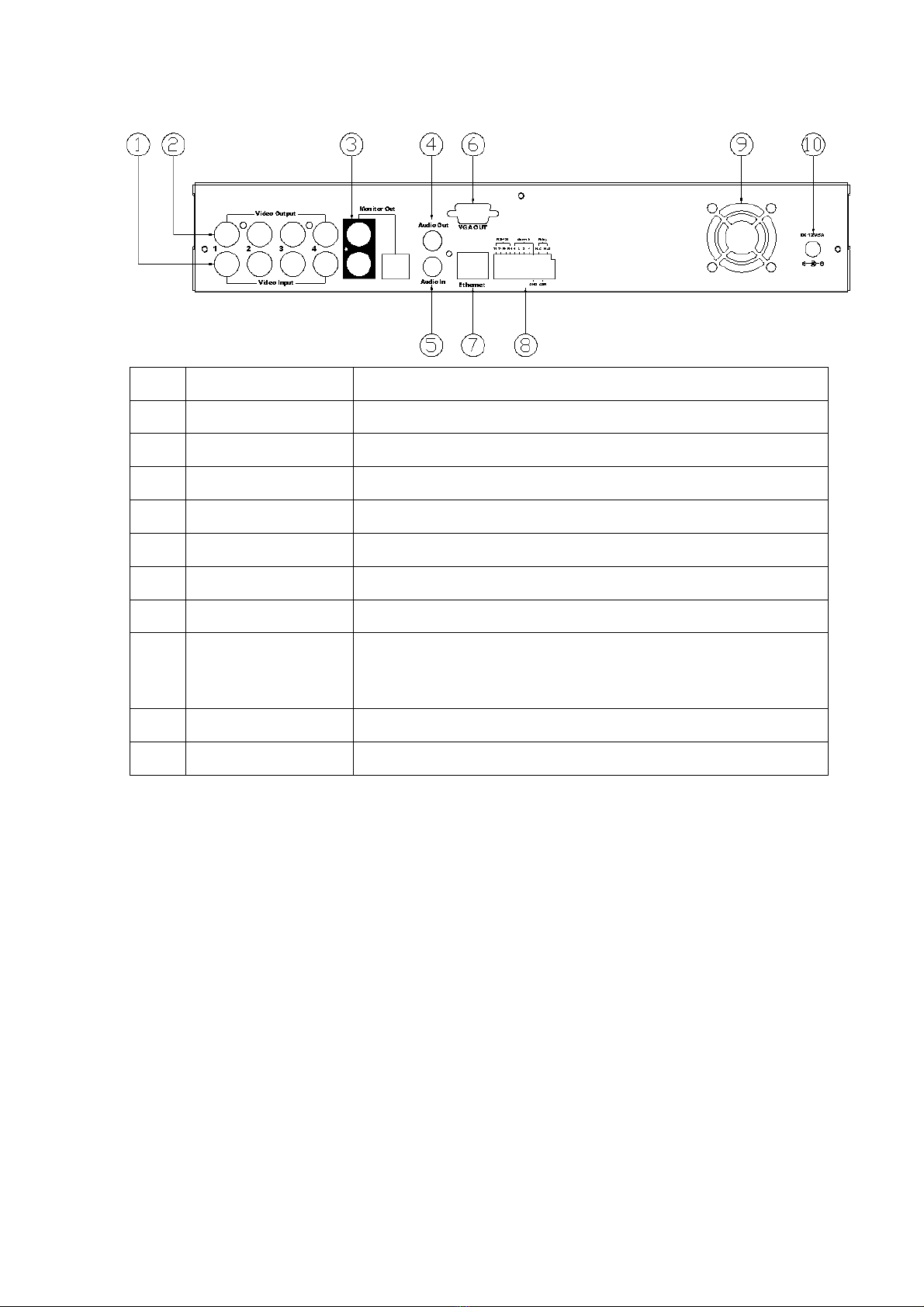
2.2 BACK PANEL................................................................................................................9
2.3 ADVANCED ZOOM, PTZ & COPY KEY CONTROL.............................................9
2.4 CAMERA & MONITOR LOOPING.........................................................................10
2.5 EXTERAL ALARM.....................................................................................................10
2.6 IR REMOTE CONTROL ...........................................................................................12
2.7 PTZ (PAN, TILT AND ZOOM) CAMERA ...............................................................13
3SYSTEM SETUP ..................................................................................................................... 14
3.1 MENU SETUP INTERFACE(GUI)...........................................................................14
3.2 LIVE VIEWING AND POP-UP MENU....................................................................16
3.3 CAMERA SETUP........................................................................................................18
3.4 MOTION SETUP.........................................................................................................20
3.5 RECORD SETUP ........................................................................................................21
3.6 ALARM SETUP...........................................................................................................23
3.7 HARD DISK MANAGEMENT SETUP ....................................................................24
3.8 NETWORK SETUP ....................................................................................................25
3.9 BACKUP SETUP .........................................................................................................26
3.10 SYSTEM SETUP .........................................................................................................29
4DVR PLAYBACK.................................................................................................................... 32
4.1 TIME SEARCH ...........................................................................................................33
4.2 EVENT SEARCH ........................................................................................................34
5BACKUP PLAYBACK ........................................................................................................... 35
5.1 MAIN SCREEN SETTING ........................................................................................35
5.2 CD/DVD BACKUP PLAYBACK ...............................................................................39
5.3 USB & LOCAL BACKUP FILE PLAYBACK .........................................................40
5.4 BACKUP FILE TO AVI ..............................................................................................42
6NETWORK VIEWING & PLAYBACK............................................................................... 43
6.1 IP ADDRESS SETUP ON PC SITE...........................................................................43
6.2 OPTIONAL MICROSOFT INTERNET EXPLORER SETUP..............................44
6.3 LOGIN ..........................................................................................................................47
6.4 REMOTE CONTROL.................................................................................................48
6.5 CONFIGURE ...............................................................................................................53
7. 3GPP APPLICATION & SETTING ..................................................................................... 61
APPENDIX A: RECORDING TIME LAPSE (HOURS)............................................................. 63

4
CIF..................................................................................................................................................... 63
FIELD ............................................................................................................................................... 64
APPENDIX B: HDD COMPATIBLE TABLE .............................................................................. 65

5
1INTRODUCTION
1.1 FEATURE
zH.264 video compression.
z120 PPS
zRecording quality/ rate adjustment per channel available.
zSupport CMS (Central Management System)/ 3GPP.
zAudio Backup / Audio Streaming.
zGraphic User Interface (GUI ).
zSupport time-point backup function under Ethernet remote control mode. User can
select any time period to process backup from remote side.
zSupport time-search & event-search function under Ethernet remote control mode.
zUp to four online clients for independent remote control; individual live-time, play-back
& time-search function available.
zSupport PPPoE/ Static/ DHCP IP & DDNS.
zReal Multiplex, recording/ live-time & playback operation at the same time available.
zID function supplied from IR remote controller. User can control different DVRs at the
same time by using one IR remote controller.
1.2 SPECIFICATION
VIDEO
MODE Multiplex
IMAGE SYSTEM NTSC PAL
LIVE-TIME RESOLUTION 720x480 720×576
LIVE-TIME DISPLAY RATE 4 × 30 Frame / Sec 4 × 25 Frame / Sec
SPLIT SCREEN 1, 4
VIDEO INPUT BNC × 4
VIDEO LOOPING BNC × 4
VIDEO OUTPUT (BNC) BNC × 2
VIDEO OUTPUT (SPOT MONITOR) No
VIDEO OUTPUT (S-VIDEO) Yes
VIDEO OUTPUT (VGA) Yes
AUDIO
AUDIO INPUT RCA × 1
AUDIO OUTPUT RCA × 1
AUDIO BACKUP Yes
AUDIO STREAMING Yes

6
RECORDING
COMPRESSION TYPE H.264
RECORDING RESOLUTION (HALF
D1
)
720×240 720×288
RECORDING RESOLUTION (CIF) 360x240 360x288
RECORDING RATE (HALF D1) 720 x 240 up to 60 PPS 720 x 288 up to 50 PPS
RECORDING RATE (CIF) 360 x 240 up to 120 PPS 360 x 288 up to 100 PPS
COMPRESSION RATE
Low: 1KBytes
Medium: 2.2K Bytes
High: 3.2K Bytes
Best: 6K Bytes
RECORDING MODE Manual / Schedule
PLAYBACK & SEARCH
PLAYBACK SPEED
Fast Forward X 2 X 4 X 8
Fast Backward X 2 X 4 X 8
field by field Playback
Pause
TIME SEARCH Yes
EVENT SEARCH Yes
EVENT LIST 3000 records per H.D.D (Maximum)
OSD & CONTROL INTERFACE
TITLE 8 Characters
ON SCREEN DISPLAY & SETUP Time / Date / Setup Menu
GRAPHIC USER INTERFACE (GUI) Yes
DVR CONTROL PANEL Yes
MOUSE Yes (Optional)
IR REMOTE CONTROLLER Yes (Optional)
3D / 2D Controller Yes
IE BROWSER Yes
PLAYER Yes
STORAGE & BACKUP DEVICE
INTERNAL HDD SUPPORT SATA HDD x 2
USB BACKUP Ye s
CD/ DVD RW BACKUP Yes CD-RW/ DVD-RW
NETWORK
ETHERNET Yes
ETHERNET COMPRESSION
FORMAT H.264

7
DDNS Yes
E-MAIL & FTP Yes
NETWORK IP Static/ Dynamic/ PPPoE
MULTI-REMOTE CLIENT Yes ( 4 Clients at the same time available)
PDA/ CELL PHONE SUPPORT Yes (MPEG4)
3GPP Yes (MPEG4)
ALARM
ALARM INPUT 4 In (NO/ NC)
ALARM OUTPUT 1 Out (NO/ NC)
MOTION DETECTION Yes
MOTION DETECTION AREA 30 x 24 grids
MOTION DETECTION SENSITIVITY 1-100
VIDEO LOSS DETECTION Yes
ALARM RECORDING Yes
BUZZER Yes
SETUP & OTHER FUNCTIONS
DAYLIGHT SAVING TIME Yes
PTZ CONTROL Yes
RS-232 Yes
RS-485 Yes
DIGITAL ZOOM Yes
PASSWORD CONTROL Three levels, one for system, one for HDD format and the
other for Network Password.
KEY-LOCK Yes
MULTI-LANGUAGE Yes
FIRMWARE UPDATE USB Host & Update on line
OTHERS
POWER INPUT DC 12V
POWER CONSUMPTION (W) 15W (Without HDD)
DIMENSIONS (W x H x D) 360mm (W) × 60mm (H) × 311mm (D)
WEIGHT (kg) 4.25kg (Without HDD)
OPERATION TEMPERATURE 0 - 45 ℃

8
2HARDWARE OVERVIEW
2.1 FRONT PANEL
DVR OPERATION
NO. LABEL OPERATION PTZ
1 CD/ DVD RW Slot For CD/ DVD RW.
2 REC
Button Of Recording.
3 LED
Led Indicator
4 1-4 & Quad Press The Button To Display No.1~No.4 Full Screen and
Quad Screen
5 ▲▼◄► Button Of Controller.
Button Of Switching Channel.
UP, DOWN,
LEFT &
RIGHT
6 CONTROL
PANEL Record, Playback And Control Button.
7 USB Connector.
8 USB Mouse Connector (Only by supplied mouse).
9 IR Sensor For Remote Control.
Note: 1. User can select camera by using the channel keys on DVR front panel.
2. Please plug in the supplied mouse to DVR mouse connector before turn on the
DVR. DO NOT REMOVE and PLUG IN the supplied mouse while DVR is
operating.

9
2.2 BACK PANEL
NO. LABEL OPERATION
1 VIDEO INPUT Video input with BNC connector.
2 VIDEO OUTPUT
Video output with BNC connector.
3 MONITOR OUT Video output with BNC and S-Video connector.
4 AUDIO OUT Audio output
5 AUDIO IN Audio input.
6 VGA D-SUB OUT Connect to CRT or LCD monitor.
7 ETHERNET RJ-45 connector for network.
8 RS-485/ ALARM/
RELAY
4 pin D-Sub connector for external control unit, 4 pin D-Sub
connector for Alarm input and 4 pin D-Sub connector for
relay
9 FAN Cooling fan.
10 POWER Power switcher: DC 12V 5A / 50-60 Hz input.
2.3 ADVANCED ZOOM, PTZ & COPY KEY CONTROL
ZOOM :In the full screen mode, user can use “ZOOM” button on the front panel to
perform ZOOM function. Press ▲▼◄►, located on the front panel, to move
the zoom window.
PTZ : When camera supported PTZ function, user can use “PTZ” button, located on the
front panel, to perform PTZ function. Press ▲▼◄► to select and change setup
value.
COPY : Within the playback mode, press “COPY” button to start backup record and
press “COPY” again to end backup.

10
2.4 CAMERA & MONITOR LOOPING
Here recommend link cameras by sequence to avoid unexpected image broken, from CH1,
CH2, CH3, CH4
2.5 EXTERAL ALARM
There are three types of alarms that the system can be configured to handle. They are
Motion detection Alarm, External Alarm and Video Loss Alarm.
A. Motion detection Alarm and External Alarm:
When motion detection or External Alarm was triggered, there are 5 possible actions
will be taken.
a. Changes recording speed as alarm recording speed.
b. Monitor will display corresponding full screen alarm channel, it will switch
automatic mode to manual mode if buttons pressing activity occurred in 5 seconds.
c. Relays can be activated by motion detection or external alarm when turning on.
d. The camera title will be transformed into color of yellow when motion is happening,
“ALARM” text will show up when external alarm is triggered.
B. Video Loss Alarm:
The default setting of Video Loss alarm is enabled.

11
Terminal Connectors:
EXAMPLE 1:Connect Alarm In One with PIR (Passive Infrared).
EXAMPLE 2:Connect with Alarm Siren at Relay N.O.
T+ RS-485 sends +
T - RS-485 sends -
R- RS-485 receives -
R+ RS-485 receives +
ALARM1-4 Camera alarm input.
GND GND.
N.C Relay N.C.
COM Relay COM
N.O Relay N.O.

12
2.6 IR REMOTE CONTROL
ITEM
AUTO Press AUTO to switch channel by channel
automatically.
SEL Press this button to select the different assembled of
camera formats or perform PTZ functions.
.REC Press REC to start recording & again to stop.
1-16 Press the button to select the channel for full screen.
Fast backward
Picture by picture backward play
Picture by picture forward play
Fast forward
Play video forward
MODE Split Screen Switch
ID **ID setup to control DVRs
▲Switch split screen & Move upward or increase.
►Switch split screen & Move right or increase.
▼Switch split screen & Move downward or decrease.
◄Switch split screen & Move left or decrease.
To enter item or make choose.
MENU To into or exit main menu
MENU STOP
MODE
1234
8765
9101112
16151413
AUTO SEL
PB
REC
ZOOM
ID
STOP Stop play and playback
**Each DVR can setup its own ID number. The user can control DVR via remote controller by pressing ID
button first and then ID number of DVR and ID button again of remote controller.
For example, if DVR is set to 1, the user has to press ID button+ 1+ ID button again of remote controller to
control this DVR.

13
2.7 PTZ (PAN, TILT AND ZOOM) CAMERA
Following diagram for DVR connect between PTZ camera & joystick controller, for DVR
to control PTZ camera please make sure the CAMERA ID, BANDRATE (default at 9600
bps) and RS-485 cable.
0 1 0 10 1 0 1
A B A BA B A B
D+ D- D+ D-D+ D- D+ D-
A B A BA B A B
D0+ D0- D1+ D1-D0+ D0- D1+ D1-
A B A BA B A B
R+ R- T+ T-R+ R- T+ T-
DVR 1
ID 1
DVR 2
ID 2
Dome Cam 1
CH 1
ID 1
Dome Cam 2
CH 2
ID 2
Dome Cam 3
CH 3
ID 3
Dome Cam 4
CH 4
ID 4
Dome Cam 1
CH 1
ID 1
Dome Cam 2
CH 2
ID 2
Dome Cam 3
CH 3
ID 3
Dome Cam 4
CH 4
ID 4
DATA+
DATA-
Up to 16CH
D+ D- D+ D-D+ D- D+ D-
Up to 128 ID
Dome Cam 1
ID 1
Dome Cam 2
ID 2
R+ R- T+ T-R+ R- T+ T-
Dome Cam 3
ID 3
Up to 128 ID
Up to 32 ID
Up to 16CH
Up to 4CH Up to 4CH

14
3SYSTEM SETUP
3.1 MENU SETUP INTERFACE(GUI)
A. CAMERASET B. MOTION SETUP
C. RECORDSETUP D. ALARM SETUP
E. HARDDISKSETUP F. NETWORK SETUP

15
G. BACKUPSETUP H. SYSTEM SETUP

16
3.2 LIVE VIEWING AND POP-UP MENU
NOTE:The pop-up menu can be activated by moving the mouse cruise to the bottom
of the live viewing screen.
A. GUI MENU BAR
With live viewing mode, press this button to get into the GUI menu.
B. DISK INFORMATION
With live viewing mode, press this button to display disk information.
C. RECORD BACKUP
With live viewing mode, press this button to backup record (.264 video backup) and
press this button again to finish backup. For performing the single image backup (.Y42
single image backup), press first and then click this button to backup the
necessary image.
D. DIGITAL ZOOM
In the full screen mode, right-click the button of the mouse to pull a range to zoom in
or zoom out the image. User can left-click the button of the mouse to disable this
function. (NOTE: Using the mouse to operate digital zoom can zoom in to max. 16
times.) Moreover, user can also use ZOOM key on the front panel to perform this
function. (First, click ZOOM Key and then click ▲▼◄► key to select zoom in or
zoom out position. Finally, click ENTER key to complete the setting. Moreover, click
ZOOM Key again can disable digital zoom function. Using the panel key to perform
zoom in function is fixed at 2 times.)

17
E. PTZ CONTROLLER
Within live-viewing mode, Clicks this button to get into the PTZ setup menu. User
can also use PTZ key on the front panel to perform this function.
NOTE:Only for the camera supported PTZ function.
PTZ CONTROL
, , , Direction key
/ Zoom In/Out key
PTZ SETUP MENU
Under PTZ control mode, press
into PTZ setup menu.
User can also press the “MENU”
key on the DVR front panel to get
into PTZ setup menu.
User can press key to
process PRESET POINT SETUP To process AUTO function.

18
Pan Speed: User can select the speed of Pan function.
Tilt Speed: User can select the speed of Tilt function.
Auto Speed: User can select the speed of Auto function.
Baud Rate: User can select the fixed Baud Rate for PTZ camera.
Protocol: User can select the fixed Protocol for PTZ camera.
F. AUDIO CONTROL
Press this button to turn the audio on or off。
G. DISPLAY CONTROL
Within live-viewing or playback mode, use display control to switch the camera
channel.
H. RECORD AND PLAYBACK CONTROL
Same as front panel controller and remote controller.
3.3 CAMERA SETUP
Press ▲or ▼to select items.
Press ◄or ►to change values.
Press SET to see more options.
A. CAMERA
Press ◄or ►/ mouse wheel to switch channels.
B. VIDEO ADJUST
B-1. CONTRAST
Press ◄or ►/ mouse wheel to change contrast level.

19
B-2. BRIGHTNESS
Press ◄or ►/ mouse wheel to change brightness level.
B-3. HUE
Press ◄or ►/ mouse wheel to change HUE level.
B-4. COLOR
Press ◄or ►/ mouse wheel to change color level.
B-5. SHAPRNESS
Press ◄or ►/ mouse wheel to change sharpness level.
C. CAMERA TITLE
Use mouse to select and change character.
D. DISPLAY
Press ◄or ►to/ mouse wheel change value for the corresponding camera would be
displayed on the screen or not.
E. AUTO SWITCH
Press ◄or ►/ mouse wheel to ON/OFF auto switch and the switch sec..
F. PTZ SETUP
LEFT-RIGHT SPEED: Use the mouse wheel to change the left-right speed.
UP-DOWN SPEED: Use the mouse wheel to change the up-down speed.
AUTO SPEED: Use the mouse wheel to change the auto detection speed.
BAUD RATE: Use the mouse wheel to change the BAUD rate。
PROTOCOL: Use the mouse wheel to change the connection protocol.

20
3.4 MOTION SETUP
A. CAMERA
Press ◄or ►/ mouse wheel to switch channels.
B. MOTION DETECT
Press ◄or ►/ mouse wheel to change value for motion detect function.
C. BUZZER
Press ◄or ►/ mouse wheel to change value for buzzer while motion detected.
D. SENSITIVITY
Press ◄or ►/ mouse wheel to change sensitivity value from 001 (minimum) to 100
(maximum).
E. AREA SETUP
1. Press SET to enter Motion Area Setting. (Note: The default setting of all area is
“MOTION ON”.)
2. Use the mouse to select which block is needed.
Press ▲or ▼to select items.
Press ◄or ►to change values.
Press SET to see more options.
The green area shows the area
without motion detection.
Table of contents
Other Gtec DVR manuals