GuardAir AIRSPADE 2000 User manual

A DIVISION OF
®
AIRSPADE 2000
OPERATOR'S MANUAL

TECHNICAL SPECIFICATIONSTABLE OF CONTENTS
2
Technical Specifications 3
General Information 4
Safety Instructions 5
Assembly Instructions 6
Operating Instructions 7-9
Components & Accessories 10-12
Parts Disassembly and Reassembly 13
Products, Parts & Accessories List 14
Limited Warranty 15
AirSpade® is a registered trademark of Guardair Corporation.
Always wear eye and ear protection when
operating air tools and related equipment.

TECHNICAL SPECIFICATIONS
3
AIRSPADE SERIES 2000
•Overall Length 60.5 inches (154 cm)
•Weight 7.1 pounds (3.2 kg)
•Nozzle Extra-hardened stainless steel
•Nozzle Flow Rates 25 scfm (0.7m3/min)
60 scfm (1.7m3/min)
105 scfm (3.0m3/min)
150 scfm (4.2m3/min)*
225 scfm (6.4m3/min)
•Operating Pressure 90 psi (6.2 bar)
•Barrel Insulated fiberglass
•Inlet 3/4” FNPT
*Standard Model
AirSpade is covered by U.S. Patents 5,782,414, D408,830, and D435,207.

GENERAL INFORMATION
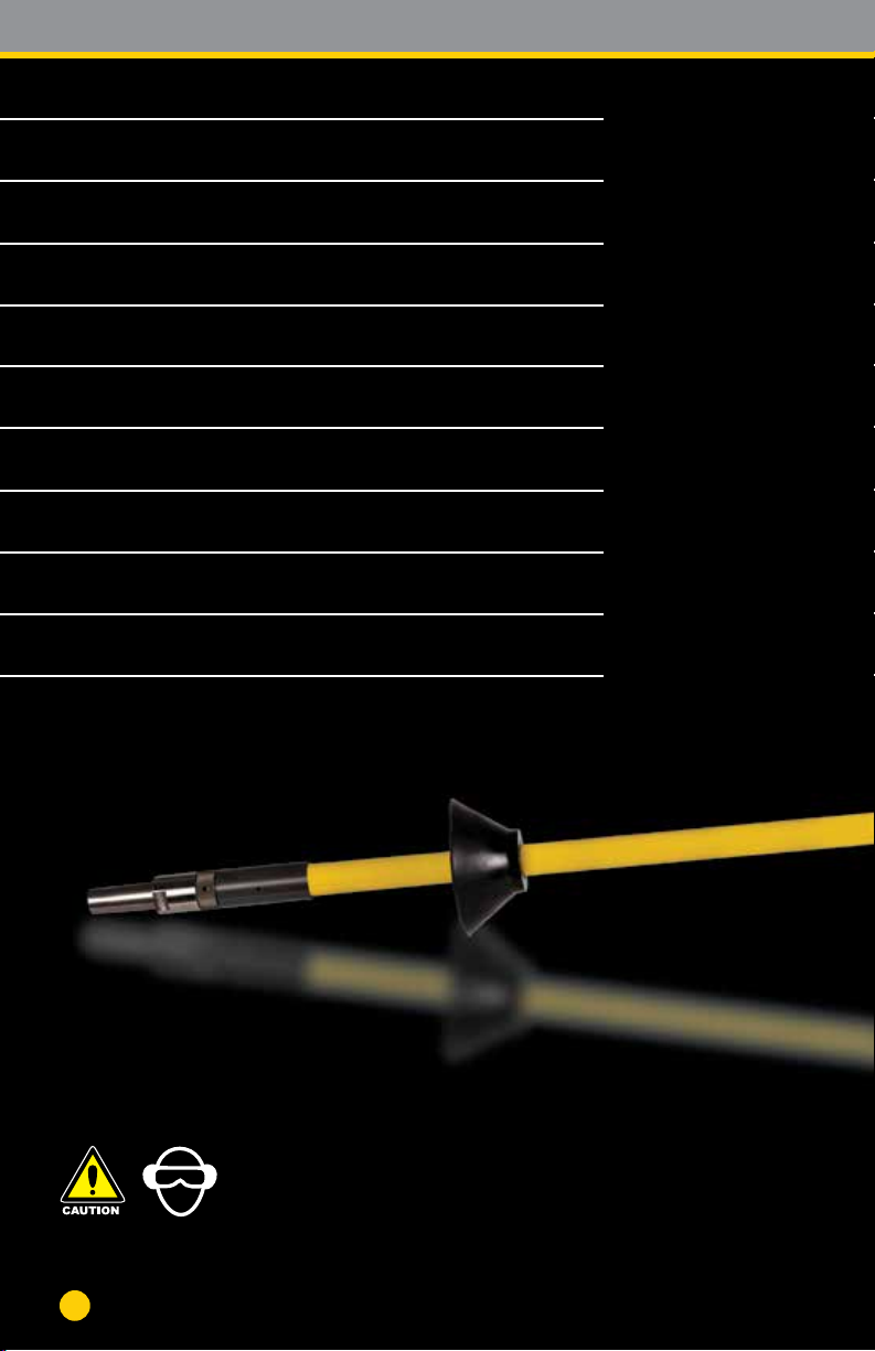
GUARDAIR CORPORATION’S AirSpade Series 2000 is a compressed air-
powered tool used for excavation of a wide variety of soils. AirSpade Series 2000
consists of an ergonomic pistol grip style handle, an insulated fiberglass barrel,
and a patented supersonic nozzle. Typically powered by a portable tow-behind
air compressor, the AirSpade Series 2000 provides a safe, powerful and
efficient method of uncovering underground electric lines, pipes, and tree roots
without harm. Capable of excavation where a shovel or backhoe cannot be used,
AirSpade can be equipped with multiple nozzle sizes and a variety of extension
lengths for optimum job performance.
The heart of the AirSpade is the patented supersonic nozzle which produces a
focused “laser-like” jet of air moving at approximately 1,200 mph (1,900 km/hr),
or nearly twice the speed of sound. This supersonic air-jet penetrates voids in
the soil and expands rapidly, therefore fracturing the soil. Unlike the hard cutting
edges of shovels, picks, blades, or buckets, the air-jet is harmless to non-porous
items such as tree roots, buried pipes, or cables. Excavating with AirSpade is
much easier and many times faster than hand excavation.
The AirSpade supersonic air-jet outperforms “homemade tools” featuring a pipe
nipple or a crimped orifice. Air flow from these tools expands to atmosphere in
an unfocused, complex manner while the supersonic air jet delivers significantly
more kinetic energy and more focused momentum. In practical terms the
AirSpade does more work by moving more material, and harder material, in a
shorter period of time.
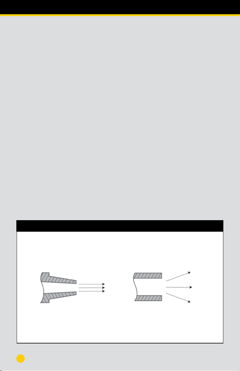
(Fig.A)
FOCUSED AIR FLOW FROM
AirSpade SUPERSONIC NOZZLE
(Fig.B)
UNFOCUSED AIR FLOW FROM
IMPROPERLY DESIGNED NOZZLE
AirSpade’s patented supersonic nozzle turns compressed air into a high-speed, laser-like jet moving at twice
the speed of sound – 1,200 mph. All of the energy and momentum of air moving at approximately Mach 2
is focused into the soil, dislodging it in a fraction of a second. (Fig.A) The result is faster, safer, and more
efficient soil excavation.
Air exiting from an improperly designed nozzle diffuses outward 3 to 4 times wider than the air-jet from the
patented AirSpade supersonic nozzle. (Fig.B).
4
AIRSPADE PATENTED SUPERSONIC NOZZLE

SAFETY INSTRUCTIONS
5
•Wear appropriate protective work clothing and equipment. Cut and puncture resistant
gloves, approved safety glasses with side shields and/or face protection, and protective
earplugs or earmuffs should be worn while operating the AirSpade. Eye protection should
comply with ANSI Z87.1-2015. Ear protection should provide a NRR of at least 20 dB.
•Wear approved respiratory protection when working in extremely dusty conditions.
•Wear approved, electrically insulated footwear and gloves if working near underground
electrical lines.
•Ensure that all personnel near the area being excavated are aware that AirSpade is being used
and that they wear appropriate personal protection as indicated.
•Protect surfaces that could be chipped, or damaged by dislodged soil or rock particles
adjacent to the excavation work area by using suitable drop cloths, screens, or other means.
•Check the AirSpade for loose or damaged parts prior to use. Tighten, repair,
and/or replace as necessary.
•Inspect hoses for leakage, kinking, abrasion, corrosion, or any other signs of wear or
damage. Worn or damaged hose assemblies should be replaced immediately.
•Check that the air compressor is delivering the specified pressure to operate the AirSpade.
•Anticipate that the AirSpade tool will push upwards when using the 45 degree adapter.
Brace against the upwards force by holding the tool in accordance with the operating
instructions. See page 13.
ALWAYS
•Operate the AirSpade until the operating and safety instructions are read and fully understood.
•Make any modifications to the AirSpade.
•Tie, tape, or otherwise lock or fasten the trigger in the “ON” position.
•Point, or aim the AirSpade at any person during operation.
•Allow hands, feet, or any body parts near the AirSpade nozzle tip during operation.
•Use the AirSpade as a pry bar.
DO NOT

ASSEMBLY INSTRUCTIONS
6
User assumes full responsibility to read and understand these
instructions prior to operation. Failure to adhere to these instruc-
tions can result in personal injury. User should also have operating
knowledge of the air compressor to which the tool is attached.
NOZZLEBARREL
BA
HANDLE
• Read and follow the directions below to properly assemble the AirSpade.
• Apply a small amount of commercial grade anti-seize compound on the barrel
threads (A & B) to prevent galling. Screw the nozzle into the barrel by turning
clockwise. Hand-tighten only.
• Screw the barrel into the handle by turning clockwise. Hand-tighten only.

7
Maximum Recommended Air Supply
Hose Length (Feet)
Nozzle Flow 3/4” ID 1” ID 1
1/4” ID
(scfm)
25
60
105
150
225
4,750
900
240
110
40
≤5,000
3,460
1,110
520
220
≤5,000
≤5,000
3,350
1,730
880
STARTING
• Start the air compressor according to the manufacturer’s instructions.
• The air compressor should build pressure until 100 – 120 psig is shown on the
air compressor pressure gauge.
• Make sure that the AirSpade is turned off. Point the nozzle away from all
personnel or loose objects that could become airborne. Open the air supply
valve on the air compressor.
• Securely hold the AirSpade. Point the nozzle up and away from all personnel and
any loose objects, and depress the trigger. Read the air compressor pressure
gauge and the pressure gauge on the tool. During operation the air pressure
gauge on the tool should read between 80 and 100 psig (5.5 and 6.9 bar). If
not, adjust the output pressure of the air compressor.
BEFORE OPERATION
• Match the air compressor size to the AirSpade nozzle on the tool. To properly
size the air compressor, make sure the air compressor flow rate is equal to, or
greater than, the nozzle flow rate.
• Check the air compressor for sufficient fuel and oil levels.
• Make sure the air compressor is secure from accidental motion.
• Close the air supply valve on the air compressor.
• Make sure all air supply hose
connections are secure and
safety clips are installed.
• Use air supply hose with a
pressure rating equal to, or
greater than, 150 psig.
• Use air supply hose of an
appropriate diameter and
length. (See Table)
OPERATING INSTRUCTIONS

8
OPERATING INSTRUCTIONS
EXCAVATION PROCEDURES
•
For most excavations the best performance is achieved by holding the AirSpade noz-
zle at approximately a 45 degree angle from horizontal and about 1 inch away from
the surface to be excavated.
•
Depending on the soil type, the AirSpade should be directed above the surface to be
excavated at a rate of approximately 1 to 2 feet per second (0.3 to 0.6 meters per
second).
•
Except in very hard and compacted clays, dwelling on the same spot tends to reduce
the rate at which material is excavated and can increase the amount of material
blown away from the excavation site.
•
Watering the work area ahead of time can often be helpful. Watering
reduces airborne dust if the soil is extremely dry. It also reduces the soil strength
making digging easier.
•
For small diameter holes, position the AirSpade barrel perpendicular to the ground
with the nozzle close to the surface. Depress the trigger, and slowly thrust the tool
into the soil. When resistance is met, slowly withdraw the
AirSpade and then reinsert. This procedure allows loose soil at the bottom of the
hole to exit upwards. Reinsert the nozzle and repeat the above procedure until the
desired depth of hole is reached.
•
When boring a small diameter hole, or when plunging the AirSpade into loose soil,
the tendency to expose the operator to blown back material is increased. The adjust-
able dirt shield should be positioned close to the ground to deflect airborne material
away from the operator.
•
For large diameter holes, position the AirSpade at an angle between 30° and 45°
from the horizontal. Depress the trigger and move the AirSpade back and forth
across the footprint of the excavation to loosen the soil to a depth of several inches.
Each layer of loose soil should then be removed with a shovel or vacuum. Repeat the
procedure until the desired depth is reached.
•
For shallow, wide excavations, position the AirSpade at an angle between 30° and
45° from the horizontal. Depress the trigger, move the nozzle from side to side the
desired width, and blow the loosened soil ahead of the nozzle. Continue until the ex-
cavation is completed to the required length.

OPERATING INSTRUCTIONS
9
•
For deeper excavations or trenches loosen the soil in layers of several inches.
Remove the soil with a shovel or vacuum. Repeat the procedure until the desired
depth is reached.
•
Excavation rates will vary depending
upon soil composition, soil compaction,
and the air delivered from the AirSpade
nozzle. (See Table)
•
Use a portable (collapsible) barrier or
fence constructed from plywood, or
canvas cloth, to keep dislodged soil
confined to the working area.
SHUT DOWN
•
Turn off the air compressor air supply valve.
•
Shut down the air compressor.
•
Securely hold the AirSpade. Point the nozzle up and away from all personnel and
any loose objects, and depress the trigger. Continue to depress the trigger until all
compressed air from the tool and hose is fully expelled and the air pressure gauge
on the AirSpade reads “0”.
•
It is now safe to disconnect the air supply hose. Store the AirSpade as desired.
MAINTENANCE
•As with any professional grade tool, the AirSpade requires regular care to ensure
proper operation. Prior to each use, inspect the tool for any loose or visibly damaged
parts. Tighten or replace worn parts as required. Brush off dirt or other foreign
material from around the trigger and valve stem areas. Periodically apply light oil or
lubricant (e.g. WD40) to the exposed valve stem to ensure smooth operation.
Soil Excavation Rates
Nozzle Flow Soil Excavation Rate
(scfm) (cubic ft / min)
25 0.4 to 0.9
60 0.7 to 1.1
105 0.9 to 1.5
150 1.2 to 1.8
225 1.7 to 2.3

COMPONENTS & ACCESSORIES
10
NOZZLE
•
The AirSpade nozzle can be unscrewed from the barrel by turning counter-
clockwise. In the event of a tighter than normal connection, flats are provided
on the nozzle for wrench application. Before re-installing the nozzle, remove any
dirt or foreign material from the threads and o-ring, and apply a small amount of
commercial grade anti-seize compound on the threads to prevent galling. Screw
the nozzle into the barrel by turning clockwise. Hand-tighten only.
BARREL
•
The fiberglass barrel can be unscrewed from the handle by turning counter-
clockwise. In the event of a tighter than normal connection, a spanner wrench
may be used on the barrel if necessary. Before re-installing the barrel into the
handle, remove any dirt or foreign material from the threads and o-ring, and apply
a small amount of anti-seize compound on the threads to prevent galling. Screw
the barrel into the handle by turning clockwise. Hand-tighten only.
EXTENSIONS
•
Extensions provide the ability to extend the reach of the AirSpade into deeper
holes or trenches. To install an extension, first remove the nozzle. Apply a small
amount of anti-seize compound on the threads of the barrel, then attach the
extension to the barrel by screwing it into the barrel. Turn clockwise and hand-
tighten only. Apply a small amount of anti-seize compound on the threads of the
extension, then screw on the nozzle. Hand-tighten only.

11
COMPONENTS & ACCESSORIES
45º ADAPTER
• The 45º adapter enables the AirSpade to operate in
tight locations where obstructions do not allow the use
of a straight barrel. It can be installed by hand with no tools required.
Remove the existing nozzle from the barrel. Ensure the 45º adapter locking
ring is shouldered against the 45º adapter body and the 45º adapter coupler
is snug against the o-ring. Clean the threads and the o-rings on the barrel and
on the 45º adapter assembly and apply anti-seize compound to the threads of
both. Screw the 45º adapter assembly onto the barrel via the coupler. Hand-
tighten only. Screw the nozzle onto the other end of the 45º adapter. Hand-
tighten only. To lock the adapter into position, shoulder the locking ring against
the coupler. Do not thread 45º adapter into AirSpade handle.
CAUTION: When using the 45º
adapter, compressed air exiting
the nozzle will force the tip of the
tool away from the direction the
nozzle is aimed. To prevent this
from occurring, the operator
should place the free hand at least
midway down the barrel. Grip the
barrel tightly to brace the tool
against the force produced by the
exiting compressed air.
Barrel Connector
Barrel
Barrel Sleeve
O-Ring (Not Shown) Nozzle
45º Adapter Body
45º Adapter Coupler
45º Adapter Locking Ring

COMPONENTS & ACCESSORIES
12
SLIDING DIRT SHIELD
•
The sliding dirt shield is made up of two components: the locking sleeve (A)
and rubber deflector (B). One end of the locking sleeve has 4 slots; the other
end is solid.
•
To install, slide the rubber deflector over
the nozzle and coupling into position (C) on
the barrel. Separate the locking sleeve and
clamp over the barrel in position (D).
Make sure the slots are closest to the
nozzle. (Fig.1)
•
Slide the rubber deflector so that it is posi-
tioned over the solid end of the locking sleeve.
The locking sleeve and rubber deflector as-
sembly can now slide freely up and down the
barrel shaft. (Fig.2)
•
To lock the sliding dirt shield in position,
slide the assembly to the desired position
on the barrel. Then firmly push the rubber
deflector over the slotted end of the locking
sleeve. (Fig.3)
AB
E
Fig. 3.
Locking Sleeve
Rubber Deflector
Fig. 2.
NOZZLE
COUPLING
Fig. 1
DC
NOZZLE
COUPLING

PARTS, DISASSEMBLY AND RE-ASSEMBLY
13
A
B
CD
E
G
F
Parts List
A Handle Assembly
B Gauge
C Gauge Seal
D Valve Cap
E Spring
FValve Seal
GValve Stem
TOOLS NEEDED
• 1/2” square drive
• PTFE thread sealant tape
• Pick or flathead screwdriver
• 15/16”, 6-point socket
REPLACING PRESSURE GAUGE
Step 1: Remove gauge seal with pick or small flathead screwdriver.
Step 2: Remove pressure gauge with 15/16” socket and discard.
Step 3: Apply thread sealant tape to threads of new pressure gauge – do not
block air inlet of the pressure gauge.
Step 4: Thread new pressure gauge into handle and tighten with 15/16”
socket. Do not over tighten.
Step 5: Insert new gauge seal.
REPLACING VALVE COMPONENTS
Step 1: Remove valve cap with 1/2” square drive.
Step 2: Remove and discard the spring, valve seal, and valve stem.
Step 3: Clean and inspect valve stem and bronze bushing.
Step 4: Apply lubrication (included) to the new valve stem and insert into the
handle.
Step 5: Insert the new seal with the black seal face facing downwards.
Step 6: Insert the new spring.
Step 7: Apply thread sealant tape to the threads of the existing valve cap.
Step 8: Use 1/2” square drive to thread valve cap into the handle. Firmly tighten.
INSTRUCTIONS

Part # Description
HT114 AIRSPADE 2000 105 CFM CONSTRUCTION KIT
HT106 AIRSPADE 2000 150 CFM CONSTRUCTION KIT
HT102 AIRSPADE 2000 225 CFM CONSTRUCTION KIT
HT142 AIRSPADE 2000 105 CFM ARBOR/LANDSCAPE KIT
HT107 AIRSPADE 2000 150 CFM ARBOR/LANDSCAPE KIT
HT109 AIRSPADE 2000 225 CFM ARBOR/LANDSCAPE KIT
HT108 AIRSPADE 2000 TRENCH RESCUE KIT
HT134 AIRSPADE 2000 60 CFM WITH 4 FT BARREL
HT139 AIRSPADE 2000 105 CFM WITH 4 FT BARREL
HT116 AIRSPADE 2000 150 CFM WITH 3 FT BARREL
HT130 AIRSPADE 2000 150 CFM WITH 4 FT BARREL
HT138 AIRSPADE 2000 225 CFM WITH 4 FT BARREL
HT126 25 CFM NOZZLE
HT125 60 CFM NOZZLE
HT156 105 CFM NOZZLE
HT123 150 CFM NOZZLE
HT127 225 CFM NOZZLE
HT119 45 DEGREE ANGLED ADAPTER
HT131 AIRSPADE 3 FT BARREL WITH DIRT SHIELD
HT118 AIRSPADE 4 FT BARREL WITH DIRT SHIELD
HT121 AIRSPADE 3 FT EXTENSION WITH COUPLER
HT154 AIRSPADE 4 FT EXTENSION WITH COUPLER
HT120 AIRSPADE 5 FT EXTENSION WITH COUPLER
HT180 AUXILIARY HANDLE ASSEMBLY
HT117 AIRSPADE 2000 HANDLE ASSEMBLY
HT150 AIRSPADE 2000 HANDLE REPAIR KIT - PRE 2010 MODELS
HT150-1 AIRSPADE 2000 HANDLE REPAIR KIT - 2010 to 2020 MODELS
HT150-2 AIRSPADE 2000 HANDLE REPAIR KIT - CURRENT MODELS
HT57 10 FT x 1” ID LIGHTWEIGHT AIR SUPPLY HOSE
HT111 25 FT x 1” ID LIGHTWEIGHT AIR SUPPLY HOSE
HT112 50 FT x 1” ID LIGHTWEIGHT AIR SUPPLY HOSE
HT113 50 FT x 1” ID STANDARD AIR SUPPLY HOSE
HT132 STORAGE CASE
HT136 FACE SHIELD & HEADGEAR
14
PRODUCTS, PARTS & ACCESSORIES LIST

15
LIMITED WARRANTY
Limited Warranty
IN NO EVENT SHALL GUARDAIR CORPORATION BE LIABLE TO THE PURCHASER OR ANY USER OF THE
AIRSPADE, OR TO ANY OTHER PERSON OR ENTITY, FOR INDIRECT, INCIDENTAL, OR CONSEQUENTIAL
DAMAGES INCLUDING THE COST OF PROVIDING SUBSTITUTE EQUIPMENT DURING PERIODS OF
MALFUNCTION OR NONUSE AND DAMAGES FOR DELAY. THE WARRANTIES AND REMEDIES SET
FORTH ABOVE ARE THE SOLE AND EXCLUSIVE WARRANTIES AND REMEDIES AVAILABLE. GUARDAIR
CORPORATION SPECIFICALLY DISCLAIMS ALL IMPLIED WARRANTIES OF MERCHANTABILITY AND
FITNESS FOR A PARTICULAR PURPOSE AND ALL OTHER WARRANTIES, WHETHER EXPRESS, IMPLIED
OR STATUTORY.
AirSpade Series 2000 is warranted by GUARDAIR CORPORATION (GUARDAIR)
against defects in material and workmanship for a period of one year. Defective
units will be replaced or repaired at the option of GUARDAIR. The warranty period
begins at the date of shipment of the tool from GUARDAIR or from GUARDAIR’S
authorized distributor.
This warranty shall not be in effect if the tool is subject to misuse, negligence,
or accident, or if it is configured, or used in any manner inconsistent with the
directions set forth in this operator’s manual. Wear and tear from normal use is
not covered under this warranty.
Any and all claims for warranty consideration must be coordinated through
GUARDAIR. Do not return the unit or parts without prior authorization. Upon
obtaining authorization, returned units or parts must be postage prepaid.
The purchaser’s recovery for damages resulting from any and all causes
whatsoever, including, but not limited to, breach of contract, breach of warranty,
negligence or strict product liability will be limited to the replacement of the
components of the tool with respect to which losses or damages are claimed,
provided that GUARDAIR has been notified of any alleged defect within the
warranty period.

AirVac and AirSpade 2000 – the ideal combination to safely uncover
sensitive tree roots and underground objects without harm.
Powered by a 185 cfm tow-behind compressor, AirVac is the mobile
alternative to large, expensive vacuum trucks. Effectively vacuums up to
2 cubic ft/min of spoils including dirt, sand, gravel, small rocks, and muck.
•Heavy-duty, all aluminum construction with 82 gallon tank
•24" x 16" dump door
•Removable, venturi vacuum engine assembly
•15" diameter pneumatic tires
•4" ID x 15 ft heavy-duty, lightweight vacuum hose
• 4" ID x 4 ft clear plastic vacuum wand
The Perfect Companion for AirSpade
®
®
47 Veterans Drive • Chicopee, MA 01022-1062
Toll-Free: 800-482-7324 | Local: 413-594-4400
20269 HT35-2
This manual suits for next models
7
Table of contents
Popular Lawn And Garden Equipment manuals by other brands

MO-EL
MO-EL MO-STICK INOX 372 Use and maintenance

FLORABEST
FLORABEST 106625 Operation and safety notes

Yard Works
Yard Works 060-0194-4 instruction manual

Gardeners
Gardeners 8598238 quick start guide

ThePondguy
ThePondguy PondShelter 160350 Installation & maintenance manual

MO-EL
MO-EL MO-STICK INOX 372 Use and maintenance

FLORABEST
FLORABEST fhe 550 a1 translation of original operation manual

Garten Meister
Garten Meister GM EMT 500 instruction manual

FLORABEST
FLORABEST HG04444A manual

Avantco
Avantco Collecting Lawn Mower 1200 A21315 Operator's manual

Dura Trel
Dura Trel 11183 Assembly instructions

Dura Trel
Dura Trel winchester TRELLIS Assembly instructions