Gude GSE 4700 RS User manual

GSE 4700 RS
# 40631
English GB
Translation of original operating instructions
Generator
.
©Güde GmbH & Co. KG - Birkichstrasse 6 - D-74549 Wolpertshausen - Deutschland

1
8
3
4
5
6 2
7
11
12
13
14
15
A
1
23
2

GB Please read the operating manual carefully before starting the machine.
A.V. 2
For reprints, even partial, permission required. Technical changes reserved.
Translation of original operating instructions!
GB
Any technical questions? Complaints? In need of spare parts or operating manual?
On our web pages www.guede.com we will help you fast and without needless bureaucracy. Please help us so we can help you. To identify
your machine in case of any claim, we need to know serial number, product number and year of production. You can find all these data on the
type label. To have them handy please write them down in here:
Serial number:___________________________Product number:______________________Year of production:____________________
Tel.: +49 (0) 79 04 / 700-360
Unit
Synchronous generator with a large tank.
AVR (automatic voltage control to facilitate a stable output)
Generator to drive ohmic and induction appliance such as lighting chains, power hand tools (drills, chain saws, compressors ). To be
connected to stationary installations – heating, electric network, air conditioning – or to supply caravans – it is necessary to
consult a specialised electrician.
We should not be held liable for any damage resulting from non-observance of these instructions.
Outfit (regular)
Socket with 230 V/ 10 A protection pin, overloading fuse, oil shortage protection
A critical point of separate induction appliances is the machine start up input. The input may be as much as a treble
of nominal capacity. This should be always taken into account.
Scope of Delivery
Fig. 1
1. Frame
2. 2 x 230 V sockets
3. Voltmeter
4. Oil replenishment plug
5. Oil discharge screw
6. engine switch
7. Oil level indicator
8. Overloading switch
9. Ignition plug wrench
10. Wrench handle
11. Tank
12. Bowden starting cable
13. Starting unit
14. Air filter case
15. Fuel cock
16. Exhaust
17. Exhaust pipe
18. Generator cover
19. Fuel level indicator
20. Tank cover
21. Valve lid
22. Choke
Warranty
A warranty period of 12 months applies to commercial use and 24 months apply to private use and commences on the day of
purchase of the device.
Warranty applies exclusively to failures due to defective material or workmanship. An original sale slip with indication of date of sale
must be presented in case of claiming for the warranty rights.
Warranty does not cover unprofessional use such as device overload, violent use, damage caused by third party or foreign materials,
failure to comply with operations and assembly manual, and normal wear and tear.
General Safety Instructions
Prior to the initial use of the unit, the operating instructions should be read completely. If in doubt with regard to connection and
operation of the unit, consult the manufacturer (servicing department).
11

FOLLOW THE INSTRUCTIONS BELOW CAREFULLY IN ORDER TO SECURE A HIGH DEGREE OF SAFETY:
CAUTION!
•Invite a professional electrician when connecting the generator to a house supply source to check the
connection and grounding.
•The generator in operation should always be earthed via a grounding pin!
•Always place the generator on firm flat base!
•Never use the generator in closed spaces. The flue gases may be fatal.
•Never cover up the generator.
•Never touch it with wet hands.
•Do not work in moist conditions.
•Never connect 2 generators together.
Use of the electric tools requires observance of the attached safety instructions and accessory safety instructions.
A risk of injury or damage of the electrical tool.
The appliance technical data should match the safety instructions on the generator. (With start up output, 3-
5 multiple of the connected unit nominal output should be observed).
Behaviour in case of emergency
Provide necessary first aid treatment corresponding to the injury nature and seek qualified medical help as soon as possible.
Protect the injured person from other injuries and calm him/her down.
First aid kit must always be available in the place of your work in case of accident in accordance with DIN 13164. Material
taken out of the first aid kit needs to be supplemented right away.
If help is needed, please provide the following details:
1. Place of accident
2. Accident nature
3. Number of injured persons
4. Injury type
Signs on Unit
Meaning of Symbols
Symbols shown below are used throughout this manual and/or on the unit:
Product Safety:
Product compliance
with respective EU
standards
Bans:
General ban
combined with
another pictograph
No smoking, no fire,
unprotected light Do not use the unit
in rain
Warning:
Warning/Caution Do not use the unit
in closed operation
spaces
Commands:
Use ear protectors Read instruction
manual carefully
before use
12

Environment Protection:
Wastes to be
disposed of in a
professional manner
not to harm the
environment.
Cardboard
packaging to be
collected for
recycling.
Faulty and/or
disposed of
electrical/electronic
appliances to be
collected by
authorised salvage
places.
Packaging:
Protect from
moisture Keep Up Fragile
Technical Data:
Watt A
Connection Current intensity Voltage/Frequency Engine output Tank volume Speed
IP
Weight Acoustic power level Protection type
Product specific:
Voltage automatic
control
Assigned Use
This generator is exclusively designed for driving electric tools and machines, the maximum output of which is in rage of the generator
output. The induction appliances higher start-up current must be accounted for.
The manufacturer shall not be held liable for any damage should the provision of general regulations and this instruction manual be
not observed.
Residual Hazards and Protective Action
Electrical Residual Hazards
Hazard Description Protective action Residual Hazard
Direct electrical contact Direct contact with wet hands
may result in electrical shocks Avoid any contact with wet
hands and mind the
corresponding ground
Thermal Residual Hazards
Hazard Description Protective action Residual hazard
Burns, frostbites Contact with the exhaust may
result in burns . After the operation, let the
machines/tools cool down .
Noise Nuisance Hazards
Hazard Description Protective action Residual hazard
Hearing impairment Prolonged stay in immediate
vicinity of the unit may result in
hearing impairment
Wear ear protectors .
Materials and Other Substances Hazards
Hazard Description Protective action Residual hazard
Contact, aspiration Fumes aspiration may be fatal! Never operate in closed spaces
Fire or explosion The unit fuel may ignite . Never operate in the area
where the fire is imminent
min -
1
13

Refuel with engine stopped. Do
not smoke .
Biologic / microbiologic hazard Oil and fuel leakage is
detrimental to the environment.
Other Hazards
Hazard Description Protective action Residual hazard
Burst in operation If the unit is operated on an
inclined base, lubrication is not
guaranteed and the unit may
get damaged
Always operate on a flat base .
Disposal
Disposal instructions are given by pictographs on the unit or packaging. For meaning of individual symbols refer to chapter “Symbols
on Unit”.
Operator Requirement
The operator shall read the instruction manual carefully before using the unit.
Qualification
No special qualification is required for use of the unit except for detailed direction by a professional.
Minimum Age
Only persons above 16 years of age are allowed to work with the unit.
Exempted from the provision is the use of the juvenile trainees if they work in the course of their professional training with an aim to
obtain the skill under trainer supervision.
Training
Use of the unit requires adequate lesson by a professional or the use of the manual only. Special training is not required.
Technical Data
Ordering No..: #40631
Connections 2 x 230V~50 Hz
Permanent output 3500 W/4100 VA
max. output 4000 W/4700 VA
Engine design 1-Zylinder 4-Takt
Volume 270 cm³
max output 6,6 kW/9 PS at 3800 min-
1
Fuel/ tank volume Benzin/25l
Noise value indication LW
A
96 dB
Weight ca 68 kg
AVR yes
AVR (automatic voltage control)
The voltage automatic control provides for the generator voltage spikes to be within the range of values guaranteed by the power
supplying company and not to expose the electronic instruments to any risk.
Caution: Check before use of the appliance its usability for operation with the generator.
In electronically controlled devices have been previously obtained inquiries by the manufacturer (stereo, computer, TV,
camcorder, electronic hand tools with stepless regulation or chargers, for example) as a result of the combustion engine generator
generates a sine wave does not optimal.
Never switch on a second consumer, while another is already in operation. This leads inevitably to fluctuations, which can destroy an
electronically controlled device.
Transportation and Storage
Caution: The unit should be operated in the working position only (flat base) since the fuel or oil could otherwise flow out
and the lubrication is not guaranteed any more.
If the battery is employed, it should be taken out before any prolonged out-of-use period and stored at a safe dry
place (a heated area for example).
Assembly and Initial Operation
Assembly of the wheel undercarriage
The wheel undercarriage has to be mounted as shown in the picture 1-A.
14

Fig. 5
Oil Filling
As a principle, the generator is delivered without any oil in it. Check the ambient temperature and us one of oils listed below
< 0° SAE 10 or 10W30; 10W40
0°-25° SAE 20 or 10W30; 10W40
25°-35° SAE 30 or 10W30; 10W40
35° > SAE 40 or 10W30; 10W40
amount 1,1 litre
Important notice: The generator has an oil shortage protection fitted. With a low oil level,
the unit is impossible to be started up (when a start is attempted, the oil level indicator will light).
Always check the oil level before every use.
Refuelling
Never refuel while the unit is running. Let the unit cool down for 5 minutes at least, only then it is possible to refuel.
Fuel : Unleaded petrol.
Never smoke close to the unit and fuel. Never refuel near sparkles, flames and open fire.
Important: Put away all the cables.
•Remove the cover from the filler hole.
•Pour the fuel in the filler hole carefully
•Never fill the tank above the fuel filter upper edge.
•Place the cover back on the filler hole
Initial Operation safety Instructions
No sensitive electronic instruments and HI-FI, television sets, computers should be connected because of voltage
spikes!
•Put the unit on a flat base. Do not put it on a metal base.
•Do not expose the unit to strong sunshine and temperatures above 40°C. Do not store it in moist ambient conditions.
•Before using it, make sure that the input of the appliance to be connected to the unit is lower than the output of the
generator.
•Do not connect the appliance to the generator before the later is running at full. Disconnect the appliance before
switching the generator off.
•Do not connect other sources to the unit. Do not connect it to the mains .
•Immediately switch the generator off under conditions as follows:
- unsteady or uneven engine run
- electrical output decline
- connected appliance overheating
- excessive generator vibrations
- sparkling
- smoke or fire
•Make sure that there is enough fuel before connecting the generator to the appliance
•Never refuel while the unit is running. Before refuelling, let the unit cool down for 54 minutes as a minimum after any
use.
•Never touch the unit hot parts.
•Do not store fuel near the unit.
•The silencer and the air filter work as flame trap. Make sure that the parts are installed correctly and in perfect
condition.
15

Operation
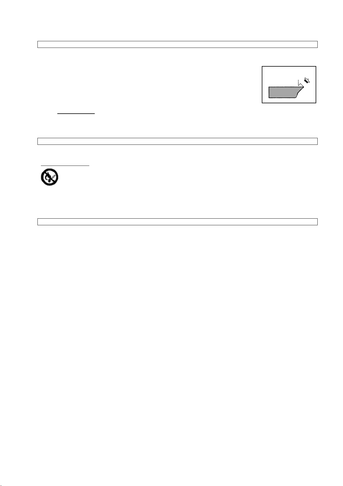
Use of Generator „Turning On“
Fig. 6
•Open the petrol cock by turning (ON).
•Put the choke in the starting position (see sign on the
air filter).
•Pull the starting cable slowly until resistance is felt,
then make a strong pull to start the engine.
•When the engine gets heated up, push the choke in
the initial position and wait for the indicator to light up.
•Connect the appliance cable
•If the output is overloaded, the overloading fuse will trip. The
indicator lights on.
•The generator will switch off automatically at short circuit.
Generator Turning Off
Fig. 7
•Make sure that NO appliance is connected.
•Put the on/off switch in OFF position.
•Turn the fuel cock to OFF.
Operator Safety Instructions
See General Safety Instructions and Initial Operation Safety Instructions.
•Do not use the machine until you have read the instruction manual carefully.
•Observe any safety instructions included In the manual.
•Be responsible to the others
Troubles – Causes – Troubleshooting
Trouble Cause Troubleshooting
The engine will not
start up .
1. Fuel cock closed
2. No fuel
3. The starter pull too weak
4. The ignition plug too distant
Ignition plug socket loose, wet
5. Ignition plug socket loose
6. Too little oil in the tank
1. Make sure that the fuel cock on/off
switch are in on position
2. Make sure that there is enough fuel in
the tank.
3. Pull the starting cable stronger.
4. Make sure that the ignition plug is
properly mounted.
5. Make sure that the ignition plug cable is on the
plug. Clean the plug and check the electrode
distance.
6. Replenish the oil
Engine runs unevenly
1. Too small appliance
Ignition system not in order
2. Poor fuel
1. Make sure that the plug is properly
mounted. Make sure that the plug cable
is on the plug. Clean the plug and check
the electrode distance.
2. Make sure that the used fuel is correct.
No current from
generator.
•Short circuit
•Defective cable
•Loose cable
1. If the light indicator is off, the defect is
impossible to be cleared by yourself. .
If the light indicator is on :
2. Press the overloading protection for the
required output.
3. Check the connection
4. Check whether a short circuit or overloading is not
the cause.
Inspections and Maintenance
Regular cleaning and maintenance is essential for perfect functioning and long service life of the unit.
No smoking in the course of the described jobs.
Never work close to sparks, flames or open fire.
16

Air Filter
•The air filter should be cleaned every 50 hrs of operation
•Loosen 2 hexagon-head screws.
•Remove the cover.
•Remove the air filter.
•Clean the filter with spirit or ethanol
•Drop a small amount of oil on the air filter and compress it.
•Put the filtration cartridge back and put the housing on.
Fuel Filter
•Remove the lid from the filler.
•Pull the fuel filer from the filler
•Clean the filter with spirit or ethanol
•Dry it with a soft cloth.
•Put the filter back in the filler.
•Replace the lid on the filler.
Ignition Plug
•Remove the ignition cable from the ignition plug (14) .
•Remove the plug using a plug wrench.
•Clean the electrode with a wire brush.
•Check the electrodes distance (0,7 - 0,8 mm correctly ) and adjust if necessary
•Put the place back in the place.
Oil Replacement
•Let the engine heat up.
•Unscrew the filler plug.
•Remove the discharge screw and drain the used oil onto a suitable container. .
•Check packing and replace it if necessary. Screw the discharge screw in a pour new oil in. (For the kind of oil see Chapter 4).
•Screw the filler neck on.
Noise Silence Check
•Let the noise silencer cool down.
•The silencer could be clogged with parts of the filter.
•Unscrew the lid and remove the cover.
•Clean the surface with a wire brush.
•Replace if necessary.
Inspections and Maintenance Safety Instructions
The unit will serve as a sufficient aid only if maintained and cared for appropriately. Insufficient maintenance and care may result in
accidents and injuries.
Inspections and Maintenance Schedule
Time interval Description Other details if necessary
Every 3 months •Check the ignition plug condition, adjust distance and clean it
Before each use •Check the engine oil level
After 1 month and
after 6 months •Replace engine oil
Every 3 months/50
hours of operation •Clean the air filter or replace it if necessary
Every 6 months •Clean the petrol cock and filter, replace if necessary
Every 12 months •Check the valves distance, adjust if necessary . With the engine cooled down
Before each use •Check the petrol hose for cracks and other damages, replace if
necessary.
Before each use •Check the exhaust system for holes, pack or replace as necessary
Before each use •Check the noise silencer, clean or replace as necessary
Before each use •Check the correct function of the choke
Every 12 months •Check the cooling fan
Before each use •Check the Bowden starting cable, replace if necessary
Every 6 months •Check screws and connecting elements and replace if necessary.
Fig. 10
17
Other manuals for GSE 4700 RS
1
Table of contents
Other Gude Portable Generator manuals

Gude
Gude GSE 5500 DSG Wiring diagram

Gude
Gude GSE 950 User manual

Gude
Gude ISG 1200-1 User manual

Gude
Gude GSE 5500 DSG User manual

Gude
Gude GSE 4701 RS User manual

Gude
Gude GSE 951 User manual

Gude
Gude GSE 6701 RS User manual

Gude
Gude GSE 950 User manual

Gude
Gude GSE 2501 User manual

Gude
Gude GSE 8701 RS User manual
Popular Portable Generator manuals by other brands

Rohde & Schwarz
Rohde & Schwarz HMF2525 user manual

EUROM
EUROM Independ-2500 instruction manual

Datalogic
Datalogic PWR-240 installation manual

Xtreme Power
Xtreme Power 65038 Owner's manual and safety instructions

Champion Power Equipment
Champion Power Equipment C42412-1 manual

Predator
Predator 59135 user manual