Guhring GISS 2000 User manual

GISS 2000
Operating Manual

GISS 2000 Operating Manual
2
Inhaltsverzeichnis
Contents
Introduction .........................................................................................................................................3
Symbols and pictographs ..................................................................................................................3
1.) Safety ..............................................................................................................................................4
1.1 Danger potential of the equipment ......................................................................................4
1.2 Safety notes............................................................................................................................4
1.3 Correct application.................................................................................................................5
1.4 Work area requirements........................................................................................................5
1.5 Authorised operators.............................................................................................................6
2.) Shipping and packaging................................................................................................................6
2.1 Delivery ...................................................................................................................................6
2.2 Unpacking...............................................................................................................................6
3.) Decription of equipment ...............................................................................................................7
3.1 Functional description ...........................................................................................................7
3.2 Types.......................................................................................................................................7
3.3 Dynamic output regulator ....................................................................................................8
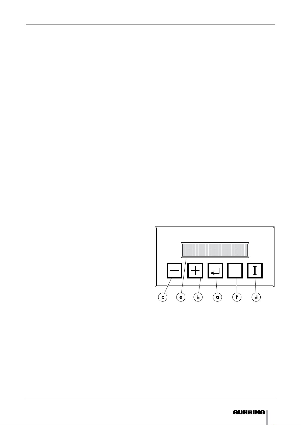
3.4 Key pad and display...............................................................................................................8
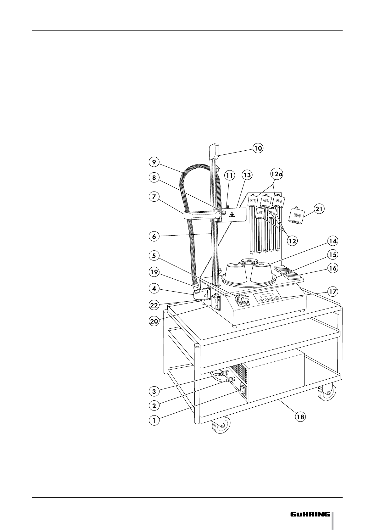
3.5 System summary...................................................................................................................9
4.) Commissioning and operation ...................................................................................................10
4.1 Electrical connection...........................................................................................................10
4.1.1 GISS 2000 .......................................................................................................................10
4.1.2 SPEED-COOLER ............................................................................................................. 11
4.2 Installation and assembly ...................................................................................................12
4.2.1 GISS 2000.......................................................................................................................12
4.2.2 SPEED-COOLER (optional) ...........................................................................................14
4.2.3 Inserting the adaptors...................................................................................................15
4.2.4 Speed Cooler Manager.................................................................................................16
4.3 Switching-on the equipment ..............................................................................................17
4.4 Menu guide..........................................................................................................................17
4.4.1 Shrink fit menu ............................................................................................................19
4.4.2 Setting the heating time .............................................................................................20
4.4.3 Setting the language ..................................................................................................21
4.4.4 Setting the dimensional system ...............................................................................22
4.4.5 Selecting the operating type .....................................................................................22
4.4.6 Retrieving company settings .....................................................................................23
4.5 Operating process ...............................................................................................................25
4.5.1 Suitable shrink fit chucks ............................................................................................25
4.5.2 Preparing the shrink fit chucks and tools...................................................................25
4.5.3 Heating the shrink fit chuck.........................................................................................26
4.5.4 Cooling the shrink fit chuck .........................................................................................29
4.6 Switching-off the equipment .............................................................................................30
4.7 GISS 2000 Trouble-shooting ...............................................................................................31
4.7.1 Error messages .............................................................................................................31
4.7.2 Other malfunctions.......................................................................................................31
4.8 SPEED-COOLER Troubleshooting ......................................................................................33
4.8.1 Venting the cooling system .........................................................................................34
4.8.2 Water pump not running .............................................................................................34
4.8.3 Condensation on dissipator ........................................................................................35
4.9 Important notes regarding the shrink fitting process......................................................35
5.) Cleaning ........................................................................................................................................36
5.1 Speed Cooler ........................................................................................................................36
5.2 GISS 2000 shrink fit system ................................................................................................36
6.) Maintenance and repairs ............................................................................................................37
6.1 Maintenance .........................................................................................................................37
6.2 Replacing the GISS 2000 fine-wire fuse ............................................................................37
7.) Technical data...............................................................................................................................38
8.) Replacement parts.......................................................................................................................39

GISS 2000 Operating Manual
3
Vorbemerkung
Introduction
With the purchase of GISS 2000 you have acquired an innovative and easy to operate
system for changing tools in shrink fit chucks.
Please read this operating manual carefully and observe the safety notices prior to
commissioning the system in order to ensure longevity and above all safe operation
of GISS 2000.
All personnel entrusted with operating the GISS 2000 shrink fit system must also be
familiar with and observe this operating manual prior to the initial operation.
Keep this operating manual readily available in order to ensure access to the informa-
tion at all times.
It is not permitted to photocopy, save on a computer system or forward extracts of this
operating manual without prior consent of Gühring oHG.
Gühring oHG reserves the right to undertake technical and visual changes at any time
without specific notification in the interest of further development. All dimensions, notes
and specifications in this operating manual are not covered by the warranty. Legal claims
based on the operating manual can subsequently not be exercised.
Gühring oHG Conditions of Sale andTerms of Payment apply.
Symbols and pictographs
Warning signs
General warnings of risk of danger to human life
or property are demonstrated with the following
symbols:
Warning of risk of danger through electric current
or electric shock respectively:
Warning of a specific danger. Pictograph with a
rectangular border, standing on a corner:
Mandatory signs
Mandatory signs are round, light pictograph on
dark background:

GISS 2000 Operating Manual
4
Sicherheit
1.) Safety
1.1 Danger
The GISS 2000 shrink fit system has been manufactured in accordance with the latest
technologies and safety regulations. Function and safety tests have been carried out.
However, the system can be a source of danger if not operated by trained or at least
instructed personnel. The same applies to inappropriate or incorrect use of the GISS
2000 system.
If this operating manual is not observed there is the risk of the following
•electricshock,•healthhazards,•damagetotheequipment.1.2 Safety notes
•TheGISS2000shrinktsystemandtheSPEEDCOOLER(coolingunit)mustonlybe operated with the correct mains supply voltage.
It is paramount to check the specification plate.
•Themainsplugmustonlybepluggedintoasocketwithanearthingcontact!Theprotective capacity must not be eliminated by the use of an un-earthed extension
lead.
Disconnection of the earthing wire inside or outside of the equipment is dangerous
and prohibited.
•Theequipmentmustonlybeoperatedifinperfectcondition.Ifoneoftheunitsisdamaged, the system must no longer be used.
•Duetotheprocess,theshrinktchuckbecomesveryhotinlocalisedareas.Thereis an acute danger of burning if these areas are touched.The equipment has been
designed so the hot shrink fit chuck does not need to be removed, thus, it should
always be left in the holder until it has cooled down.
•Alwayswearprotectivegloveswhenhandlingtheshrinktchucksandthetools.The gloves protect against cuts from the sharp edges of the tools. In addition, they
provide protection against burns from the hot areas of the shrink fit chucks.
•Theshrinktsystemoperatesusingahighfrequency.Subsequently,apersonwitha heart pace maker must not operate the equipment. During the operation of the
shrink fit system such persons must also observe a minimum safety distance of 1
metre to the equipment.
•Undernocircumstancesmustmetalobjectscomeintothesphereoftheinductionspindle.They would heat up intensively when the shrink fit system is operated.This
appliesespeciallytojewellery,i.e.aringonangerorachain,asthereisanacutedanger of burning
•Theshrinktsystemmustnotbeoperatedwithoutaninductorlimitstopcollar.Amissing or incorrect inductor limit stop collar can result in scatter fields exiting the
spindle area. If the aforementioned is not observed, it may cause a risk to the opera-
tor and damage to the equipment or tools respectively.

GISS 2000 Operating Manual
5
•Theequipmentmustbedisconnectedfromthemainssupplypriortoanycleaning,maintenance or repair work being carried out.The same applies if the equipment is
not used for prolonged periods.
•Duringcleaning,liquidmustnotbeallowedtoenterinsidethehousing.Protectthesystem against moisture. Risk of electric shock.
•Positionthepowersupplycablesinsuchawayastopreventanybodytrippingoveror getting caught up in them.
•RepairstotheGISS2000shrinktsystemmustonlybecarriedoutbyqualiedpersonnel. Electrical work on the equipment must only be carried out by a qualified
electrician.The opening of the housing by unauthorised personnel is prohibited.
Attention! Dangerous residual voltage may be present in the housing up to 5 min-
utes after turning off the equipment.
•Nodissassemblyofsafetydevices.Thedissassembly,by-passingorclosingdownof safety devices is prohibited.
1.3 Correct application
The GISS 2000 shrink fit system has been designed and developed especially for the
tool change in shrink fit chucks.The system is suitable for shrink fitting HSS tools with a
shank-Ø from 6 to 32 mm and carbide tools with a shank- Ø from 3 to 32 mm.
With the aid of a chuck adapter system all standard taper size shrink fit chucks can be
applied. In addition, the coolant body adapter system enables the cooling of chucks with
any outer contour.
The system is only intended for industrial applications.
Gühring oHG cannot accept liability for applications not described in this operating
manual. Equally, such actions forfeit any claims made under warranty.
1.4 Work place requirements
Keep the workplace tidy and clean. Untidiness at the workplace increases the danger
of an accident.
The equipment must be positioned on a sufficiently rigid and level substructure. During
operation it must not be exposed to impact or be tilted.
The system must be protected against moisture and contamination.
Sicherheit

GISS 2000 Operating Manual
6
1.5 Authorised operators
The GISS 2000 shrink fit system must only be operated by authorised and trained per-
sonnel.
The operator is responsible for third parties in the work place.
The owner must
•instructtheoperatorregardinghistasks,•maketheoperatingmanualavailabletotheoperator•ensurethattheoperatorhasreadandunderstoodthemanual.2.) Shipping and packaging
2.1 Delivery
The GISS 2000 shrink fit system is despatched suitably packaged to ensure that, under
regular shipping conditions, it reaches its point of destination undamaged.
Note:
The carrier is liable for any damage that occurs during transportation. If damage to the
packaging is visible and there is reason to believe that the contents are damaged, im-
mediately contact the carrier regarding the claim for damages.
Transportation and storage should be performed under normal conditions, i. e. at tem-
peratures between +5°C and +70°C and a relative humidity of maximum 80%.
Attention!
The system may be permanently damaged if stored or transported under pro-
hibited conditions. It is possible that the damage is not visible externally.
Inthiscase,themanufacturerdoesnotacceptthewarrantyandtheliabilityforconse-
quential damages.
2.2 Unpacking
Remove all packaging and take out the system including the accessories.
Ensure that all the components of the GISS 2000 shrink fit system are included in accord-
ance with the delivery note and the accompanying documents and are undamaged.
Compare the data on the type plates to that on the delivery note and your order docu-
ments.
If you do not require the packaging for further use, i. e. for the return of the system for
repairs, please dispose of it in an environmentally friendly way.

GISS 2000 Operating Manual
7
Beschreibung des Gerätes
3.) Description of equipment
3.1 Function principle
The GISS 2000 shrink fit system’s function principle is an induction spindle, also called an
inductor. The inductor is a current-carrying spindle that produces a magnetic alternating
eld.Whenaferrousmetalobjectisinsidethespindleitisheatedup.Thefrequencyofthealternatingeldissetsothemetalobject,inthiscaseashrinktchuck, only heats up near the surface. The generation of heat in the shrink fit chuck is
continued by GISS 2000 until it is possible to manually remove or insert the tool, the
time required is approximately 5 seconds.
This is achieved before the tool itself becomes hot. At this point, heat has only generated
on the surface of the shrink fit chuck, as there has been insufficient time for the heat to
penetrate.This way, only a relatively small amount of energy is supplied or consumed
respectively. It is, therefore, possible to keep the subsequent cooling phase very short.
Cooling is achieved via water-cooling. The cooling power is provided by the SPEED-
COOLER. The cooling water permanently circulates through the cooling body. The hot
shrink fit chuck remains in its holder and is rotated into the cooling position via the
turntable.The water-cooled cooling body is then positioned over it. The cooling power
is transferred by direct contact with the shrink fit chuck. After a short time the shrink fit
chuck can be touched again.
The GISS 2000 shrink fit system is designed to carry out a continuous tool change (thanks
to the simple adapter system all standard shrink fit chucks can be used).
The GISS 2000 shrink fit system‘s design and operation allow a very quick tool change
to be carried out. Subsequently, the shrink fit chucks have a long tool life as they only
become hot in localised areas and, in addition, further contact is only necessary after
they have cooled down again.
Therefore, a simple and safe operation is ensured.
3.2 Versions
GISS 2000 Eco
GISS 2000 Eco is the cost-efficient entry level version into shrink fitting. This version
already incorporates the powerful electronics and the easy software for carbide and
high speed steel tools up to Ø 32 mm. It includes a shrink fitting station but not a cool-
ing unit.
GISS 2000 Eco Plus
The GISS 2000 Eco Plus shrink fit system also includes a cooling unit and cool-
ing body to enable a fast cooling down of the shrink fit chucks.
The GISS 2000 Eco version can be up-graded to the GISS 2000 Eco Plus version using
a special upgrade kit.
GISS 2000 Comfort
The GISS 2000 Comfort is the fully equipped version for an efficient operation. In addi-
tion to a cooling facility, this version also includes a turn table with three shrink fitting
stations.

GISS 2000 Operating Manual
8
This makes a continuous operation possible without interruption.
The GISS 2000 Eco Plus system can be up-graded to the comfort version using an up-
grade kit.
GISS 2000 Comfort Plus (special)
The GISS 2000 Comfort Plus is the universal solution for the shrink fitting of tools. Its
special electronics offers twice the performance in comparison to the other models.With
an additional inductor, it is possible to shrink fit for insertion and withdrawal carbide and
high speed steel tools up to Ø 50 mm. A cooling unit and a turntable with three shrink fit
stations are part of the standard equipment. It is not possible to up-grade the standard
versions to the Comfort Plus model.
3.3 Dynamic output control
Dependingonthelocalpowersupply,thevoltageinthenetworkmaybesubjectedtoheavy fluctuations.This also has an effect on the heating capacity of the GISS 2000 shrink
fit system. With a reduced voltage supply, the heating capacity may not be sufficient to
heat-up the holders quickly. If the voltage increases, there is the danger of the holders
over-heating.
The GISS 2000 shrink fit system solves this problems with dynamic output control.The
heating capacity is determined and controlled during the entire shrink fit process.
The intermediate circuit voltage is displayed during the shrink fit process, it should not
fall by more than 35 Volts prior to the shrink fit process.
This ensures that optimal results are achieved under all operating conditions.
3.4 Keypanel and display
a Enter / confirm key
b Plus key
for increasing the tool-Ø
c Minus key
for reducing the tool-Ø
d Inductor start key
e LCD display
f ESC-key
ESC
Beschreibung des Gerätes

GISS 2000 Operating Manual
9
3.5 System summary
Beschreibung des Gerätes
1 Mains switch
SPEED-COOLER
2 Coolant hose return
3 Coolant hose
4 Inductor plug-in connection
Ø 3 - 32 mm
5 Mains switch GISS 2000
6 Inductor linear unit
7 Handle with brake
8 Inductor start key
9 Inductor energy supply hose
10 Drawspring
11 Equipment-on indicator
lamp
12 Cooling bodies
12a Cooling bodies with inter-
change lock
13 Inductor
14 Shrink fit chuck adapter
15 Turntable
16 Tool depository
17 Keypanel and display
18 Trolley (option)
19 Fine-wire fuse for
electronic control
20 Plug-type connector for
inductor Ø 40 - 50 mm
optional
21 Cooling body Ø 40 - 50 mm
optional
22 Plug-type connector for
SPEED-COOLER control line
optional
ESC

GISS 2000 Operating Manual
10
4.) Commissioning and operation
In the following, the required procedures are
described in the correct sequence for commissioning
the GISS 2000 shrink fit system. Operating the
system is relatively simple. However, you should
familiarise yourself with the equipment prior to
working with it.
Incorrect operation can be dangerous for the opera-
toranddamagetheequipment,inparticularthereis the danger of the shrink fit chuck overheating.
4.1 Electrical connection
If the GISS 2000 shrink fit system or the SPEED-
COOLER have not been supplied with the correct
plug, a suitable plug must be fitted.
Important:The above must be carried out by a quali-
fied electrician.
4.1.1 GISS 2000
The electrical connection is 4-pole. Connect the 3-
phases and earth. The connection to earth is com-
pulsory to comply with electrical safety regulations.
Neutralisnotconnected.Therotaryeldofthe3phases does not need to be observed.
Please ensure:
•Theelectricalconnection(socket-outlet)withthe customer must have a connected earthing
contact.
•Iftheplugisreplaced,theearthisconnectedtothe green/yellow wire.
•Thepowersupplymustcorrespondwiththedataon the type plate.
•Dependingonthedistancetothemaindistribu-
tion, the conductor cross-section of the custom-
er‘s electrical connection should be chosen gen-
erously. Furthermore, no additional equipment
should be connected to this supply line. If the
above is not observed, the voltage level may drop
too much during the shrink fit process resulting
in the necessary shrink fitting output not being
achieved.
Customer fuse protection:
GISS 2000 Eco, Eco Plus, Comfort: 3 x 16 Ampere
GISS 2000 Comfort Plus (special): 3 x 32 Ampere
Inbetriebnahme und Bedienung

GISS 2000 Operating Manual
11
•Ifconnectedviaatransformer,itmustbecheckedthat there is a continuous earth connection from
the equipment plug to the voltage connection
on-site with the customer..
Attention! Under no circumstances must the sys-
tem be operated with a higher rating fuse protec-
tion.
4.1.2 SPEED-COOLER
The voltage connection must be 3-pole. Live, neu-
tral and earth must be connected. The connection
to earth is compulsory to comply with electrical
safety regulations.
Please ensure:
•Thepowersupplymustcorrespondwiththedataon the specification plate.
•Theelectricalconnection(socket-outlet)withthe customer must have a connected earthing
contact.
•Whenusingadapterplugsextremecareshouldbe taken to ensure that the earthing contact is
continuous to the socket. Often with adapters
the earthing is not continuous.
•Iftheplugisreplaced,theearthisconnectedtothe green/yellow wire.
•Customerfuseprotection:10 Ampere
•Ifconnectedviaatransformer,itmustbeensuredthere is a continuous earth connection from the
equipment plug to the voltage connection on-site
with the customer.
Inbetriebnahme und Bedienung
Earth
yellow/green

GISS 2000 Operating Manual
12
4.2 Location and assembly
The GISS 2000 system and the SPEED-COOLER must
be positioned on sufficiently rigid level ground.
During operation the equipment must not be posi-
tioned at an angle, be tilted or exposed to impact
and vibration..
4.2.1 GISS 2000
Space required:
Distance to the wall:
GISS 2000 Eco L = 0
GISS 2000 Eco Plus
GISS 2000 Comfort L = 150
Optimal table height for all versions: H = approx.
800 mm
GISS 2000 is to a large extent pre-assembled. It is
only necessary to fit and align the linear unit (6) onto
the housing with the screws provided.
Important: For safety reasons an electrically con-
ductive contact must exist between the linear unit
andthehousing.Therefore,thelinearunitmustbefitted very carefully.
•Unscrewthefourscrews(22).GISS 2000 Economic and Economic Plus (without
turntable):
The supplied contact springs (24) must be
inserted between the base plate and the housing.
The springs are situated under the retaining plate
(25), that is screwed to the housing.The retaining
plate (25) serves only for protection of the contact
springs (24) during transportation and can be
removed.
GISS 2000 Comfort and Comfort Plus (with
turntable):
The four tooth lock washers (23) must be inserted
between the screwhead and the base plate.
•Positionthelinearunit(6)togetherwiththebaseplate.
•Screw-inthescrews(22)andtightenlightly
Inbetriebnahme und Bedienung

GISS 2000 Operating Manual
13
•Mounttheinductor(13)intotheholderofthelinear guide. Ensure the locking bolt (19) is en-
gaged.
•Positionashrinktadapter(14)ontotheturnta-
ble (15).
•Insertasuitableshrinktchuck(21)intotheadapter (14.
•Insertthelimitstopwasher(20)correspondingwith the diameter of the selected shrink fit chuck
into the inductor (13).
•Alignthelinearunit(6)sotheinductor(13)iscen-
tred over the chuck (21).Tighten the four screws
(22).
•Connecttheinductorplug(4)tothehousingOnly applies to GISS 2000 Komfort Plus:
The two inductors have different plugs, eliminating
a mix-up of the plugs.The plug-type connectors on
the GISS 2000 Profi Plus are arranged so only one
of the connectors can be opened.This prevents both
inductors being connected at the same time
Inbetriebnahme und Bedienung

GISS 2000 Operating Manual
14
4.2.2 SPEED-COOLER (option)
Space required:
Important!
The SPEED-COOLER uses ambient air to cool the
water in the cooling circuit. It must be ensured that
there is sufficient free space for the air to circulate
(see top view). Otherwise the cooling output will
be insufficient.
•PositiontheSPEED-COOLERonasufcientlyrigid and level substructure alongside or below
the GISS 2000 system.
•FilltheSPEED-COOLERwithamixtureoftap water and anti-freeze (e.g. commercial
automotive anti-freeze).
Mixture ratio water : anti-freeze = 2 : 1
Generally, new systems are already filled with
anti-freeze. All that is then required is to add tap
water to the cooler. The system is filled via the
screw-type cap situated on the upper side. The
cooling spiral in the water reservoir must be
completely covered.
•BleedingtheSPEED-COOLER:
Connect the nipple with the hose piece (1) (sup-
plied) to the flow pipe (3) of the SPEED-COOLER.
Do not turn the SPEED COOLER on. The pump
could be damaged if run dry. After a short time
water will run out of the pipe. Remove the nipple
with the hose.
•Bleedingthecoolingcircuit:
Connect one of the GISS 2000 system‘s two
circulation hoses of to the flow pipe (3) of
the SPEED-COOLER. Connection is via quick
release couplings. The circulation hoses are
interchangeable (the direction of circulation in the
cooling bodies (12) is not important).
Connect the mains cable of the SPEED-COOLER.
Ensure the supply voltage corresponds with that
on the type plate of the SPEED-COOLER.
GISS 2000 Comfort Plus only:
Connect the control line of the SPEED-COOLER
to the connector (22) of the GISS 2000 system.
Turn-on the GISS 2000 system at the mains
switch (5).
Turn-on the SPEED-COOLER. Water is now
pumped into the cooling system forcing the air
to vent from the hoses and the cooling bodies.
Inbetriebnahme und Bedienung
Front view
Top view

GISS 2000 Operating Manual
15
Wait unil water exits the open hose, then con-
nect the hose to the return (2) of the SPEED-
COOLER.
Switch-off the SPEED-COOLER.
GISS 2000 Comfort Plus:Turn-off the GISS 2000
system at the mains switch (5).The mains switch
of the SPEED-COOLER remains on. The SPEED-
COOLER is automatically turned on and off by
the GISS 2000 system.
Top up the SPEED-COOLER with tap water
(drinking water). The cooling spiral in the water
reservoir must be completely covered.
Note: To ensure perfect functioning of the re-cooling
plant,thensoftheair-cooledcondensatormustbe kept clean. Particularly if the ambient air is of a
highoilanddustcontent,thensofthecondensercan become excessively soiled. Regular cleaning
isnecessary,asdescribedinchapter5.Atrolleyisavailable as an option which is optimally suited for
positioning and setting-up the two systems (see
system summary)..
4.2.3 Inserting the adapters
The adapter system consists of shrink fit chuck
adapter (14) and the inductor limit stop washer (20).
The purpose of the inductor limit stop washer (20)
is the correct positioning of the inductor above the
shrink fit chuck (21). Furthermore, the limit stop
washer controls the magnetic alternating field (20),
preventing the tool from heating up and providing
an upwards shield for the alternating field.
The correct adapter system must be used for each
shrink fit chuck size.
Not observing the above can lead to dangerous
situations for the operator and to equipment or tool
damage.The application of an incorrect inductor limit
stop washer (20) can result in stray fields exiting
the spindle area.The shrink fit system must not be
operated without an inductor limit stop washer
(20).
Sectional limit stop washers (optional) can be applied
for tools possessing a larger cutting edge diameter
than the shank diameter (i.e.T-slot drills).
Shrink fit chuck adapters (14)
The shrink fit chuck adapters (14) are marked with
the holder taper size.
•Insertthecorrectshrinktchuckadapter(14)intothe turntable (15) from above.

GISS 2000 Operating Manual
16
Inductor limit stop washer (20)
The inductor limit stop washer (20) is inserted
manually (without tool key).The inductor limit stop
washer(20)isdesignedwithabajonettting.•Selectthecorrectinductorlimitstopwasher(20)for the respective tool.
•Inserttheinductorlimitstopwasher(20)intotheinductor from above.The red dot on the inductor
limit stop washer (20) must be aligned with the
red dot on the inductor housing.
•Insertindexngerandmiddlengerintotherecesses of the inductor limit stop washer (20)
and rotate clockwise until it engages. A spring
element snaps into a notch of the inductor limit
stop washer (20).
The shrink fit system is now prepared and ready for
the tool change of a specific shrink fit chuck.
4.2.4 Speed-Cooler Manager
The cooling manager (Guhring no.: 4759 code 1,000)
automatically switches the SPEED-COOLER on and
off.This prevents forgetting to switch-on the cooler or
the cooler running constantly, protecting the cooler
and minimising maintenance costs. See separate
assembly instructions.
Inbetriebnahme und Bedienung

GISS 2000 Operating Manual
17
4.3 Turning-on the equipment
Connect to the mains supply. Ensure that the mains
voltage corresponds with that on the specification
plate. If yes, plug-in the mains plug.
•ConnectthemainscableoftheSPEED-COOLER.Mains supply fuse protection: 10 Ampere.
•ConnectthemainscableoftheGISS2000sys-
tem. Mains supply fuse protection:
GISS 2000 Eco,
Eco Plus, Comfort: 3 x 16 A
GISS 2000 Comfort Plus (special): 3 x 32 A
Attention! Under no circumstances must the
systems be operated with a fuse protection of a
higher rating.
•Turn-ontheSPEED-COOLERatthemainsswitch(1).The circulation pump will start operating.
The SPEED-COOLER does not require a warming-up
period. Immediately after switching-on the SPEED-
COOLER you can begin with the first tool change.
•Turn-ontheGISS2000systematthemainsswitch(5).
•WhenapplyingtheSpeedCoolerManager,theSpeed Cooler is switched-on when the induction
spindle is activated.
Attention!The electronics of the GISS 2000 Comfort
Plus system must be cooled by the SPEED-COOLER
to prevent over-heating. A temperature controller will
otherwise turn-off the system after a short time and
only release the system again after a cooling down
period.Therefore,GISS2000ProPlusmustonlybeoperated when the SPEED-COOLER is turned-on.
4.4 Menu guide
After switching-on, you enter the shrink fit menu.
Here, you can select the type and the size of the
shrink fit chuck and start the shrink fit process.
Different setting possibilities are available in
sub-menus.
•+ - keys - simultaneously -
branch into sub-menu
•-key to previous menu point
•+key to next menu point
•key select menu point
•ESC key return to overriding menu,
without saving
•Ikey confirm and save
Inbetriebnahme und Bedienung
ESC

GISS 2000 Operating Manual
18
Overall menu
Schrumpfmenü
Anzeige
Schrumpffutter
Auswahl
voriges Futter
aus Liste
Auswahl
nächstes Futter
aus Liste
Auswahl
nächstes Gruppe
aus Liste
Anzeige der
Schrumpf-
parameter
Schrumpfvorgang
mit Anzeige
der Daten
Heizzeit
verändern
Heizzeit
Sprachen
Maßsystem
Betriebsarten
Werkseinstellung
Taste -
Taste +
Taste + / -
Taste + / -
Taste + / -
Taste + / -
Taste + / -
Tasten - +
gleichzeitig
Taste
Starttaste
oder Taste I
Taste ESC
Taste ESC
Taste ESC
Taste ESC
Taste ESC
Taste
Sprache
auswählen
Taste
Maßsystem
auswählen
Taste
Betriebsarten
wählen
Taste
Rücksetzen
auf Werks-
einstellungen
Taste
Tasten - +
gleichzeitig
Shrink Fit Menu
Display
Shrink Fit Cucks
Select
previous chuck
from list
- key
+ key
Select
next chuck
from list
Select
next group
from list
+ - keys
simultaneously
key
start key
or Ikey
Display
shrink t parameters
Shrink t process
with data display
+ - keys
simultaneously
Heating time
Language
key
ESC key
Modify
heating time
key Select
language
ESC key
+ / - key
+ / - key
+ / - key
System of
measurement
Operating type
Select system
of measurement
+ / - key key
ESC key
ESC key
+ / - key key
key
Select
operating type
ESC key
Return to
manufacturer‘s
settings
Manufacturer‘s
settings

GISS 2000 Operating Manual
19
4.4.1 Shrink fit menu
The display always shows the currently set shrink fit chuck.
Standard
Ø 10 - 12
Spule Pos. #4
Typ des
Schrumpffutters
Einstellung
der Spule
Größe des
Schrumpffutters
•–keytopreviouschuck•+keytonextchuck•+–keystonextchucktypesimultaneously
•pressanddisplaysshrinktparameters
hold key
Parameter
7,0 kHz
545 E
525 V
4.5 s
450 r
23 °C
Max. Heizzeit
Temperatur
Elektronik
Frequenz
Spannung in
Zwischenkreis
•STARTkeystartingtheshrinktprocess
or I
*onlyforspecialspindlewithadjustmentpossibility*
Type of shrink
t chuck
Size of shrink t
chuck
Spindle setting
Frequency Max. heating time
Intermediate
circuit voltage
Electronics tem-
perature
Parameters
Spindle

GISS 2000 Operating Manual
20
4.4.2 Setting the heating time
Heizzeit Zurück ins
Schrumpfmenü
Auswahl
voriges / nächstes
Futter aus Liste
Auswahl
nächste Gruppe
aus Liste
Zurück ohne
speichern
Standard
Ø 10 - 12
Heizzeit
0 - 60: 4.5 s
Anzeige der Heizzeit
für das eingestellte Futter
Markierung blinkt
Zeit kann verändert werden
im angegebenen Bereich
Standard
Ø 10 - 12
Heizzeit
0 - 60: 4.5 s
Zahlenwert ändern
Speichern
und zurück
Taste + / -
Tasten - / +
Taste ESC
Zurück ohne
speichern
Taste ESC
Taste ESC
Taste
Taste
Taste
Taste ESC
Tasten - / +
gleichzeitig
Standard
Ø 10 - 12
Heizzeit
0 - 60: 4.5 s
Typ des
Schrumpffutters
Eingestellter WertEinstellbereich
Größe des
Schrumpffutters
•–/+keytoprevious/nextchuck•+–keytonextchucktype
simultaneously
•key set value is marked by a flashing *. Value may
now be changed.
Displaying max. heating time of current chuck
Heating time ESC key
key
ESC key
Heating time
Return to
shrink t menu
Select
previous / next
chuck from list
+ / - key
+ / - keys
simultaneously
Heating time
key
Select
next group
from list
Display of heating time
for set chuck
* marker ashing
time can be modied
for range specied
ESC key Back w/o
saving
key
+ /- key
ESC key Back w/o
saving
Modifying
numerical value
Save and back
Heating time
Type of shrink
t chuck
Size of shrink t
chuck
Setting range Set value
Table of contents
Popular Industrial Equipment manuals by other brands

MICRO-EPSILON
MICRO-EPSILON ELTROTEC Endolight FOT LED instruction manual

Timberwolf
Timberwolf TW-C12 Operator's manual

ABB
ABB HT564330 Operation manual

SEM
SEM 3000 Operation and maintenance manual

Siemens
Siemens MICROMASTER 440 Getting started guide

ABB
ABB OVR-15 Instruction, Operation and Maintenance Manual