Guide Gear 225039 User manual

PACKAGE CONTENTS
Part Description Quantity
A Top Connector (with PVC Tubes) 1 (4)
B Upper Ribs 4
C Middle Ribs (with PVC Tubes) 8 (8)
D1 & D2 Mounting Bar with spring locks 2
E1 & E2 Mounting Bar Extension
w/spring locks
2
F Cab Skin 1
G Lock Nut, 5/16"- 18 8
H U-bolt, 5/16"- 18, 2- 3/16" x 3" 4
I Back Mounting Plate 2
J Front Mounting Plate 2
WARNINGS AND CAUTIONS
WARNING
• ThecabwillNOTprotectagainstnoise,engineexhaust,chemicals,collision,roll-overorotheraccidents.
• Followallyoursnowthrowermanufacturersrecommendedsafetyinstructions.
• Operatingasnowthrowerwiththiscabwillrestrictyoureldofvision.Watchcarefullyforpeople,children,
obstructions or obstacles
• Thecabaddsheighttoyoursnowthrowersowatchcarefullyfortreelimbsorotheritemsoverheadthatyou
couldpreviouslygounderwithoutacab.
CAUTION
• Periodicallycheckallboltstoseethattheyaretight.Ifoneormoreboltscomeloose,failureofcabpartsmayoccur.
A
C
B
D1 & D2
E1 & E2
F
G
H
I
J
12cH56_13062
225039
SNOW THROWER CAB
For assistance with this product, please call The Sportsman’s Guide Customer Service toll free at:
800-888-5222, 7AM - 7PM CST, Monday - Friday or email us at: custserv@sportsmansguide.com

2
PREPARATION
Beforebeginningassemblyofproduct,makesureallpartsarepresent.Comparepartswithpackagecontents
listanddiagramabove.Ifanypartismissingordamaged,donotattempttoassemble,installoroperatethe
product.Contactcustomerserviceforreplacementparts.
Estimated Assembly Time:30minutes
Tools Required for Assembly:
•Onetapemeasure •Adjustablewrench
And either (your choice):
•1/2"wrenchordeepsocketoranotheradjustablewrench
ASSEMBLY INSTRUCTIONS
Step 1: ASSEMBLE THE MOUNTING BAR
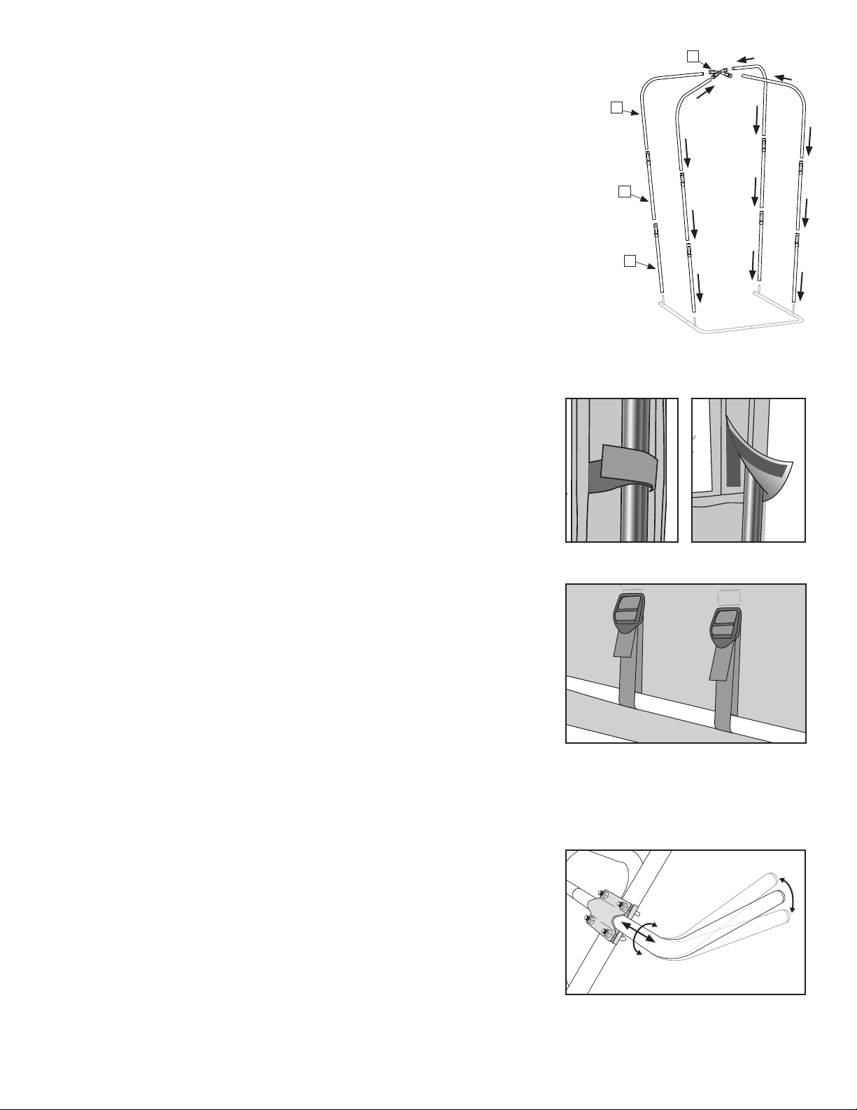
Startbyinsertingthemountingbars[D1&D2]intoeachother.The ends of the
tubes that go together on the mounting bar and the mounting bar
extensions are labeled “A”, “B” or “C”. Match the letters (A to A, B to B,
etc.) and insert the male (tapered) end into the female (non-tapered)
end, matching up the spring lock on the male end with the hole in the
female end.(Fig.1)
Next,insertthemountingbarextensions[E1&E2]intoeachopenendofthe
mountingbar.Matchupthespringlocksonthemountingbarextensionswiththe
holesonthemountingbars.(Fig.1)
Fig. 1
D1 & D2
E1 & E2
Correct Incorrect
Fig. 2
Correctnal
assembly(back)
Correctnal
assembly(front)
Fig. 3
Step 2: ATTACH MOUNTING BAR TO THE SNOW THROWER HANDLEBAR
Theassembledmountingbar[D1-D2&E1-E2]mountstothehandlebarsofyour
machinewithanadjustableU-boltsystemdesignedtotavarietyofdifferent
machines.
Thebarsmustbemountedonyourmachineinawaythatwillnotinterferewith
itsoperation,controls,lightsormovingparts.
Thepreferredmountinglocationforthehorizontalmountingbarsisonthe
front(motorside)ofthehandlebars.Howeveryoumayneedtomountthebarson
thebackofthehandlebar.
Themountingbarshouldbeplacedonthehandlebarsaminimumof24"anda
maximumof30"fromtheground(asmeasuredfromthebarend).Thiswillallow
headroomofatleast6.5'inthepeakofthecabroof.
Pleaseseethediagramsbelowforcorrectandincorrectinstallationofthe
mountingplates[I&J]whenattachingmountingbartothehandlebars.(Fig.2)
Whileholdingtheassembledmountingbarsinahorizontalpositionatthe
correctheight,slidetwoU-bolts[H]fromthebacksideofthesnowthrower(not
themotorside)throughthebackmountingplate[I]andthefrontmountingplate
[J]positionedonthefrontside.(Fig.3)Threadfour5/16"-18locknuts[G]onto
thefourU-boltstudandtightenslightly.Repeatontheotherhandlebarupright.
AfterallfourU-boltsareinstalledandalleightnutsarethreaded,setthemounting
bartoahorizontalpositionandfullytightenalleightnuts.
J
I
I
J
G
GJ
H
I

3
Step 3: ASSEMBLE THE CAB FRAME ON THE MOUNTING BAR
Noticeontheassembledmountingbarthefouruprightposts.Insertonemiddle
Rib[C]ontoeachofthesefourposts,makingsurethetaperedmaleendwiththe
PVCtubeispointingup.Taketheremainingfourmiddleribs[C]andinsertthem
ontotheinstalledmiddleribs(oneoneach),slidingthemintothePVCtubeson
thelowerinstalledsetofmiddleribs.
Next,insertthefourupperribs[B]intothePVCtubesontheuppermost
middleribs.Rotatethefreeendsoftheupperribssotheallfaceeachother.
Findthetopconnector[A]andinserteachopenendofthemiddleribsintothe
PVCtubesoneachtubestubofthetopconnector.(Fig.4)
MakesurethateveryPVCtubeconnectionissecure.
Fig. 4
Fig. 5
Fig. 7
Fig. 6
Step 4: INSTALL THE CAB SKIN
Drapethecabskin[F]overtheframe.Becarefulnottoscratchthe
plasticwindows.
Workingfromtheinside,graduallypulltheskinovertheframe.
Locatethehookandloopstrapsalongeachfrontcorneroftheskinonthe
insideandfastenthemtothefrontmiddleribsoftheframe.Next,locatethe
hookandloopsleevesalongthebackendsoftheskinandattachtotherear
middleribsoftheframe.(Fig.5)
Locatethewebstrapsalongthebottompartoftheskinandattachtothe
mountingbar.(Fig.6)Thesewebstrapshelpkeeptheframetight.
Note: The cab skin is designed to fit snugly to the cab frame. It may
take some effort to work the skin down over the cab frame and get
the fit just right.
Step 5: Adjusting the Cab
Inordertogetthemostweatherprotectionfromwindandsnowyoumayadjust
yourcabinthreeways:rotatingtheanglefronttoback,movingitsidetoside
andchangingtheheightonthehandlebarupright.
Onsomemachinesitmaybenecessarytoshifttheentirecabfroma
centeredposition2"-3"totheleftorrightinordertoclearthetravelpathofthe
rotating handle on the snowblower that controls the direction in which the snow
isblownfromthemachine.
Loosenthelocknuts[G]ontheU-bolts[H]androtatethemountingbarinthe
clampstochangetheangleforwardorbackwards,slidethemountingbarside
tosideormoveitupordown.Thesechangeswillallowyoutondtheposition
thatisrightforyou.(Fig.7)
A
B
C
C

4
TROUBLESHOOTING
Problem Possible Cause Corrective Action
Cabframewobbles. Alltheframetubesarenotinsertedtightly. Checkalltubejointstomakesureallaretight.
Cabframeisloose. Webstrapsonbottomofcabskinareloose. Tightenwebstrapsonbottomofcabskin.
Cabistoolowforproperuse. Mountingbarmountedtoolowonsnowthrower. Raisemountingbarhigheronyoursnowthrower.
Cabskinisoverlyloose. Cabskinisnottightenedcorrectlyorenough. Checkallfasteningpointsandretighten.
Cabdoesnotstaylevel. LocknutsonU-boltsarenottightenough. TightenlocknutsonU-bolts.
Cabinterfereswithmachinecontrols. Mountingbarorframemountedincorrectly. Refertostep5andreadjustyourcab.
CARE AND MAINTENANCE
• Periodicallycheckallboltstoseethattheyaretight.Ifoneormorebolts
comeloose,failureofcabpartsmayoccur.
• Don’tcleantheplasticwindowswhentheyaredry—youcanscratchthem.
Thebestwaytocleanyourwindowsistohosethemwithwaterandrubthem
withasoftcloth.Liquidsoapmaybeused.
• Fabricareasofthecabmaybewashedwithawetrag.Don’tusesoapasit
mayremoveprotectivecoatingsaddedbythefactory.
• Storeinacleandryplace.Neverstoreawetcoverinanenclosedareaasitcan
becomemildewed.
• ALWAYSremovethecoverbeforetransportingyoursnowthroweronatruck
ortrailer.Useduringtransportationcandamageyourcab.
Printed in China
For assistance with this product, please call The Sportsman’s Guide Customer Service toll free at:
800-888-5222, 7AM - 7PM CST, Monday - Friday or email us at: custserv@sportsmansguide.com
Popular Snow Blower Accessories manuals by other brands

Boss Snowplow
Boss Snowplow MSC23000 owner's manual

Western
Western MVP installation instructions

SnowEx
SnowEx SPEEDWING 8600SW owner's manual

Fisher
Fisher STORM BOXX 83170 Owner's manual and installation instructions

Classic Accessories
Classic Accessories Deluxe Snow Thrower Cab Assembly and care instructions

LAMETAL
LAMETAL STARK U-PLOW Original instructions