GULLCO KBM-18 User manual

Revised: May 1, 2018 GD-046
KBM®-18
PORTABLE PLATE EDGE
BEVELLING MACHINE
Adjustable bevel head produces
bevel angles from 22.5º through 55º
Supplied with angle bevel pin for 30º
Other bevel angle pins are available
upon request.
NOTE: Machine shipped with the 30º
bevel pin in place.
PARTS LIST
&
OPERATING INSTRUCTIONS
Website: www.gullco.com
Distributed b
y
:


i
READ BEFORE USING THE KBM®-18 BEVELLER
IMPORTANT NOTES:
All machine operators must be familiar with the Safety Instructions on
pages 1 & 2 of this manual before attempting to use the KBM®-18 Beveller.
The machine must be set in accordance with the “Bevel Setting” section of
this manual (pages 10 - 15) prior to bevelling or machine / cutter damage
will occur.
Bevelling should always be done conservatively. No more than 70% of the
machines total bevelling capacity may be bevelled in a single pass. Multi-
pass bevelling is required in such instances.
As the bevelling capacity of the machine is reduced on higher tensile
materials, no more than 50% of the machines total bevelling capacity
should be bevelled in a single pass when bevelling high tensile steel and
stainless steel.
TABLE OF CONTENTS
SAFETY INSTRUCTIONS.................................................................................................................................. 1
KBM®-18 PLATE EDGE BEVELLING MACHINE DETAILS.............................................................................. 3
MACHINE SPECIFICATIONS.................................................................................................................... 3
BEVELLING CAPACITY............................................................................................................................. 5
GENERAL DESCRIPTION ................................................................................................................................. 6
INTENDED / FORESEEN USAGE..................................................................................................................... 6
LIFTING (HOISTING).......................................................................................................................................... 7
INSTALLATION................................................................................................................................................... 8
ELECTRICAL CONNECTION.................................................................................................................... 8
MECHANICAL INSTALLATION ............................................................................................................... 10
CUTTER INSTALLATION ........................................................................................................................ 11
OPERATION..................................................................................................................................................... 12
BEVEL SETTINGS................................................................................................................................... 12
22.5º BEVEL ARRANGEMENT................................................................................................................ 19
30º BEVEL ARRANGEMENT................................................................................................................... 19
37.5º BEVEL ARRANGEMENT................................................................................................................ 20
45º BEVEL ARRANGEMENT................................................................................................................... 20
55º BEVEL ARRANGEMENT................................................................................................................... 21
ROOT FACE SCALE EXAMPLES........................................................................................................... 21

ii
PREPARATION FOR SELF PROPELLED OPERATION.........................................................................22
PREPARATION FOR BENCH OPERATION............................................................................................23
BEVEL OPERATION ................................................................................................................................24
INTERRUPTED MATERIAL FEED...........................................................................................................25
BEVELLING FLAME CUT STEEL PLATES.............................................................................................26
BEVELLING OF TOUGHER MATERIALS ...............................................................................................26
CUTTER............................................................................................................................................................27
CUTTER LIFE...........................................................................................................................................27
SHARPENING INSTRUCTIONS FOR KBM®-18 CUTTERS...................................................................28
CUTTER DETAILS....................................................................................................................................29
FORCES ACTING ON THE CUTTER......................................................................................................30
CUTTER BREAKAGE CAUSED BY EXTERNAL FORCES.....................................................................31
INSPECTION & MAINTENANCE......................................................................................................................32
DAILY INSPECTIONS ..............................................................................................................................32
MONTHLY INSPECTIONS.......................................................................................................................33
PERIODIC INSPECTION & MAINTENANCE...........................................................................................33
STORAGE.........................................................................................................................................................34
SHIPPING..........................................................................................................................................................34
TROUBLESHOOTING GUIDE..........................................................................................................................35
KBM®-18-100 GENERAL ASSEMBLY BREAKDOWN ....................................................................................38
CLAMP ROLLER ASSEMBLY BREAKDOWN..................................................................................................40
PIVOT ARM ASSEMBLY BREAKDOWN..........................................................................................................41
SLIDE BASE ASSEMBLY BREAKDOWN.........................................................................................................42
MAIN ROLLER ASSEMBLY BREAKDOWN.....................................................................................................43
SUPPORT ROLLER ASSEMBLY BREAKDOWN.............................................................................................44
STARTER ASSEMBLY BREAKDOWN……………………………………………………………………………….45
MANUAL STARTER ASSEMBLY BREAKDOWN…………………………..……………………………………….46
KBM®-18 MAIN GEARBOX BREAKDOWN…………………………………………………………………………..47
KBM®-18 GEARBOX ADDITIONAL GEAR MODULE BREAKDOWN…………………………………………….48
KBM®-18 MOTOR ASSEMBLY BREAKDOWN……………...………………………………………………………49
OPTIONAL HYDRAULIC UNDERCARRIAGE ASSEMBLY BREAKDOWN……………………………………..50
OPTIONAL UNDERCARRIAGE ASSEMBLY BREAKDOWN……………………………………………………...52
KBM®-18 WIRING SCHEMATIC………………………………………………………………………………………53

1
SAFETY INSTRUCTIONS
Although the KBM®-18 bevelling machine is manufactured for safe and dependable operation, it is
impossible to anticipate those combinations of circumstances which could result in an accident. An
operator of the bevelling machine is cautioned to always practice "Safety First" during each phase
of operation, setup and maintenance.
Read and understand the whole operating instruction manual before operating or performing
service of this equipment. Become familiar with the machines operation, applications and
limitations. Keep the operation manual clean and in a readily available location.
The material feed and cutting areas of this machine are guarded for operator safety as much as the
functionality of the equipment will allow. However, it is important to keep hands, clothing, tools etc.
away from the feeding and cutting area when there is the slightest possibility of the machine
operating. The guards and guarded areas should only be accessed after the power has been
positively disconnected.
Each KBM®-18 bevelling machine is equipped with a manual motor starter and protective switch
assembly, that features short-circuit and motor load protection. There is also an under-voltage
release device that will reset the switch to an off state and will not allow it to be switched on until the
power has been re-established and the Start push button is manually activated. This provides
protection against unwanted restart after a power failure etc. The Stop push button is the red,
raised mushroom button. The start push button is the flush (green or black) push button labelled “I”.
Become familiar with the start/stop switch and its use prior to operating the machine.
It is important to maintain proper balance and footing when feeding plate/material into the machine.
Use additional work tables to support the weight when feeding unbalanced or heavy plate material
into the machine. It is recommended that work tables have free moving rollers on top and levelled
to the proper cutting position. The start/stop switch should always be accessible to the operator.
This machine must not be operated in highly explosive environments.
This label is attached to the Gullco
bevelling machine and its intent is
to instruct all those concerned to
read the manual before operating
the unit and before performing
service, as well as to positively
disconnect the unit from all power
supplies before servicing.

2
SAFETY INSTRUCTIONS CONTINUED
A careless operator invites troubles, and failure to follow safety practices may cause serious injury
or even death. Additional important safety precautions are given in the following:
Electrical Shock Prevention
Do not use this equipment in damp or wet locations.
Do not expose this equipment to rain.
Never carry or tow this equipment by the cables or pull the cables to disconnect from the
receptacle.
Keep all cables from heat, oil and sharp edges.
Inspect all cables periodically and replace if damaged.
Inspect the security of all cables periodically and repair if loose.
Disconnect the power cord when not in use.
Disconnect the power cord positively to prevent electrical shock before repair and service
of the equipment.
Report any unsafe condition for immediate correction.
Bodily Injury Prevention
Only operate this equipment in a well-illuminated environment.
Do not operate this machine if ill or drowsy from medication or fatigue.
Avoid horseplay around this machine.
Keep positioning handles dry, clean and free from oil and grease.
Do not try to lift the machine by the positioning handle bars or wheel handles; refer to the
appropriate section of the manual for correct lifting technique.
Keep hands away from the cutting area and any possible pinch points when there is the
slightest possibility of operation.
Keep bystanders at a safe distance from the operation area.
Always wear protective gloves when handling the material and or swarf cuttings, to prevent
injury from sharp edges.
Keep the work area clean and clear from clutter.
Remove all oil and coolant spills.
Do not wear loose clothing, jewellery and loose, long hair, which may get caught in moving
parts.
As a minimum, safety glasses, safety shoes and leather gloves should be worn.
Always keep the bevelling machine clean and in good working order.
Report any unsafe condition for immediate correction.
ALL THE SAFE PRACTICES AND PRECAUTIONS MAY NOT BE GIVEN IN WRITING.
SOME ARE BASED ON COMMON SENSE, BUT OTHERS MAY REQUIRE TECHNICAL
BACKGROUND TO EXPLAIN.

3
KBM®-18 PLATE EDGE BEVELLING MACHINE DETAILS
This manual covers the operation instructions, maintenance requirements and provides parts lists
for the Gullco Plate Edge Bevelling Machine, part number: KBM®-18-100.
DECLARATION OF CONFORMITY - CE - designed and manufactured in compliance with
89/392EEC provisions and further amendments.
MACHINE SPECIFICATIONS
Maximum Bevel Width: 0.71" [18 mm] at standard 30° bevel angle on material with a
tensile strength of 64,000 lb/in² [45 Kg/mm²] (multiple passes)
Maximum Bevel Depth: 0.61" [15.6 mm] at standard 30° bevel angle on material with a
tensile strength of 64,000 lb/in² [45 Kg/mm²] (multiple passes)
Minimum Plate Thickness: 1/4" (6.3 mm)
Bevel Speed: 13’ [4 m] per minute†
Motor: 2 H.p., 3 phase, available for 230, 460 and 575 V at 60 Hz. and
also 380 and 400/415 V at 50 Hz. supply
Gearbox Oil: 1 US Gallon (4 Litres) of Shell Tivela S 320 (See section “Periodic
Inspection & Maintenance” for further details)
Weight: 275 lb [125 Kg] without an undercarriage assembly;
449 lb [204 Kg] with KBM®-18-080 undercarriage assembly
337 lb [153 Kg] with KBM®-18-069 undercarriage assembly
†Top speed can vary depending on variations of bevel depth, voltage and frequency.
KBM-18-069
UNDERCARRIAGE

4
KBM-18-080
UNDERCARRIAGE

5
BEVELLING CAPACITY
The adjacent diagram, indicates the root face (also referred to as
nose or land), identified as "L"; the bevel width identified as "W"; the
bevel depth identified as "D"; the plate thickness identified as "T";
and the bevel angle identified as "A".
The bevelling capacity of the Gullco KBM®-18 is governed by the
following factors:
Tensile strength of the material.
Material thickness.
The bevel angle selected.
The cutter and operating conditions.
The operator's skill and experience.
The maximum recommended multiple pass bevelling capacity is provided in the table below.
BEVEL
ANGLE
TENSILE STRENGTH
64,000 lbs/in²
(45 kg/mm²) 71,000 lbs/in²
(50 kg/mm²) 85,000 lbs/in²
(60 kg/mm²)
A
W D W D W D
22.5º 0.71”
[18.0 mm] 0.66”
[16.7 mm] 0.67”
[17.0 mm] 0.62”
[15.7 mm] 0.55”
[14.0 mm] 0.51”
[12.9 mm]
30º 0.71”
[18.0 mm] 0.61”
[15.6 mm] 0.59”
[15.0 mm] 0.51”
[13.0 mm] 0.51”
[13.0 mm] 0.44”
[11.2 mm]
37.5º 0.67”
[17.0 mm] 0.53”
[13.5 mm] 0.55”
[14.0 mm] 0.44”
[11.1 mm] 0.47”
[11.9 mm] 0.37”
[9.5 mm]
45º 0.67”
[17.0 mm] 0.47”
[12.0 mm] 0.55”
[14.0 mm] 0.39”
[9.9 mm] 0.47”
[11.9 mm] 0.33”
[8.4 mm]
55º 0.59”
[15.0 mm] 0.34”
[8.6 mm] 0.55”
[14.0 mm] 0.32”
[8.0 mm] 0.47”
[11.9 mm] 0.27”
[6.8 mm]
The bevelling capacity is based on the bevel width "W", which corresponds to the amount of
material removed by the cutter. If the maximum bevel width is exceeded, overloading of the
machine and cutter may result.
In general, as the tensile strength of the material increases, the bevelling capacity is reduced.
Whenever there is any doubt about the required bevel verses the capacity of the machine, the
operator is always urged to bevel conservatively. It is recommended that no more than 70% of the
machines total bevelling capacity be bevelled in a single pass, or no more than 50% when bevelling
high tensile or stainless steel. If the desired finished bevel is greater than 70% (50% for high tensile
and stainless steels) than the capacities shown in the above table, then multi-pass bevelling is
required. In order to perform multi-pass bevelling, the bevel depth for the first pass (cut) is
performed conservatively (less than 70% or 50% of maximum capacity), and then the bevel depth is
re-adjusted to provide the finished depth required for the second pass.

6
GENERAL DESCRIPTION
The Gullco KBM®-18 Portable Plate Edge Bevelling Machine is an electrically powered rotary shear.
It is used to bevel a wide variety of plate edges, usually for the purpose of a weld joint preparation.
It is designed for one-man operation and is capable of bevelling straight or circular plate sections at
a speed of approximately 13’ [4 m] per minute‡. It is capable of performing multi pass bevelling for
larger bevels that cannot be accomplished in a single pass. Easy adjustment is provided for
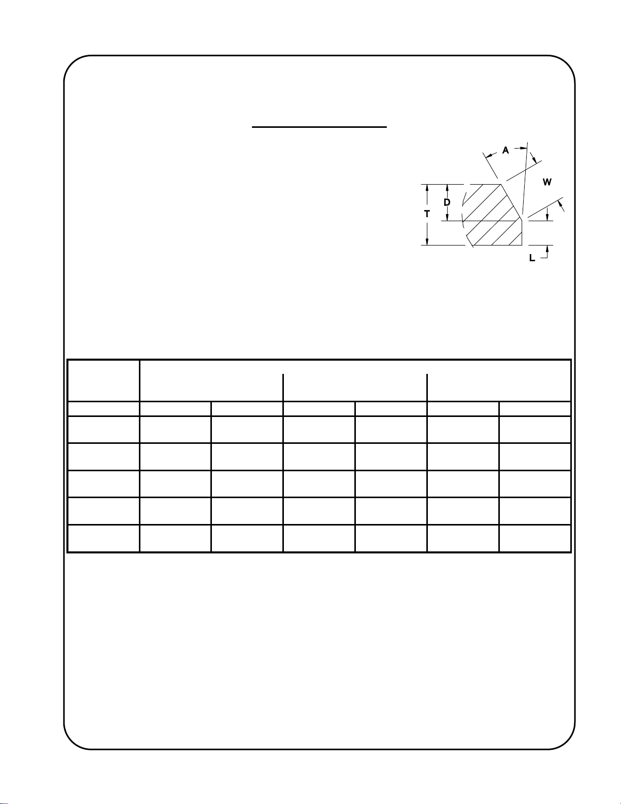
altering the depth and angle of bevel.
A push button, mechanical starter complete with short circuit, motor overload and also under-
voltage protection, is used to start and stop a 2 H.p., 3 phase motor, which in turn uses a heavy
duty industrial type gearbox assembly to drive a serrated cutter. This cutter provides the "Rotary
Shearing" as well the tractive effort to propel either the plate through the machine, or the machine
along the plate, depending on the application.
The KBM®-18 is capable of supporting its own weight while bevelling horizontal plate. The machine
is typically equipped with the optional spring loaded caster assembly that allows the machine to roll
along the floor, or runway, during the bevelling operation. The KBM®-18 machine can be used
without the optional undercarriage assembly to either; be used as a two-man unit in such cases
where it is impractical to use the caster assembly; or it could be bench mounted for applications
where the plate sections are small enough to manually feed through the cutter. The adjustable
bevelling head enables the bevelling of angles 22.5° through 55°.
The KBM®-18 is available for use with the following power supplies; 230, 460 and 575 V at 60 Hz.
and also 380 and 400/415 V at 50 Hz. The supply to be used must be specified at the time of
order. Gullco can also provide machines for use with supplies that are not listed above, please
consult Gullco for more details.
The KBM®-18 machine comes complete with a tool box which includes the bevel angle pins 22.5°,
30°, 37.5°, 45°, and 55°, cutter spacers, and all of the necessary wrenches and hexagonal keys that
are required to make adjustments to the machine.
Note: The machine is shipped from the factory with the 30° bevel angle pin in place.
INTENDED / FORESEEN USAGE
The Gullco KBM®-18 Portable Plate Edge Bevelling machine is used throughout the world to
automate and improve the quality and efficiency of the weld preparation required for manual,
semiautomatic and fully automatic welding operations.
It provides industry with a highly efficient, practical and truly portable method of producing straight
machined bevels on a wide variety of plate materials, including mild steel, stainless steel and
aluminum..... effectively meeting V, X or K weld joint preparation requirements.
Loss of production through operators suffering from skeletal, muscular and hearing loss injuries
normally associated with pneumatic and hand held milling type bevelling equipment is greatly
reduced and detrimental factors such as operator fatigue, or inconsistent workmanship are
eliminated. Required quality levels are consistently attained and productivity and profitability
increased.
‡Top speed can vary depending on variations of bevel depth, voltage and frequency.

7
LIFTING (HOISTING)
When it is necessary to lift (hoist) the Gullco KBM®-18 Portable Plate Edge Bevelling machine, use
the Lifting Plate as shown below (or by using two (2) equal length slings, safely fed through the
machine). All lifting (hoisting) equipment must be suitably rated and clearly identified to be of a
greater capacity than the weight of the machine (as detailed on page 3). Never raise the machine
any higher than necessary and never transport it over the top of people!
WARNING!
Do not lift the machine by the
positioning handle bars, or by
the wheel adjusting handles,
or any other such
component(s) that could result
in machine damage and/or
bodily injury due to
mechanical failure during the
lifting (hoisting) process.
IMPORTANT!
To prevent air from entering the hydraulic
system it is important that the scissor mechanism is not allowed
to open during lifting of the KBM-18 equipped with the hydraulic
undercarriage. Holes are provided to accept a ¾” or 19 mm dia
steel rod (not provided) that will prevent the mechanism from
opening. Otherwise use suitable strapping on the scissor frame.
It is equally important that the rod or strapping be removed
before attempting to use the hydraulic pump to raise the machine
when in use, otherwise the machine can be damaged.

8
INSTALLATION
ELECTRICAL CONNECTION
WARNING! Ensure proper AC earth grounding of the KBM®-18 before applying power. Failure to
do so may invalidate the Gullco Warranty.
WARNING! Before connecting the KBM®-18 to a power source (receptacle, outlet, etc.,) be sure
that the voltage supplied is the same as that specified on the product label. If in
doubt, DO NOT SUPPLY POWER TO THE MACHINE. Copies of the possible
product labels are listed below:
The F.L.A. ratings referenced in the above labels represent the maximum values to which the
adjustable overload setting of the starter switch must be set to and are based on the Full Load Amp
rating of the motor for the voltage being used.
This equipment must be installed in accordance with CEC, NEC or other applicable electrical code.

9
CUTTER
ROTATION PLATE TRAVEL
MACHINE TRAVEL
As the colours of the wires in the mains lead of this equipment may not correspond with the
coloured markings identifying the terminals in your plug/receptacle, proceed as follows:
The Green wire must be connected to the terminal in the plug which is
allocated for “Earth” / “Ground”.
The Black, Red and White wires must be connected to individual terminals in
the plug which are allocated for; “Live 1” (“L1”); “Live 2” (“L2”); and “Live 3”
(“L3”). Before feeding any material into the beveller, check the cutter rotation
as described below, and swap two of these wire terminations at the plug if the
rotation is incorrect.
Note: The mechanical starter is equipped with a low voltage protection device which de-latches
(resets) the Start button whenever the voltage to the machine falls below an acceptable
level. This protects against the machine from accidentally starting up when power is re-
applied.
Note: The Emergency stop push button latches when activated and requires a counter-clockwise
twist to release.
WARNING! As shown in the accompanying drawing, the cutter rotation MUST be clockwise (as
viewed from the front). IT IS IMPORTANT THAT THIS ROTATION DIRECTION BE
CORRECT OTHERWISE DAMAGE TO THE MACHINE MAY OCCUR AND
WARRANTY WILL BE VOID. Be certain to check the cutter rotation before
operating the machine. The plate should be fed in the direction shown if the machine
is static and the material is being manually fed, alternatively, the bevelling machine
should travel in the direction shown if the plate is static and the machine is running
along the plate. If the cutter rotation is incorrect, it means that the 3 phase AC
connection is incorrect and two out of the three Live wires must be swapped. The
correct cutter rotation direction is shown on the clamp roller block.

10
1
3
4
2
MECHANICAL INSTALLATION
WARNING! Check to ensure that no parts have become loose during transportation.
Depending upon the shipping location, the final destination and the method of shipment, various
degrees of re-assembly may be required before initial operation. All of the necessary hardware will
be provided with the machine. Refer to the parts list drawings later in this manual for more
assembly details.
1. The Starter Switch Assembly may need to be re-orientated or re-attached;
2. The handle bars may need re-attaching;
3. The Clamp Roller Assembly may need re-attaching;
4. The Chip Pan may need re-inserting into the optional undercarriage assembly.
5. The anti-rust grease will need to be wiped off prior to use.

11
CUTTER INSTALLATION
The cutter on the KBM-18 is not supplied or installed on the machine unless specified. To install,
first loosen and remove the cutter nut and washer with a 27mm wrench (not supplied). Then
remove and discard the card board and foam spacer that are used to retain the cutter shaft collar
during shipping. Install the cutter onto the shaft, do not apply excess force if the cutter does not
slide on to the shaft easily, there may be burrs or damage on the cutter if it’s been excessively
used.
Reinstall the cutter nut & washer, complete the assembly by firmly tightening the cutter nut.
Cutter nut (27mm) and
washer.
Cardboard and foam spacer,
remove and discard.

12
4
5
6
1
2
3
OPERATION
BEVEL SETTINGS
1. Positively isolate/disconnect the
AC power supply.
2. Clean the area around the Main
Roller and Slide Base Assembly,
then loosen the Slide Base
Clamping Bolt.
3. Lower the Slide Base Assembly
by turning the Slide Base
Adjusting Bolt counter-clockwise.
4. Loosen the nut of the Angle
Alignment Bolt.
5. Loosen the Wing Screw.
6. Tilt the Pivot Arm Assembly
upward.
7. Unscrew and remove the Angle Pin.
8. Screw in the correct Angle Pin to match the desired bevel angle to be produced.
7
8

13
9. Lower the Pivot Arm Assembly
downward while guiding the end of the
Angle Pin into its mating hole in the
Angle Support Bar.
10. Re-tighten the Wing Screw.
11. Using the screws on each side of the
Cutter Shaft Housing, adjust the Angle
Alignment Bolt, up or down, so that the
notched mark on the end of the Angle
Alignment Bolt lines-up with the
appropriate mark engraved on the side
of the Cutter Shaft Housing. The
Alignment Bolt must be adjusted equally
from both sides of the Cutter Shaft Housing to prevent the bolt from twisting. Note: the
alignment is the same for the 37.5º & 45º bevel angles.
10
11
11
9

14
12
13
1
4
1
4
13
12. Re-tighten the nut of the Angle Alignment Bolt.
13. Warning! Ensure that the weight of the
machine is securely supported to prevent
unwanted tipping and that no body parts, or
other items, are located near pinch points prior
to performing this next procedure! In order to
tilt the main body of the machine to the desired
bevel angle, two (2) clamping bolts must be
loosened, allowing the machine to pivot around an
axis at the front of the Tilting Base Frame. The
weight of the main body of the machine will
result in undesirable motion (forward or backwards, depending on the tilt angle) if it is
not properly supported first. Slightly loosen the two (2) bolts, one (1) on each side of the
Tilting Frame Base, so that there is still enough clamping tension to prevent undesirable
tilting motion of the main body of the machine, but sufficient enough to allow the tilting angle
to be manually positioned.
14. Tilt the main body of the machine so that the centre of the rear clamping bolts line-up with
the appropriate marks engraved on each side of the Tilting Base Frame.

15
15 15
1
7
16
15. Re-tighten the two (2) bolts, one (1) on each side of the Tilting Frame Base.
16. Using the Slide Base Adjusting Bolt, adjust the Slide Base Assembly, up or down, to the
desired depth of bevel cut, using the appropriate Angle Reference Scale attached to the
Pivot Arm Block and the fixed Root Face (land) Scale attached to the Slide Base Assembly
as a reference. Note: several set-up and operational elements can affect the accuracy
of the Root Face / Angle Reference Scales. Therefore these scales should only be
used as approximate reference guides and a test run is recommended to check the
actual root face setting. The Angle Reference Scale is slotted to allow the operator to
recalibrate based on an actual bevel. The Root Face Scale is reversible, with inch markings
on one side and millimetres on the other side.
17. IMPORTANT: Ensure that no
dirt or other contaminant has
been trapped behind the Main
Roller, or behind the Slide
Base, and ensure that the
slide base is seated properly,
and then FIRMLY re-tighten the
Slide Base Clamping Bolt.

16
18. Using the adjustable caster handles on each corner of the optional Base Frame Assembly,
adjust the working height of the machine to suit the height of the work table (the top of the
Main Roller, after adjusting to desired bevel depth, is to be the same height as the underside
of the plate to be bevelled). Take care to adjust all four casters so that the machine is level.
Using the hydraulic pump on the optional hydraulic lift undercarriage, adjust the working
height of the machine to suit the height of the work table (the top of the Main Roller, after
adjusting to desired bevel depth, is to be the same height as the underside of the plate to be
bevelled). To lower the working height of the machine, slowly turn the release valve (located
on the pump body) counter clockwise. Turn the valve clockwise once the desired height is
reached
18
Release Valve
Pump Handle
Flow Control Valve
DO NOT ADJUST
Table of contents
Other GULLCO Industrial Equipment manuals