GUS GGW/AGW User manual

Gewässer
Umwelt
Schutz
GmbH
GGW/AGW Glycol protector
Assembly instructions
T
h
e
q
u
a
l
i
fi
c
a
t
i
o
n
o
f
t
h
e
s
y
s
t
e
m
h
a
s
b
e
e
n
p
r
o
v
e
n
b
y
T
Ü
V
R
h
e
i
n
l
a
n
d
.

2oelprotektor.de 3GGW/AGW Glycol protector – Assembly instructions
Product overview
Special sizes:
• GGW/AGW Glycol protector, according to your requirements
Accessory options:
• Leaf protection grating
• Heating kit with heating mats and heating thermostat 3.0
(Heating requirements) for operation of heat pump
• Sensor for second circuit
• Platform to be set up in GGW/AGW Glycol protector
• Fault indicating module (via SMS, Fax oder E-Mail)
Material: GGW Glycol protector stainless 1.4301 in 1,5 mm or
AGW Glycol protector aluminum AlMg3
Process: welding according DIN EN ISO 9606-1
Always study this assembly instruction manual
before installation and initial operation. This
assembly instruction manual is part of the
protector and should be stored close to the
device.
Inhalt
3 Product overview
4 Notes on safe
6 Contents of delivery – GGW/AGW Glycol protec
7 Assembly instructions for – GGW/AGW Gylcol protec
14 Circuit diagram of GGW/AGW Glycol protector switch box/control module
15 Connection plan
16 Service & maintenance, warning notices and leakages
Foreword

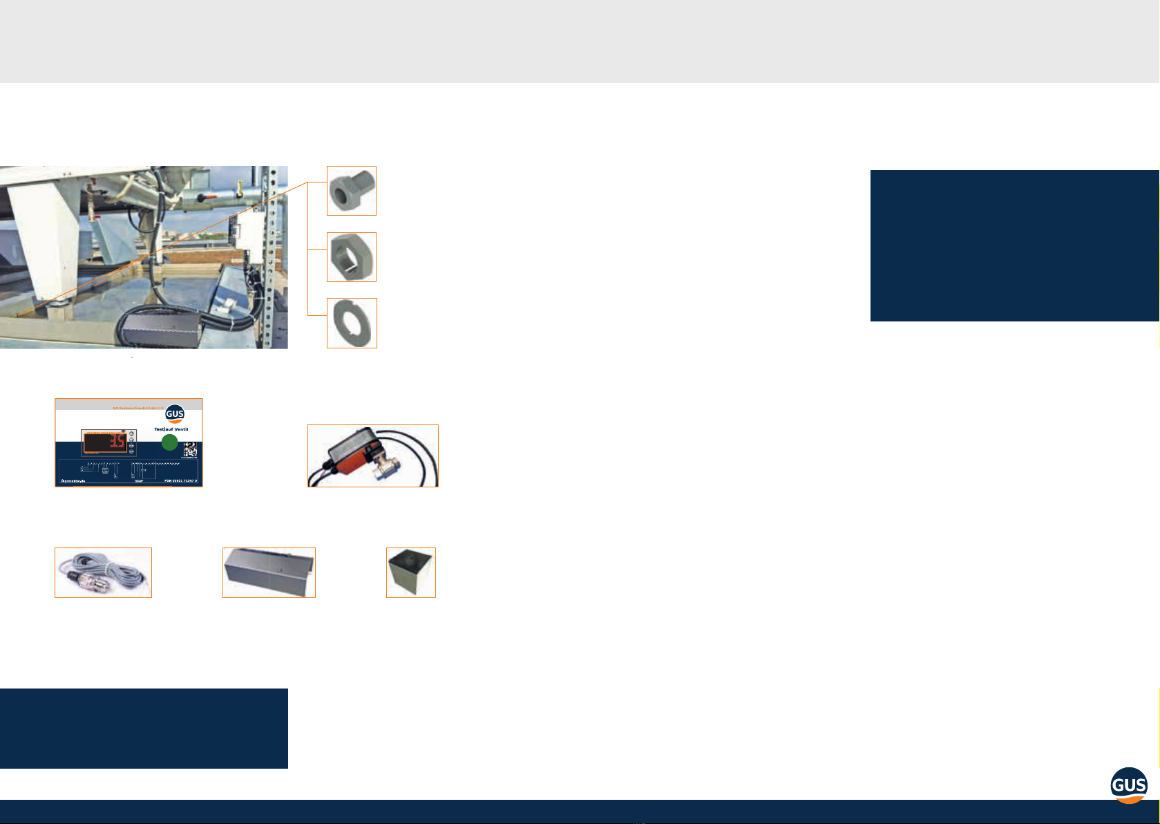
4oelprotektor.de 5GGW/AGW Glycol protector – Assembly instructions
Disposal and packaging
All products are carefully packaged to with-
stand transport damage. Please recycle all
packaging material according to your countries
waste management guidelines.
Warranty
Warranty conditions are outlined in our „All-
gemeine Geschäfts- und Lieferbedingungen“
(General terms and conditions). Please cont-
act your local Distributor.
Description
The handling of material endangering wa-ter
resources is regulated in the Federal water
act and the German „Anlagenverordnung“
(AwSV). Our GGW Glycol protector is manu-
factured from high grade stainless steel or
AGW Glycol protector out of aluminum fullll
these compliance with those regulations.
In the event of leakage, escaping oil and glycol
(water hazard class one till three, according
to legal requirements) will be prevented from
escaping to the surrounding environment.
Please note:
• Keep this manual in close proximity to the unit.
• Setup and assembly of GGW/AGW Gylcol protector and compoments to be carried out
by qualied professionals only.
• Setup, connection and operation of GGW Gylcol protector and components to be
operated for its intended purpose according to this instruction as well as in accordance
with local rules and regulations.
• The condensation pan must be earthed.
• Alterations and modications to our product and its components are prohibited and
can lead to failure or malfunction.
• Do not operate GGW/AGW Gycol protector and components in areas with a high risk
of damage. Specied minimum clearances are to be observed.
• Safe operation of Protector and components can only be guaranteed for properly
assembled devices and use as intended by the manufacturer.
Safety systems may not be modied or bypassed.
• Do not operate damaged or faulty GGW/AGW Glycol protectors or components.
• Protectors and components require a minimum clearance to ammable, explosives,
combustibles, aggressive substances or environments. Assembly, repair and service only
to be carried out by authorised qualied professionals. Visual inspection and
cleaning may be carried out by operator.
• Appropriate measures to be taken to avert danger to individuals while assembling,
repairing, servicing or cleaning GGW/AGW Gycol protector.
Notes on safety
Always read the manual before initial opera-
tion. It contains vital and important tips and
references to avert danger to people as well
as equipment. Disregarding the operating ma-
nual can lead to endangerment of individuals,
the environment and damage to the unit. We
reject liability for neglectful operation.
Recycling
GGW/AGW Glycol protector with its integrated
oil separator is designed to withstand the
most extreme precipitation events ever recor-
ded in Germany. It will safely drain the liquids
away withouth spilling, thereby preventing
overow.

6oelprotektor.de 7GGW/AGW Glycol protector – Assembly instructions
Contents of delivery GGW/AGW Glycol protector Installation instruction GGW / AGW Glycol protector
When choosing the appropriate size make
sure all water hazarduous components can be
tted within the GGW/AGW Glycol protector.
Make sure the oil separator is not covered by
the unit and rain water can reach the pan.
Ensure a supporting structure able to support
the weight of the 1.5 mm stainless steel de-
vice without deformation.
Note:
Installation to be carried out by 2 person-
nel. More complicated structures will be
accompanied by a drawing. Make sure to
align pan properly, resting rmly on the
supporting structure.
connecting screws ½“,
3 per connection level
screw nut ½“,
3 per connection level
washer,
6 per connection level
1 pressure sensor ½“
(incl. 5 m cable)
1 switch box (control module)
IP65 protected and UV-resistant
1 safety valve with actuator
1 protective cover platforms,
either standard
or made to
your requirements
Note:
Check delivery for completeness
Alignment
The supporting structure is to be aligned ho-
rizontally using a spirit level to ensure proper
operation. Clean all surfaces before levelling.
Assembly parts for pan according to drawing
DRUCK

8oelprotektor.de 9GGW/AGW Glycol protector – Assembly instructions
Align rst part of pan vertically with outer
edge of supporting structure. Assembling the
pans is illustrated in drawings. Note position
of separators.
Connecting
Connect all parts with connecting screws. Use
loctite to secure threads. Place washer onto
thread and put screw through drilled hole.
Put second washer onto protruding thread.
Add more loctite and tighten screw nut by
hand. Use same routine for remaining screws.
Use appropriate tool to tighten screws, achie-
ving a watertight connection.
Place second part of pan into rst part as
per drawing. Follow the same procedure with
remaining parts. Make sure not to bend ma-
terial.
upended side
Assembly
Note:
Make sure pan is resting rmly on suppor-
ting structure and oberserve drying time
of loctite.

10 oelprotektor.de 11GGW/AGW Glycol protector – Assembly instructions
Choose one of three actuator positions on valve
body. Positioning of actuator determines posi-
tion of pan. When installing the valve observe
direction of ow indicated by arrow on valve.
Screw valve onto welded cone at drainage
point of GGW Glycol protector.
To allow condensation to be drained, a second
¾“ connection can be used. Make sure to pro-
vide a bleeding function, thereby eliminating
the risk of the separator running dry. Elec-
trical connections to be made according to
connection plan.
A cover is provided for every valve. Make sure
to install it when running the device in an out-
side area.
Platform
Apply an oil and water repellant sealing com-
pound to the underside of the platform (e. g.
Silicone). Position platform in protector.
silicone seam
Note:
If the pan is accidently damaged when
drilling, perform a pressure test for 24
hours to ensure leak tightness
Make sure to connect the device with the
platform and the separator to the supporting
structure. Be aware that perforation can lead
to leakage problems. We recommend a con-
struction surrounding the pan. If you have
to drill make sure to seal the hole properly.
We can provide information on di erent fas-
tening methods.
Fastening
Pressure sensor test port
The cold water circuit needs to have a ½“
internal threaded connection for the pressure
sensor. Make sure the test port can be isola-
ted from the circuit so you can replace the
pressure sensor without having to drain the
system.
We can supply you with a copper adapter
which includes a Schrader-Valve to be solde-
red into place. Please take note to remove the
Schrader-Valve during soldering.
Screw pressure sensor onto existing or newly
attached test port. Pressure sensor to be
tightened with max 30 NM to avoid damage.
When connecting the pressure sensor, refer to
connection diagramm (Page 14). A 5 m cable
is included with the pressure sensor for ½“
external thread-connection. Position the two
wires according to connection plan.
Safety valve with actuator
incl. 5 m cable
Observe drawing. Seal exterior of platform with
oil and water repellent material (e. g. Silicone)

12 oelprotektor.de 13GGW/AGW Glycol protector – Assembly instructions
The control module is monitoring the Glycol
pressure. It is IP65 protected and UV
resistant and includes a microprocessor,
relays, terminal blocks and complete inter-
nal wiring. It is tted with a push-button to
check operation. Pressure uctuations are
monitored and assessed. The valve will be
closed in case of leakage. The red signal
indicates the current pressure.
Correct operation is indicated by a green
„Druck“ (pressure) sign.
The LED display ticker „Druckabfall“
(pressure drop) indicates a leak. The green
push-button will close the valves for an ope-
rational check.
Switch box/controle module
switch box (controle module)
IP65 protected and UV resistant
pressure sensor
protective cover
(per safety valve)
platform
Note:
Warning!
An alert will be send to GLT when valves
are completely closed. The control modu-
le requires a 230 V supply. Follow connec-
tion plan.
Operation
Di erent levels of con guration are accessed
via key combinations. The User-level is suffi -
cient for device operation.
All other con guration levels are secured with
a PIN. Activate User-level by pushing PGM-Key
twice. Arrow-key will move cursor to parame-
ter to be adjusted.
Parameters available:
DRUCK (Pressure):
Operating pressure
Choose the parameter using the arrow keys.
Press PGM key to activate and change set-
tings with the arrow keys. This setting will be
saved automatically after ten seconds. Pres-
sing the PGM key will fast track the procedure.
DRUCK (Pressure)
is the consigned operating pressure.
DRUCK
All pressure alarms have to be reset. A reset is
only possible once correct operating pressure
has been restored.
Press „F“/„Exit“-key for two seconds „Ventil-
signal“ (Valve signal) appears in Display. A
defect valve will also trigger „Ventilsignal“ in
Display.
The system distinguishes between Gylcol pro-
tector errors and errors triggered by loss of
pressure.

14 oelprotektor.de 15GGW/AGW Glycol protector – Assembly instructions
optionally expandable
to number X
potential free
Alarm contact
optionally
expandable to
number X
contact ½
optionally
expandable to
number X
contact ¾
Terminal series 1
Terminal series 3
Terminal series 2
Terminal series 1
<85 % open
<10 % geönet
0-10 bar
3mA
1
2
3
4
5
6
7
8
9
10
11
12
13
14
15
17
16
18
19
20
21
22
23
24
25
26
27
28
29
30
S1E
S3 S1S3 S1
S5 S4
S11
L1PE N
Recommendations for cable routing:
Connection plan
Circuit diagram of
GGW/AGW Glycol
protector-switch
box/control module Supply cable for switch box NYM 3 x 1,5²
Control cable for pressure sensor switch box Oelex 2 x 0,75² (abgeschirmt)
Supply cable for valve switch box Oelex 2 x 1,5²
Control cable for valve switch box Oelex 4 x 1,5²
Terminal block
switch box
Terminal block
pressure sensor
Terminal 7 Terminal 1
(white)
Terminal 8 Terminal 2
(brown)
Terminal block
switch box
Terminal block
valves
Terminal 17 Terminal 1 (brown)
Terminal 23 Terminal 2 (blue)
Terminal 11
Terminal S4 (4)
Terminal 12
Terminal S5 (5)
Terminal 13
Terminal S1 (1)
Terminal 14
Terminal S3 (3)
Ph Terminal L 1
N blue terminal strip
PE green terminal strip
Connection Voltage supply switch box
(1.5 mm²)
Connect pressure sensor (0.8 mm²)
Connecting valves (1.5 mm²)
Note:
Make sure the display is clearly visible
when mounting the control module.
For any questions regarding assem-
bly, implementation or service please
contact our service telephone at:
+49 5921 71347-0.
UV-resistant if exposed to sun light

16 oelprotektor.de 17GGW/AGW Glycol protector – Assembly instructions
Service & maintenance, warning notes und leakage
Leakage
Check the GGW/AGW Glycol protector if a lea-
kage is detected. Collected water of the GGW/
AGW Glycol protector must be dis-posed pro-
perly. For this purpose a ¾“ connection can be
screwed on the drain and the process can be
opened by acknowledging the error message.
Alternative: Open the valve manually with the
supplied manual drive.
Service & maintenance
When servicing the unit in regular intervalls,
always check and clean the GGW/AGW Glycol
protector. Leaves and other contaminants can
compromise the oil separator´s performance.
The oil separator can be rinsed via the water
drainage. Within the scope of the maintenance,
please press the green button for the control
of the valve for 10 seconds in order to remove
deposits in the valve and to check the functio-
ning of the fault signaling device.
Note:
For any questions regarding assembly, implementation or service please contact our
service telephone at: +49 5921 71347-0.
Warning notes
Please note that dierent detergents dissolve
oil in water. The GGW/AGW glycol protector
must be rinsed with water until no detergent
is left in the GGW/AGW glycol protector if such
cleaning has been used.
Avoid bi-metal corrosion by keeping other
metal parts separate from GGW/AGW Glycol
protector.
If there are any water-polluting substances
in the GGW/AGW Glycol protector you have
to shut down the system immediately and
inform your refrigeration and climate expert.
The water-polluting substances are to be
disposed of professionally.

18 oelprotektor.de 19GGW/AGW Glycol protector – Assembly instructions
Notes

GUS
Gewässer-Umwelt-Schutz-GmbH
Bentheimer Straße 300
48531 Nordhorn
T: +49 5921 71347-0
info@oelprotektor.de
oelprotektor.de
We reserve the right to amend this document.
Any liabiliy for errors and misprints of this document is excluded.
March 2021
Table of contents
Other GUS Industrial Equipment manuals