Guth Laboratories 12V500 DUPLEX User manual

GUTH LABORATORIES, INC.
Wet Simulator
Model 12V500
OPERATOR’S MANUAL
www.guthlabs.com
“DUPLEX”
U.S. PATENT NO. 7,895,878; 8,667,829
CANADIAN PATENT NO. 2684266
GUTH LABORATORIES, INC.

©2015 Guth Laboratories, Inc./all rights reserved

INTRODUCTION
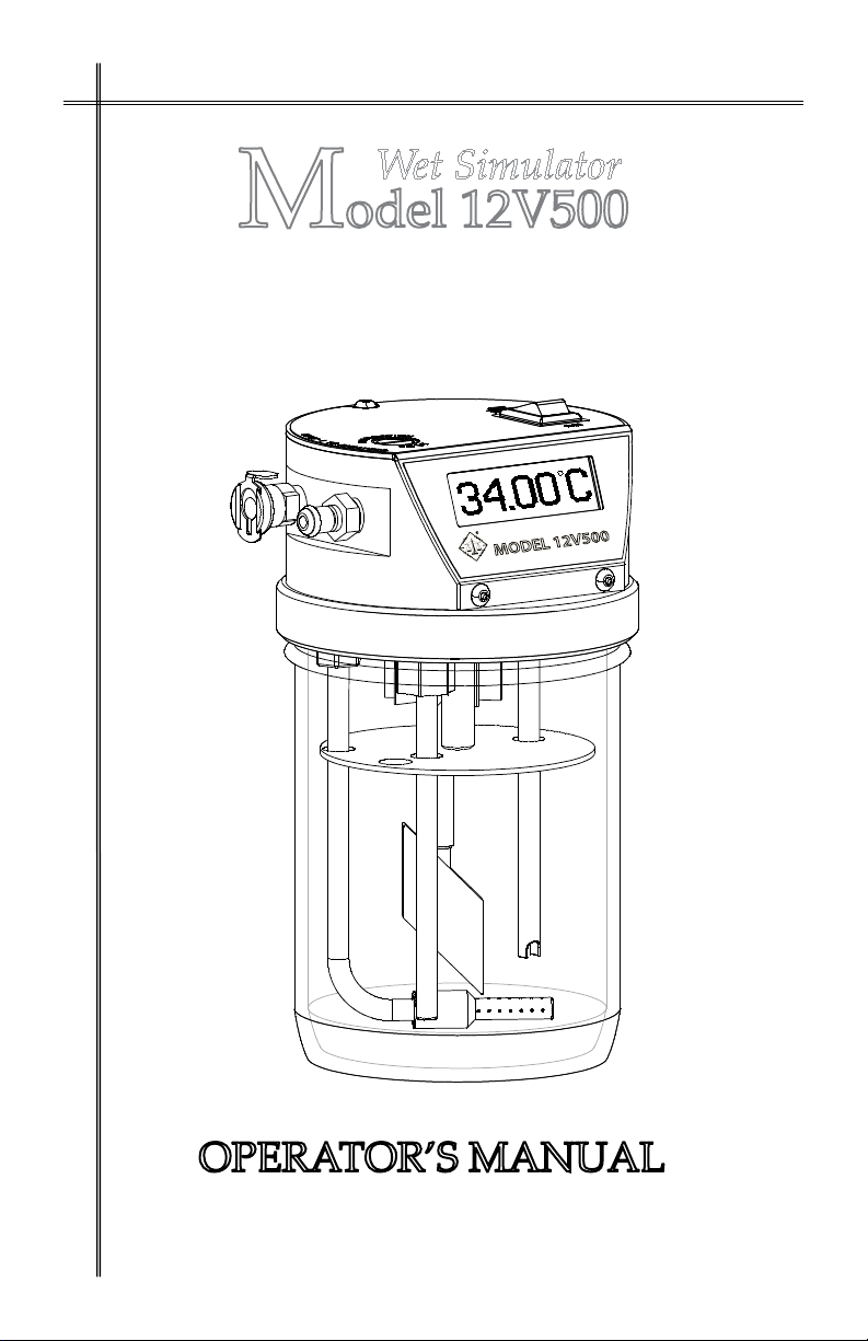
The Guth Model 12V500 Alcohol Breath Simulator is a State-of-the-Art, electroni-
cally temperature controlled, water-alcohol instrument for the purpose of providing
a precise calibration standard for testing or calibration of alcohol breath analyzers.
The Model 12V500 is the rst simulator of its kind to incorporate dual temperature
probes to independently control and monitor the temperature of the solution. The
temperature of the water-alcohol solution placed in the simulator is maintained at
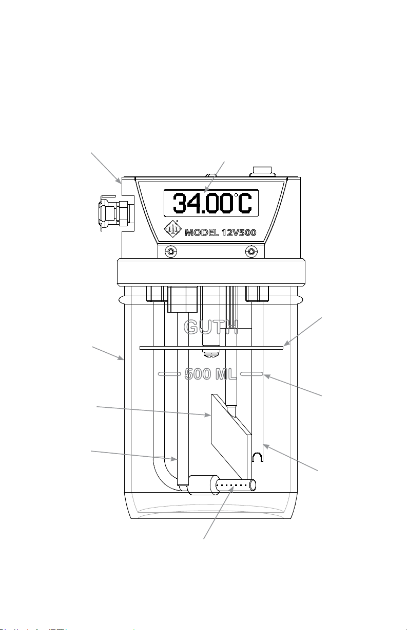
34° C ± .05° C or better. The inlet and outlet port pathways have been designed to
be an integral part of the one piece heated aluminium top housing thus allowing
uniform heating and reduction of condensation. The new LCD graphics display has
a temperature resolution of .01° C and will display simulator status to the user in
the form of messages and status codes. As with all Guth products the 12V500 has
been engineered using the highest quality components to give reliable, accurate and
trouble free operation.
CERTIFIED SIMULATOR SOLUTION STANDARD
PLEASE NOTE: It is imperative your Simulator Solution be of the highest quality in
ordertoacquirethescienticandlegalstandardsofacceptance.
To establish a precise and accurate calibration standard when using a Guth Simulator,
GUTH LABORATORIES, INC. recommends using Guth Certied Simulator Solu-
tion. Guth Laboratories, Inc., a pioneer and leader in the science of alcohol breath
testing, has provided Certied Simulator Solution to state, municipal, and local law
enforcement agencies for many years.
************
All Guth Certied Simulator Solutions are traceable to NIST (National Institute of
Standards and Technology).
************
Guth Certied Simulator Solutions are prepared in standard concentrations of .02%,
.04%, .05%, .08%, .10%, .15%, .20%, and .30%. Other special concentrations are
available upon request. Please contact Guth Laboratories, Inc. for availability and
pricing:
Toll Free: (800) 233-2338 Fax: (717) 564-2555
or visit our web site at: www.guthlabs.com
STORAGE: Store Simulator Solution in a cool location. Do not place
solution in a freezer.
- DO NOT REFRIGERATE SIMULATOR
1

COMPONENTS & FUNCTIONS
1. TOP HOUSING - The top housing incorporates all the important features
of the simulator. The housing is heated and controlled by use of a head space
heater (U.S. Patent # 8,667,829).
2. LCD DISPLAY - The display indicates the temperature of the solution with
a resolution of .01° C. It also serves to give feedback to the user during use by
displaying status messages. The display is back lighted to allow easy viewing in
all lighting conditions.
3. TEMPERATURE PROBE - The temperature probe consists of two separate
ultra-stable precision thermistor beads. One thermistor bead is used to control
the temperature of the solution at 34° C ± .05° C and the other independently
monitors the temperature of the solution. In the event of either probe failing a
status message is generated on the display.
4. HEATING ELEMENT - The heater element is used to heat the solution to
34° C. It is electronically protected from overheating if the simulator would be
turned on without solution in the container. In the event of a heater failure a
status message will be generated on the display.
5. BAFFLE PLATE - The bafe plate prevents excess solution from entering
the head space or outlet port during a test.
6. AGITATOR - The agitator designed by Guth Laboratories, Inc. stirs the solu-
tion to help maintain a uniform temperature. If the motor fails a status message
will be displayed on the screen.
7. DISPERSION TUBE - A unique dispersion tube disperses the delivery air
uniformly throughout the solution. Tube may be disassembled for cleaning.
8. GLASS CONTAINER - The glass container holds the solution and creates
an airtight seal with the top housing. There is a mark on the container indicating
the solution level at 500 ml ± 5% (#9, Page 3).
10. U.H.C. (Uniform Headspace Conditioner) - To ensure all tests performed
by the Guth Model 12V500 are precise and accurate, an eight (8) blade radial
fan is designed and included in the headspace area. The headspace area is heat-
ed by an imbedded controlled heater. The radial fan provides uniform headspace
heating and the efuent at a constant concentration. Patent Pending.
2

MODEL 12V500
(Front View)
3
GUTH LABORATORIES, INC.
7. DISPERSION TUBE
4. HEATING
ELEMENT
9. SOLUTION
LEVEL
MARK
500 ml ± 5%
8. LABORATORY
GLASS
CONTAINER
5. BAFFLE
PLATE
6. GUTH
AGITATOR
3. DUAL ULTRA-STABLE
PRECISION
THERMISTOR BEADS
1. TOP HOUSING
NONMAGNETIC/EPOXY POWDER COAT
INTERNAL MANIFOLD DESIGN
2. BACKLIT
LCD GRAPHICS
DISPLAY

MODEL 12V500
(Rear View)
11. INPUT POWER JACK - The power jack serves as the input connector for
the external power supply. The 12V500 can be run from the included desktop
switching power supply or any 12VDC source capable of supplying 8 amps.
12. RS-232 COMMUNICATION PORT -The RS-232 port allows the simula-
tor to be interfaced with breath analyzers that support serial communications.
4
11. INPUT
POWER
JACK
(12VDC @ 8 amps)
12. RS-232
COMMUNICATIONS
PORT
10. U.H.C.
(Uniform Headspace
Conditioner)

MODEL 12V500
(Top View)
13. POWER SWITCH - The power switch is used to turn the simulator ON/
OFF. It also functions as a RESET switch.
14. CALIBRATION PORT - The calibration port allows the temperature of the
solution to be measured with an external digital or mercury thermometer.
15. FEMALE INPUT CONNECTOR - The standard input connector is a
1/8” ow female SureLoc that allows for easy and secure hook up to various air
delivery methods. (Customized tting options available)
16. MALE OUTPUT CONNECTOR - The standard output connector is a
1/8” ow male SureLoc that allows for easy and secure hook up for delivering
the calibration sample to various breath analyzers. (Customized tting options
available) 5
15. 1/8”FLOW
FEMALE
INPUT
CONNECTOR
16. 1/8” FLOW
MALE OUTPUT
CONNECTOR -
TO
BREATH ANALYZER
14. CALIBRATION
PORT
13. POWER
SWITCH

MODEL 12V500
POWER SUPPLY
17. POWER SUPPLY - The included UL listed desktop switching power
supply is capable of accepting an input from 100 - 240 VAC and providing an
output of 12 VDC at 8.33 amps.
18. POWER OUTPUT CONNECTOR - The output connector supplies power
to the 12V500. This connector plugs into the power jack on the rear of the
simulator.
19. IEC60320-C14 - Accepts the female connector (IEC 60320-C13) for con-
necting the AC power cord to the power supply.
20. AC Power Cord - Used to connect the power supply to the AC power
source.
20a. NEMA5-15P - Plugs into wall socket or receptacle.
20b. IEC60320-C13 - Plugs into the male inlet (IEC 60320-C14) for
connecting the AC power cord to the power supply.
*OnlyusedinNorthAmerica.
17. External Switching
Power Supply
20a. AC PLUG,
NEMA 5-15P*
19. IEC60320-C14,
Male
Inlet
20b. IEC 60320-C13,
Female
Connector
18. Power
Output Connector
(12VDC @ 8.33 A)
20. AC Power
Cord
6

OPERATING INSTRUCTIONS
1. Unscrew the glass container from the simulator top housing. Pour 500 ml
of Certied Simulator Solution into the container. The Guth laboratory glass
container has a 500 ml ± 5% ll mark.
2.Reassemble the simulator with the glass container. Be sure the container is
properly seated to the top housing. DO NOT OVERTIGHTEN. To check that
the system is airtight cover the outlet port while blowing into the input port. If
back pressure is evident and very few air bubbles are observed emanating from
the dispersion tube the system is airtight.
3. Insert output connector from external power supply to input power jack of
simulator. Insert AC power cord into power supply. Plug power supply into
wall outlet.
4. Turn the power ON. The simulator will beep and the screen shown in gure
1 will be displayed.
5. After approximately 5 seconds the display will change to the screen shown
in gure 2. During this time the simulator will perform an internal diagnostic
check.
6. Figure 3 will be displayed during the warm up cycle. The snow ake icon
indicates that the simulator is still cold and is not ready for use. The temperature
of the solution is displayed in the upper right hand corner of the screen. The
bottom right hand corner shows the status of the top housing temperature.
V1.01
FIGURE 1
FIGURE 2
FIGURE 3
7

7. The solution temperature will increase until the set point of 34.00° C has been
attained. When the set point for the top housing is reached the status bar will no
longer blink and will be completely lled to the right (Figure 4).
8. After both set points have been reached there will be a period of approxi-
mately 1 minute before the ready screen will be displayed (Figure 5).
FIGURE 4
FIGURE 5
8
9. The simulator will beep indicating that it is ready. It is normal for the simula-
tor to display temperatures in the range of 33.95° C to 34.05° C.
10. Follow the operators manual provided by the manufacturer of the breath
analyzer being used for detailed instructions on how to connect and use the
simulator to perform a calibration or accuracy check. See diagram on next page
for basic hookup and operation.
When manually operating the simulator, take a deep breath and blow
into the mouthpiece rmly and steadily for a 4 to 7 second duration. The blow-
ing technique should imitate a person providing a breath sample into the breath
test analyzer.
Rather than manually blowing into the simulator, the following alterna-
tive means also fulll the requirement of providing air through the tubing at-
tached to the simulator: the breath analyzers internal pump, a simulator bellows
pump, a pump-powered air source, or an atomizer. Several precision models of
pumps are available for purchase through Guth Laboratories, Inc.

0.079%
BLOW
BREATH
ANALYZER
MOUTHPIECE
AIR IN
CALIBRATION
VAPOR OUT
9

CARE & MAINTENANCE
Cleaning the Simulator -
The top housing may be cleaned using a mild detergent and a soft cloth.
To clean the components within the container and destroy any algae mix 1 TA-
BLESPOON (15ml) of CHLOROX per 1 GALLON (3.75L) of WATER. Pour
approximately 500 ml of prepared chlorox solution into container and replace
top assembly. Soak for 3-6 hours, remove container and carefully rinse compo-
nents with cold water (DO NOT rinse with HOT water). Hot water could shock
or break the thermistors. Do not allow water to enter top housing while rinsing.
Allow the simulator to AIR dry before returning to service.
Maintaining the Simulator -
Inspect the laboratory glass container, with every solution change, for chips or
cracks that may prevent an airtight seal. Replace if necessary.
Inspect the container gasket looking for uneven wear , cracking, or tears. Re-
place if necessary. The gasket should be lubricated periodically using silicone
grease. Packets of silicone grease are available for purchase from Guth Labora-
tories, Inc. (P/N: GU-1170-SG).
Inspect the ‘O-ring on the male sureloc connector for wear. Replace if necces-
sary.
Inspect the thermistor beads for buildup of algae. If algae is present please fol-
low the directions detailed above for cleaning components within the container.
Over time the holes in the dispersion tube may become blocked impeding air
ow into the simulator. To clean the dispersion tube remove it from the stain-
less steel inlet pipe by pulling it free. Once free a wire brush may be used to dis-
lodge any debris within the tube and the holes may be cleaned with a small pick.
Thoroughly rinse the dispersion tube before reassembling.
Guth Laboratories, Inc. recommends that the temperature of the 12V500 be
checked at least once per year.
TEMPERATURE CHECK
10

Trouble Shooting
The Model 12V500 provides internal diagnostics that monitor proper simula-
tor operation. If a monitored system detects a condition that is outside of the
normal operation parameters, the simulator will deactivate the solution and head
space heaters as well as the agitator motor. The simulator will emit an audible
alarm and display the detected condition code number on the LCD followed by a
message and icon detailing the condition. The LCD will alternate displaying the
status code and message until the condition is corrected or the simulator is reset.
The audible alarm will stop after 1 minute.
Resetting The Simulator
Turning the power off and on will reset the simulator.
Status Codes and Messages
The following list of status codes and messages indicate the cause and corrective
action:
11
PROBLEM: No solution in container or simulator power has been turned on
with top housing not attached to the container.
REMEDY: Turn the simulator off. Fill container with 500 ml of certied solu-
tion and reassemble top housing and container.
PROBLEM: The temperature sensor for the heater control circuit is either
open or shorted.
REMEDY: Cannot be remedied in the eld. Requires service.*

12
PROBLEM: The temperature sensor for the thermometer circuit is either open
or shorted.
REMEDY: Cannot be remedied in the eld. Requires service.*
PROBLEM: Temperature of solution is above 34.20° C after initially reaching
34.00° C.
REMEDY: Turn off the simulator and allow the solution to cool. Turn the
simulator on. If the condition continues to occur the simulator needs to be rec-
alibrated or requires service.*
PROBLEM: Excessive amount of time for solution temperature to increase.
The heating element may be open or the solution was too cold.
REMEDY: Reset the simulator. If the simulator does not heat, the heating ele-
ment may be defective. Requires service.*

PROBLEM: Temperature of solution has dropped below 33.80° C after ini-
tially reaching 34.00° C.
REMEDY: Turn off the simulator. Wait a few minutes then turn back on. If
the condition continues to occur the simulator needs to be recalibrated or re-
quires service.*
PROBLEM: The temperature control circuit and the thermometer are reporting
different temperatures.
REMEDY: The simulator needs to be recalibrated.
PROBLEM: The agitator is not spinning.
REMEDY: Turn the simulator off. Remove container from simulator. Check
for and clean any corrosion that has built up around the motor shaft. Manually
spin agitator by hand. If agitator spins freely reassemble simulator. If the condi-
tion continues service is required.*
13

14
PROBLEM: Temperature of top housing has dropped below 34.5° C after
initially reaching set point.
REMEDY: Turn off the simulator. Move simulator into a warmer environ-
ment. Wait a few minutes then turn back on. If the condition continues to occur
the simulator requires service.*
PROBLEM: Temperature of top housing has risen above 36.0° C.
REMEDY: Turn off the simulator. Move simulator into a cooler environment.
Wait a few minutes then turn back on. If the condition continues to occur the
simulator requires service.*
PROBLEM: Excessive amount of time for top housing temperature to in-
crease. The heating element may be open or the top housing was too cold.
REMEDY: Reset the simulator. If the top housing does not heat, the heating
element may be defective. Requires service.*

* REQUIRES SERVICE - Simulator must be repaired by a Guth certied
technician or returned to Guth Laboratories, Inc. Please call our Product Service
Department for assistance or a RMA (Return Material Authorization) number.
Return the simulator to the following address:
GUTH LABORATORIES, INC.
590 North 67th Street
Harrisburg, PA 17111-4511
(717) 564-5470 or (800) 233-2338
NOTE: When returning the simulator, it is imperative the laboratory glass
container is attached. This is necessary to protect critical parts of the
simulator. Please empty the solution from the container and thoroughly dry
all components. Carefully wrap the simulator in bubble wrap, newspaper,
paper towels, etc. Package the simulator well placing packing material
UNDER, AROUND, and ABOVE the simulator. Insure your package for
$650.00 per simulator.
15

UNDERWRITERS LABORATORIES, INC.
UL SYMBOLS AND WARNINGS
!
Power Supply: Input : 100-240 VAC 47-63Hz.
Output: 12VDC @ 8.33 Amps
Max Power Output of 100 Watts
Model 12V500 Power: 12VDC, 82Watts
Mains supply uctuation not to exceed ±10% of the nominal voltage.
Do not position instrument so that it is dicult to disconnect the power
cord.
Disconnect power cord and empty solution before moving instrument.
Disconnect power cord before changing solution.
Disconnect power cord before replacing fuse.
Fuse Replacement: Littelfuse - Type Nano2, 8 Amps @ 125 VAC, Very Fast Acting
Internal Fuse - To be changed by qualied personnel only!
Temperature 1°C to 33°C (34°F to 91°F)
Maximum Relative Humidity 80% for Temperatures up to 31°C
(~88°F), decreasing linearly to 50% Relative Humidity.
Transient Over voltages according to Installation Category II.
When Instrument is operated at an elevated temperature, the outside of the
glass container may become hot.
16

RECORDS (SERIAL NUMBERS, CALIBRATION AND NOTES)
NIST TRACEABLE THERMOMETER – SERIAL NUMBER___________________
CERTIFIED BY________________________________DATE_____________
TEST TEMPERATURE_______ CNIST TRUE TEMPERATURE_______ C
MODEL 12V500 – SERIAL NUMBER_________________________________
CALIBRATION CHECK DATE CHECKED BY
NOTE: Only a Guth Laboratories, Inc. certied technician shall perform Field
calibration.
17

WARRANTY
Simulators manufactured by GUTH LABORATORIES, INC. are guaranteed to
be free from defects in workmanship and material for a period of one year from
the date of purchase. GUTH LABORATORIES, INC. will repair or replace,
at its option, any unit becoming defective within that period, except when such
defects result from obvious abuse or improper use of the instrument.
Simulators serviced and repaired by GUTH LABORATORIES, INC. will carry a
ninety (90) day workmanship guarantee, except when obvious abuse or improper
use is determined. When a defective part is replaced under warranty, the new
part will be guaranteed for the duration of the original warranty, or a period of
ninety days, whichever is greater. When a defective part not under warranty is
replaced, the new part will be guaranteed for ninety days.
This warranty by GUTH LABORATORIES, INC is subject to the following
conditions:
GUTH LABORATORIES, INC.:
A) Reserves the right to determine whether failure
is or is not covered by the warranty.
B) Will not honor any obligations, expressed or
implied, except as so stated above.
C) Is not liable for any inconvenience, loss of use,
or consequential damages resulting from service
requirements.
D) Will not honor service by any unauthorized agen-
cies or modications by user.
If your simulator requires warranty service, please call (800) 233-2338 for a
Return Material Authorization Number (RMA#). It is imperative that the solu-
tion be emptied, and the container must accompany the simulator top assembly
to protect the internal parts against damage. Returning the simulator without the
container will void the warranty. When returning the simulator to the factory,
please pack carefully and insure for $900 per simulator. Shipping charges, du-
ties, and taxes must be prepaid. Return shipping to the customer is paid by Guth
Laboratories, Inc.
WARNING: Your simulator will not be covered by this warranty unless the
Warranty Card is completed and returned to GUTH LABORATORIES, INC.
Within ten (10) days of purchase.
18
Table of contents
Other Guth Laboratories Laboratory Equipment manuals
Popular Laboratory Equipment manuals by other brands

BIOMET
BIOMET Clotalyst manual

Endress+Hauser
Endress+Hauser Liquistation CSF48 operating instructions

Metrohm
Metrohm 916 Ti-Touch Manual - Short Instructions

Velp Scientifica
Velp Scientifica ARE instruction manual

GE
GE Filter Kit HR 10 instructions

Johnson & Johnson
Johnson & Johnson Sterrad 100NX user guide