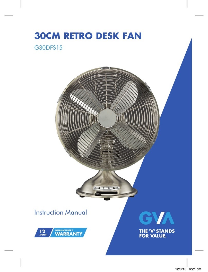
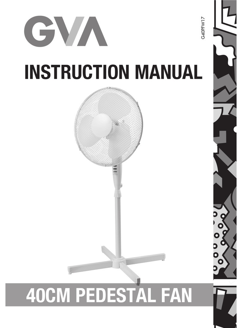
GVA G45PFW16 User manual

8
9
10
11
12
1
2
3
4
5
6
7
13
14
COOL SPEED TIMER SWING ON/STANDBY
Fig.1
ON/STANDBY
COOL
SWING
TIMER
SPEED
CANCEL
TIMER
Fig.2
(Fig.7)
(Fig.6)
(Water Curtain)
(Fig.4)
(Filter)
Press the two clips down
and then pull the filter out.
(Fig.5)
Screws
Back cover
Water drainage outlet
Fig.3
8
9
10
11
12
1
2
3
4
5
6
7
13
14
COOL SPEED TIMER SWING ON/STANDBY
Fig.1
ON/STANDBY
COOL
SWING
TIMER
SPEED
CANCEL
TIMER
Fig.2
(Fig.7)
(Fig.6)
(Water Curtain)
(Fig.4)
(Filter)
Press the two clips down
and then pull the filter out.
(Fig.5)
Screws
Back cover
Water drainage outlet
Fig.3
45CM
PEDESTAL FAN
G45PFW16
Instruction Manual
GVA PRODUCTS DETAILS
File Name: IM_G45PFW16_OLN9258_V0.06_TC050516
Name: 45CM PEDESTAL FAN
Proof Version: Proof 1
Date: 5th May 2016
M.E.W. (Australia) Pty Ltd
15 Vaughan St
Essendon Fields VIC 3041
ACN 152 719 036
1300 725 885
gvaproducts.com.au
While every effort has been made in the preparation of this instruction manual, the publishers cannot be held
responsible for the accuracy of the information contained herein or any consequences arising from it.
5/05/16 2:37 PM

8
9
10
11
12
1
2
3
4
5
6
7
13
14
COOL SPEED TIMER SWING ON/STANDBY
Fig.1
ON/STANDBY
COOL
SWING
TIMER
SPEED
CANCEL
TIMER
Fig.2
(Fig.7)
(Fig.6)
(Water Curtain)
(Fig.4)
(Filter)
Press the two clips down
and then pull the filter out.
(Fig.5)
Screws
Back cover
Water drainage outlet
Fig.3
8
9
10
11
12
1
2
3
4
5
6
7
13
14
COOL SPEED TIMER SWING ON/STANDBY
Fig.1
ON/STANDBY
COOL
SWING
TIMER
SPEED
CANCEL
TIMER
Fig.2
(Fig.7)
(Fig.6)
(Water Curtain)
(Fig.4)
(Filter)
Press the two clips down
and then pull the filter out.
(Fig.5)
Screws
Back cover
Water drainage outlet
Fig.3
Guide to the Appliance 2
Caring for the Environment 3
Safety Information and Warnings 4
Items in the Box 5
Basic Set-up 6
Operation Instructions 7
Care and Maintenance 7
Technical Specifications 8
Contents G u i d e t o t h e A p p l i a n c e
1. Fan Grilles
2. Fan Blade
3. Oscillation Knob
4. Motor Housing
5. Switch Box
Note: Due to production improvements, the appliance may differ slightly from the diagram shown.
Diagrams in this instruction manual are for reference only.
6. Inner Tube
7. Height Adjustment Collar
8. Outer Tube
9. Base
1 2
5/05/16 2:37 PM

8
9
10
11
12
1
2
3
4
5
6
7
13
14
COOL SPEED TIMER SWING ON/STANDBY
Fig.1
ON/STANDBY
COOL
SWING
TIMER
SPEED
CANCEL
TIMER
Fig.2
(Fig.7)
(Fig.6)
(Water Curtain)
(Fig.4)
(Filter)
Press the two clips down
and then pull the filter out.
(Fig.5)
Screws
Back cover
Water drainage outlet
Fig.3
8
9
10
11
12
1
2
3
4
5
6
7
13
14
COOL SPEED TIMER SWING ON/STANDBY
Fig.1
ON/STANDBY
COOL
SWING
TIMER
SPEED
CANCEL
TIMER
Fig.2
(Fig.7)
(Fig.6)
(Water Curtain)
(Fig.4)
(Filter)
Press the two clips down
and then pull the filter out.
(Fig.5)
Screws
Back cover
Water drainage outlet
Fig.3
C a r i n g f o r t h e E n v i r o n m e n t S a f e t y I n f o r m a t i o n a n d W a r n i n g s
Responsible disposal of the packaging
The packaging of your appliance has been selected from environmentally friendly materials and
can usually be recycled. Please ensure these are disposed of correctly.
Plastic wrapping can be a suffocation hazard for babies and young children, please ensure all packaging
materials are out of reach and are disposed of thoughtfully.
Responsible disposal of the appliance
Do not dispose of electrical products with household waste. Please check with your local council for
advice on disposal or recycling. If electrical appliances are disposed of in landfills or dumps, hazardous
substances can leak into the groundwater and get into the food chain, damaging your health and well-
being.
Do not put your used batteries in with your household rubbish. Take them to an appropriate disposal/
collection site.
Thank you for choosing this GVA product. Please read these instructions thoroughly before using
the appliance and save it for future reference.
WARNING: When using electrical appliances, basic safety precautions should always be followed to reduce
the risk of fire, electrical shock and personal injury.
1. Use this fan only as described in this manual. Other use not recommended may cause fire, electric
shock or injury to persons. This will also void your warranty.
2. Always operate the product from a power source of the same voltage, frequency and rating as indicated on
the rating label.
3. This product is intended for indoor, household use ONLY. Do not use outdoors or for commercial or
industrial purposes.
4. To protect against electric shock: do not immerse unit, plug or cord in water or spray with liquids; do
not place fan on windowsills or other places where it may be exposed to dripping or splashing of water; do
not place vases or similar objects filled with liquids near the fan.
5. Do not use this product in the immediate vicinity of water, such as bathtubs, washbowls, swimming
pools etc. where the likelihood of immersion or splashing could occur.
6. To reduce the risk of fire or electric shock, do not use this fan with any solid-state speed control device.
7. This appliance is not intended for use by persons (including children) with reduced physical, sensory or
mental capabilities, or lack of experience and knowledge, unless they have been given supervision or
instruction concerning use of the appliance by a person responsible for their safety.
8. This product is not a toy! Children should be supervised to ensure that they do not play with the appliance.
9. Turn the fan OFF and unplug the fan from the outlet when not in use, when moving the fan from one
location to another and before cleaning. Fully assemble the fan before switching on again.
10. To disconnect the fan, first turn the unit OFF, grip the plug and pull it from the wall outlet. Never pull the plug
by the cord.
11. Do not operate the fan in the presence of explosive and/or flammable fumes.
12. Do not place the fan or any parts near an open flame, cooking or other heating appliance.
13. Do not operate fan with a damaged cord or plug, or if the product malfunctions, or is dropped or damaged
in any manner.
14. Avoid contact with moving fan parts. Do not insert any body parts (e.g. finger) or objects through the grill
when the fan is operating.
15. The use of attachments not recommended by the manufacturer may be hazardous.
16. Place the fan on a dry level surface to avoid overturning.
17. Do not operate if the fan housing is damaged.
18. Do not cover the grill, or operate in close proximity to curtains, etc. Ensure adequate ventilation around
the unit.
19. A loose fit between the AC outlet (receptacle) and plug may cause overheating and a distortion of the plug.
Contact a qualified technician to replace loose or worn outlet.
20. If the supply cord is damaged, it must be replaced by the manufacturer, its service agent or similarly
qualified persons in order to avoid hazard.
21. If the fan is not working properly, contact a qualified technician for examination and repair. Never attempt
to dismantle the fan yourself.
22. Never install the unit where it could be subject to:
a. Heat sources such as radiators, heat registers, stoves or other products that produce heat
b. Direct sunlight c. Mechanical vibration or shock
d. Excessive dust e. Lack of ventilation, such as a cabinet or bookcase
f. Uneven surfaces
23. Do not leave the fan running unattended.
24. Do not hang or mount fan on a wall or ceiling.
25. The fan must be fully and properly assembled before use.
3 4
5/05/16 2:37 PM

8
9
10
11
12
1
2
3
4
5
6
7
13
14
COOL SPEED TIMER SWING ON/STANDBY
Fig.1
ON/STANDBY
COOL
SWING
TIMER
SPEED
CANCEL
TIMER
Fig.2
(Fig.7)
(Fig.6)
(Water Curtain)
(Fig.4)
(Filter)
Press the two clips down
and then pull the filter out.
(Fig.5)
Screws
Back cover
Water drainage outlet
Fig.3
8
9
10
11
12
1
2
3
4
5
6
7
13
14
COOL SPEED TIMER SWING ON/STANDBY
Fig.1
ON/STANDBY
COOL
SWING
TIMER
SPEED
CANCEL
TIMER
Fig.2
(Fig.7)
(Fig.6)
(Water Curtain)
(Fig.4)
(Filter)
Press the two clips down
and then pull the filter out.
(Fig.5)
Screws
Back cover
Water drainage outlet
Fig.3
Items in the Box Basic Set-up
1. Cross Bars A and B, Base Decorative Cap, Base Screws.
2. Outer and Inner Tubes
3. Switch Box and Motor Housing
4. Front and Rear Grilles 5. Fan Blade
5 6
1. Front Grille
2. Blade Cap
3. Fan Blade
4. Plastic Mounting Nut
5. Rear Grille
6. Motor Shaft
7. Oscillation Knob
8. Motor Housing
9. Neck Screw
10. Switch Box
11. Set Screw
12. Inner Tube
13. Height Adjustment Collar
14. Outer Tube
15. Base Decorative Cap
16. Base Screw x 4
17. Cross bar A
18. Cross bar B
19. Grille Screw(and nut)
20. Grille Retaining Clips
Base Assembly
1. First, loosen and remove the four Base Screws (16) from the bars. Then place Cross bar A (17) on
Cross Bar B (18) so that they interlock.
2. Align the four holes in the Cross Bars with those on the Outer Tube (14). Secure the Outer Tube flange
to the Cross Bars with the four Base Screws (16).
3. Loosen and remove the Height Adjustment Collar (13) from the top of the Inner Tube (12). Slide the
Base Decorative Cap (15) down over the assembly.
4. Replace the Height Adjustment Collar on top of the Inner Tube. Pull the Inner Tube out from the Outer
Tube to adjust it to the desired height and tighten the Height Adjustment Collar.
5. If necessary, slightly loosen the Set Screw (11) by turning it anticlockwise. Slide the Switch Box (10)
down over the Inner Tube and tighten the Set Screw. Make sure the Set Screw is tightly secured.
Blade and Grille Assembly
1. Unscrew the Plastic Mounting Nut (4) from the front of the Motor Housing (8) by rotating it
anticlockwise.
2. Position the Rear Grille (5) against the front of the Motor Housing, ensuring that the locating pegs on
the Motor Housing are engaged correctly in the holes on the Rear Grille.
3. Replace and tighten the Plastic Mounting Nut clockwise. DO NOT OVERTIGHTEN IT.
4. Push the Fan Blade (3) onto the Motor Shaft (6), locating the slot on the back of the Fan Blade on to
the drive pin that passes through the Motor Shaft.
5. Tighten the Blade Cap (2) by turning it anticlockwise.
6. Position the Front Grille (1) against the Rear Grille so that the holes in the rims can fit the Grille Screw
(19). Insert the Grille Screw through the holes and screw on the Nut. Do not fully tighten at this stage.
7. Push the Grille Retaining Clips (20) into position ensuring that they engage correctly on the rim of the grille.
8. Fully tighten the Grille Screw and Nut (19).
Contents not shown: • Instruction Manual (this document)
• Statutory Notice
• Warranty Card
20
5/05/16 2:37 PM
8
9
10
11
12
1
2
3
4
5
6
7
13
14
COOL SPEED TIMER SWING ON/STANDBY
Fig.1
ON/STANDBY
COOL
SWING
TIMER
SPEED
CANCEL
TIMER
Fig.2
(Fig.7)
(Fig.6)
(Water Curtain)
(Fig.4)
(Filter)
Press the two clips down
and then pull the filter out.
(Fig.5)
Screws
Back cover
Water drainage outlet
Fig.3
8
9
10
11
12
1
2
3
4
5
6
7
13
14
COOL SPEED TIMER SWING ON/STANDBY
Fig.1
ON/STANDBY
COOL
SWING
TIMER
SPEED
CANCEL
TIMER
Fig.2
(Fig.7)
(Fig.6)
(Water Curtain)
(Fig.4)
(Filter)
Press the two clips down
and then pull the filter out.
(Fig.5)
Screws
Back cover
Water drainage outlet
Fig.3
O p e r a t i o n I n s t r u c t i o n s
C a re a nd M a i n t e n a n c e
WARNING: Make sure that the fan is fully assembled (and that the grills are in place and locked)
before switching on.
• Place your fan on a level and dry surface, keeping in mind the safety precautions outlined.
• Plug the fan into a suitable mains socket (see Technical Specifications for details).
Speed Adjustment
Press the desired Speed Setting on the Switch Box. There are 4 settings – 0 (Off), 1 (Low), 2 (Medium) and
3 (High).
Oscillation function
Push the Oscillation Knob down to start oscillation. Pull it up to stop oscillation.
Tilt Adjustment
To adjust the air flow, the tilt angle can be adjusted. To do this, loosen the Neck Screw (9) and adjust the
Motor Housing (8) to the desired angle. Tighten the Neck Screw to fix the position.
Height Adjustment
To adjust the height, hold the Inner Tube (12) with one hand and loosen the Height Adjustment Collar
(13). Push the Inner Tube into or out of the Outer Tube as desired to adjust the height. Tighten the Height
Adjustment Collar to fix the fan in its final position.
Note: Fan height can be adjusted from 118cm -135cm.
• Switch off and unplug from the power supply before assembling or disassembling and cleaning.
• Keep the air vents at the rear of the main body free from dust or fluff– use a vacuum cleaner to remove
these when necessary. Do not probe any opening for any reason.
• Fan component parts should be cleaned using mild soap and a damp cloth or sponge. Do not allow
any water or other liquid to enter the motor housing.
• Thoroughly dry the fan with a soft, clean cloth before plugging it back in.
CAUTION: Do not use harsh detergents, chemical cleaners or solvents as they may
damage the surface finish of the fan components.
7 8
Te c h n i c a l S p e c i c a t i o n s
Power Supply : 220-240V ~ 50Hz
Power Consumption : 60W
Operation Temperature : 5 - 40˚C
Specifications subject to technical change without notice
5/05/16 2:37 PM
Table of contents
Other GVA Fan manuals
Popular Fan manuals by other brands

Viking Range
Viking Range VDVI600 instructions

iLiving
iLiving ILG8SF7V owner's manual

Parrot Uncle
Parrot Uncle F6252 Installation & operating instructions

Delta Electronics
Delta Electronics AFB0605HC Dimensions and installation information

Hunter
Hunter 28079 owner's manual

FRÄNKISCHE
FRÄNKISCHE profi-air Mounting instructions

Bimar
Bimar VP456T Instruction booklet

Honeywell
Honeywell HS-120C Series owner's manual

NuAire
NuAire XB-W8-3L Installation, Operating and Maintenance Instruction

Mellerware
Mellerware VELOCITY manual

Casablanca
Casablanca 54032 Assembly instructions

Flexxaire
Flexxaire TAC2000-P Series Installation and service manual