GW Instek PEL-3000H Series User manual

PEL-3000H
Assembly Guide
REVISION A JUL 2019
This assembly manual contains proprietary information, which is protected by copyrights.
All rights are reserved. No part of this manual may be photocopied, reproduced or
translated to another lan
guage without prior written consent of Good Will company.
The information in this manual was correct at the time of printing. However, Good Will
continues to improve products and reserves the rights to change specification, equipment,
and maintenance procedures at any time without notice.
Good Will Instrument Co., Ltd.
No. 7-1, Jhongsing Rd., Tucheng Dist., New Taipei City 236, Taiwan
.
ISO-9001 CERTIFIED MANUFACTURER


PEL-3000H Series Parallel Assembly Guide
1
INTRODUCTION
Description
PEL
-3000H Parallel to 9KW contains the parts below
(i.e., PEL-3955H with outline Rack)
Contents
Model Name
Part Number
Quantity
Description
PEL
-3111H
01EL311H00GT
1
1KW LOAD Master
PEL
-3211H
01EL321H00GT
4
2KW LOAD Booster
Description
Connection & Structure Accessory
Contents
Model Name
Part Num
ber
Q
uantity
Description
PEL
-005
11EL
-00500101
1
Bus Bar Connector
PEL
-006
11EL
-00600101
1
Bus Bar Connector
(Included PEL
-005)
PEL
-007
11EL
-00700101
1
Bus Bar Connector
(Included PEL-005)
PEL
-008
11EL
-00800101
1
Bus Bar Connector
(Included PEL
-005)
PEL
-009
11EL
-00900101
1
Bus Bar Connector
(Included PEL
-005)
GRA
-413-E
01RA413
E000T
4
PEL
-3111 3U Frame
(Optional)
GRA
-414-E
01RA414E000
T
1
PEL
-3111 3U Frame
(Optional)
Note
Refer to the PEL
-3000H Series Rack Parts details_EN.doc for the other models.
Final Assemble
Result
Front View
Rear View

PEL-3000H Series Parallel Assembly Guide
2
Note
It is highly
recommended to
install the
i
solated of vent
door on the back.
Isolated ventilation door
Rear View with
Isolated ventilation door

PEL-3000H Series Parallel Assembly Guide
3
ASSEMBLE
PROCEDURE
Step 1
Put
the 1st PEL-3211H on the bottom of the rack followed by fastening
the
4 screws for side bracket in the front but not tightening them
completely.

PEL-3000H Series Parallel Assembly Guide
4
Step 2
Screw the
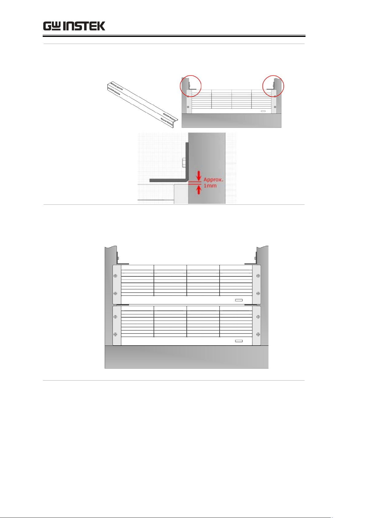
L-shape brackets in the interior side of rack. An approx. 1mm
distance between the bottom o
f brackets and the top of PEL-3211H is
required.
Step 3
Put the 2nd PEL
-3211H onto the L-shape brackets within the rack and,
again,
fasten the 4 screws for side bracket in the front but not tighten
them
fully followed by screwing another group of L-shape brackets
within the interior of rack.
2nd unit installation completion
L-shape
bracket
The L-shape brackets screwed
on the interior side of rack
Approx. 1mm between
bracket and the top of unit

PEL-3000H Series Parallel Assembly Guide
5
Step 4
Repeat the previous steps in order to install
the rest of PEL-3211Hs and
further
install the bracket (GRA-414-3) of PEL-3111H on the upper side
followed by installing the PEL
-3111H onto the top of the bracket.
Assembly completion for 5 units

PEL-3000H Series Parallel Assembly Guide
6
COPPER STICK
ASSEMBLY
Step 1
Assemble the L
-type copper stick (PEL-005) onto the output terminal in
the rear side of each unit as the figur
e below shown.
L-type copper stick assembly
L-type copper sticks assembly completion
Step 2
In accordance with the figure below, assemble the copper sticks
for unit
conjunction followed by fastening the screws in the front of rack tightly.
Copper sticks assembly diagram
Diagram of rear side for copper
sticks assembly

PEL-3000H Series Parallel Assembly Guide
7

PEL-3000H Series Parallel Assembly Guide
8
PARALLEL CABLES
INSTALLATION
Step 1
Install the parallel cables in accord with the
following figure.
Note
The last cable connecting to the last unit cannot be clipp
ed with core. When
only one PEL
-3111H connects to a PEL-3211H (Booster) in parallel, the cable
in the Booster end cannot be clipped with core.

PEL-3000H Series Parallel Assembly Guide
9
CONNECT TO AC
POWER CORD
Step 1
Refer to the figure below; connect the AC power cords for all units to the
pow
er sockets in the rear side individually followed by powering on the
power switch
that is underneath the power socket (─ indicates power ON).
Step 2
Attentively check if the indicator in the front panel of all units lights up
wi
th red color:
I. Master indicator lights up as the figure below:
II. Booster indicator lights up as the figure below (STBY indicator
lights up):

PEL-3000H Series Parallel Assembly Guide
10
SYSTEM IN SERIAL
SETTING
Step 1
Power on the power switch in the Master front panel and the indicator
lights
up in green as figure below shown:
Step 2
Press
Main
> Configure[F5] > Next Manu[F4] in the front panel
followed by selecting “4” for Booster number within Configure page,
which indicates 4 Booster units in parallel. See the ste
ps figures below:
Note
Select Booster number corresponding to the actual Booster numbe
r in parallel.

PEL-3000H Series Parallel Assembly Guide
11
Step 3
Properly confirm if the indicator in the front panel of all PEL
-3211H
(Booster) lights up with LINK in green, which means the software set
ti
ng
connects to Booster appropria
tely. Refer to the figure below.

PEL-3000H Series Parallel Assembly Guide
12
CURRENT SINK
CURRENT DIVISION
CHECKUP
Description
The current sink power of PEL
-3111H and PEL-3211H is 1KW:2KW;
therefore, the ratio of current sink will
always be the exactly 1:2.
E.
g., PEL-3322H (3KW); when current sink is set 30A, Master (PEL-3111H)
will sink current by 10A,
whilst Booster (PEL-3211H) will sink current by
20A.
E.g., PEL
-3955H (9KW); when current sink is set 90A, Master
(PEL
-3111H) will sink current by 10A, whilst the rest of the 4 Booster
(PEL-3211H) will sink current by 20A individually.
Step 1
First disman
tle all of the positive parallel copper sticks and parallel cables
in the rear output terminal of unit.
Step 2
Check the 1st Booster current:
I. Connect the parallel cable to the J2 connector in the rear of
PEL-3111H in one end and the J1 connector in the rear of
PEL-3211H in the other end.
II. Power on both PEL-3111H and the 1st PEL-3211H, while keep
the rest units power-off. Set the unit PEL-3111H as the parallel
mode via the following procedure:
III. Select from the main interface
a. Configure > Next Menu > Parallel > Operation; select: Master
b. Configure > Next Menu > Parallel > Parallel; select: OFF
c. Configure > Next Menu > Parallel > Booster; select: 1

PEL-3000H Series Parallel Assembly Guide
13
IV. Based on the connection method in the figure below, connect
current sink cable to the unit followed by setting current sink
value for unit. Measure the currents from both the current sink
cable of Master positive pole and the current sink cable of Booster
positive pole, via current probe, to validate the accuracy of
currents. The measured current value of Master is supposed to be
1/3 of the set value, whereas the measured current value of
Booster should be 2/3 of the set value.
PEL-3111(H)
-+
Power Supply
+
-
Power ON
Power ON
Power OFF
Power OFF
Power OFF
Current
Probe 1
Current
Probe 2
PEL-3211(H)
PEL-3211(H)
PEL-3211(H)
PEL-3211(H)

PEL-3000H Series Parallel Assembly Guide
14
Step 3
The 2nd Boo
ster current checkup:
I. Connect the parallel cable to the J2 connector in the rear of
PEL-3111H in one end and the J1 connector in the rear of
PEL-3211H in the other end.
II. Power on both PEL-3111H and the 2nd PEL-3211H, while keep
the rest units power-off. Set the unit PEL-3111H as the parallel
mode. The setting procedure is identical to the setting of the 1st
PEL-3211H validation.
III. Based on the connection method in the figure below, connect
current sink cable to the unit followed by setting current sink
value for unit. Measure the currents from both the current sink
cable of Master positive pole and the current sink cable of Booster
positive pole, via current probe, to validate the accuracy of
currents. The measured current value of Master is supposed to be
1/3 of the set value, whereas the measured current value of
Booster should be 2/3 of the set value.
-+
Power Supply
+
-
Power ON
Power OFF
Power ON
Power OFF
Power OFF
Current
Probe 1
Current
Probe 2
PEL-3111(H)
PEL-3211(H)
PEL-3211(H)
PEL-3211(H)
PEL-3211(H)
Step 4
Follow the previou
s steps to validate the 3rd and the 4th Booster
respectively
.
Step 5
The assembly procedure and system
setting are completely finished.
Press
Main
to return back to the main screen and the current sink test
is properly ready to in
itiate.
This manual suits for next models
4
Other GW Instek Industrial Equipment manuals