GWAN HSIAN GHS-V8 User manual

GWAN HSIAN
Inverter
GHS-V8
Instruction Manual
(SENSORLESS VECTOR)
220VClass 3φ 3~60Hp
440VClass 3φ 1~60Hp
Please hand this manual to the end-users. in order to let the inverter to function best.
Thank you.

Preface
Thank your so much to adopt the GHS-V8 multi-function IGBT inverter
GHS-V8 series (hereafter referred as GHS-8V).
GHS-V8 series of general-purpose inverters provide V/f and vector
control as standard features with user-friendly operation. They are the
high-end work of modern power electronics and electro-mechanic drive
technology. Please read this instruction before attempting to install,
operate, maintain, or inspect a GHS-V8 inverter. It is recommended to
keep this manual in secure and convenient place for any future reference.

GWAN HSIAN ELECTRIC&MACHINERY CO.,LTD 1
■ "WARNING" or “ CAUTION"
DANGER!
1. Be sure to turn off the main circuit power before any wiring work is to conduct.
2. Do not touch the circuit or replace any component right after turning off the power
source until the "CHARGE" LED off because of the high voltage still in the
converter. (LED “Charge" lamp indicates that there is still some charge in the
capacitor)
3. Never connect the output terminals U, V, W to AC power supply by mistake.
4. Only authorized personnel should be permitted to perform maintenance, inspections or
parts replacement.
5. Always connect the ground lead E to ground.
6. Never apply high voltage test directly to the components within the inverter. (The
semiconductor devices are vulnerable to high voltage shock).
WARNING
1. Install a (or more) cooling fan to keep the temperature below 45 ℃, when
mounting the inverter in enclosure.
2. Never apply high voltage test directly to the components within the inverter. (The
semiconductor devices are vulnerable to high voltage shock).
3. The CMOS IC on the control board is vulnerable to Electro-Static Discharge. Do not
try to touch the control board.
4. All the parameters of the inverter have been preset at the factory. Do not change the
settings unnecessarily except the case of special application.
CAUTION
1. Prior to installation, operation, and maintenance, read this manual thoroughly and make sure to be
proceeded by qualified professional personnel.
2. Verify if the model types is same as your expectation.
3. Do not install the converter with any damage or missing part.
4. Each inverter shall be attached with QC marking. Do not install the inverter without QC marking.

GWAN HSIAN ELECTRIC&MACHINERY CO.,LTD 2
Table Of Contents
1. GHS-V8 Handling Description --------------------------------------------------------------------------3
1.1 Inspection Procedure upon eceiving---------------------------------------------------------------------3
1.2 Installation Orientation and pace-------------------------------------------------------------------------4
3 Checking and Controlling the Installation Site-----------------------------------------------------------4
1.4 Stock Site (or warehouse) otice---------------------------------------------------------------------------4
1.5 GHS-V8 Inverter Standard
Specification----------------------------------------------------------------5
1.6 Exterior and Mounting imensions------------------------------------------------------------------------7
2. Wiring---------------------------------------------------------------------------------------------------------9
2-1 Standard Connection Diagram--------------------------------------------------------------------------- 9
2-2 Wiring Main Circuit Terminals and Control Circuit Terminals-------------------------------------10
2-3 Wiring between Inverter and Peripheral Devices ----------------------------------------------------12
2-4 Wiring Peripheral Units compatible to main circuit and their precaution items-----------------14
3. Using the LCD Digital Operator-------------------------------------------------------------------------17
3.1 Functions of LCD Digital Operator--------------------------------------------------------------------17
4. Parameter Setting-----------------------------------------------------------------------------------------23
4.1 Frequency Command An- ---------------------------------------------------------------------23
4.2 Parameters That Can be Changed during Running Bn- ----------------------------------24
4.3 Control Parameters Cn- -----------------------------------------------------------------------31
4.4 System Parameters Sn- -------------------------------------------------------------------------72
4.5 Monitoring Parameters Un- -------------------------------------------------------------------89
5. Fault Display and Troubleshooting--------------------------------------------------------------------92
5.1 Error Message and Troubleshooting--------------------------------------------------------------------96
6. Appendix
6.1 List of braking resistor and braking detection module----------------------------------------------96
6.2 AC Reactor-----------------------------------------------------------------------------------------------97
6.3 Noise filter List------------------------------------------------------------------------------------------98
6.4 Physical dimension of digital operator---------------------------------------------------------------100
6.5 LCD Digital Operator Display, Language Selection and Parameter Copy Function setting-101

GWAN HSIAN ELECTRIC&MACHINERY CO.,LTD 3
1.GHS-V8 Handing Description
1-1 Inspection Procedure upon Receiving
Before delivery, every MA7200 inverter has been properly adjusted and has passed a demanding factory
test. After receiving the MA7200 inverter, the customer should follow the procedures listed below:
Verify that the Model Number of the inverter you have received is the same as the Model Number
listed on your purchase order. (Please read the Nameplate)
Observe the condition of the shipping container and report any damage immediately to the
commercial carrier that delivered your inverter.
▓ Inverter Nameplate:
▓Inverter Model Number:
GHS-V8-L 0P7 C
GHS-V8
Series
Operator Types:
E:LED Operator
C:LCD Operator
Capacity (KW)
0P7 0.75KW
1P5 1.5KW
2P2 2.2KW
3P7 3.7KW
5P5 5..5KW
Rated Voltage
L:220V
H:440V
MODE GHS-V8-L0P7C
INPUT AC3PH,200~230V,50/60Hz,6.0 A
OUTPUT AC3PH,0
~
230V,0~400Hz,
9KVA,5.0A
SER.NO. 12345
Output
S
p
ecification
Input
Specification
Model No,.
Series No.

GWAN HSIAN ELECTRIC&MACHINERY CO.,LTD 4
1-2 Installation Orientation and Space
When installing the inverter GHS-V8, always provide the following installation space to allow
normal heat dissipation.
50 mm min.
30 mm min. 30 mm min.
50 mm 以上
(Inlet temp)
-10 ~ + 40 ℃
air
air
120 mm min.
120 mm min.
(a) Horizontal space (b) Vertical space
Figure 1 GHS-V8 Installation orientation and Space
1-3 Checking and Controlling the Installation Site
It is important for the installation site of inverter to achieve proper performance and normal
operating life. Followings are the conditions need to be considered.
Ambient temperature: -10℃ ~ +40 ℃
Free from rain, moisture, and direct sunlight.
Free from harmful mist, gases, liquids, dusts and metallic powder.
Free from excessive oscillation and electromagnetic noise.
If more than 1 inverter are installed in a box, be sure to add a cooling fan or air
conditioner to maintain the air temperature below +45℃。
1-4 Stock Site (or warehouse) Notice:
The inverter, when not used, must be properly placed in the clean location where has or is
free from oil mist and dust
Ambient temperature :-20 to +60oC
relative humidity below 90% RH with no condensation
free from harmful mists, gases, liquids, airborne dusts and metallic particles.
properly packaged on the on the case or table above the ground
not in direct sunlight

GWAN HSIAN ELECTRIC&MACHINERY CO.,LTD 5
1-5 GHS-V8 Inverter Standard Specification
There are 2 voltage class types: 220V class and 440V class.
220V Class
Input Voltage Class 3 phase
GHS-V8-
MODEL 0P7 1P5 2P2 3P7 5P5 7P5 011 015 018 022 030 037 045
HP 1 2 3 5 7.5 10 15 20 25 30 40 50 60 Max. Applicable Motor
Output (CT)* kW 2.2 3.7 5.5 7.5 11 15 18.5 22 30 37 45
Rated Output Capacity (kVA) 4 7.5 10.1 13.7 20.6 27.4 34 41 54 68 78
Rated Output Current (A)* 9.6 17.5 24 32 48 64 80 96 130 160 183
Max. Output Voltage (V) 3 phase 200~230V
Output
Power
Max. Output frequency(Hz) Through parameter setting ( 0 Hz to 400Hz)
Rated Voltage, Frequency 3 Phase 200V~230V, 50/60Hz
Allowable Voltage Fluctuation -15% ~ +10%
Power Source
Allowable Frequency
Fluctuation ±5%
Operation Mode LED operator or LCD operator。
Control Mode Sinusoidal PWM
Frequency Control Range 0.5Hz~400Hz
Frequency Accuracy
(varied with temperature)
Digital Command:
±
0.01%(-10 ~ +40℃)
Analog Command:
±
0.1%, (25
±
10ºC)
Frequency Command
Resolution Digital Command: 0.01Hz Analog Command: 0.06Hz/60Hz
Frequency Output Resolution 0.01Hz
Overload Resistibility (constant torque)150% Rated Current for 60 sec;
(varied torque) 120% rated Current for 60 sec
Frequency Setting Signal DC 0 ~ +10V / 4 ~ 20mA
Acc./Dec. Time 0.0 to 6000 Seconds (Independent Accel/Decel Time Settings)
Voltage-Frequency
Characteristics Adaptable V/f through parameter setting
Regeneration Torque 100%,2%ED,5 秒
Main Control Function Auto Torque Boost, Slip Compensation, Restart After Momentary Power Loss, Energy-Saving, PID Control, RS-485
Communication, Simple PLC Function, Sensorless Vector Control
Control Characteristics
Extra Function Up/Down Operation, 4 Different Sets of Fault Status Record (Including Latest One), Cumulative Power On &
Operation Hour Memory, Energy Savings Function, MODBUS Communication, Multiple-Pulse Output Ports, etc.
Stall Prevention
During Acceleration/Deceleration and Constant Speed Operation
(Current Level can be Selected During Acceleration and Constant Speed Operation. During Deceleration, Stall
Prevention can be Enabled or Disabled)
Instantaneous Overcurrent (OC) 200% of Rated Output Current
Inverter overloads
Protection(OL2) Motor Coasts to Stop after 1 Minute at 150% Rated Output Current
Motor Overload (OL1) Electronic Overload Protection
Over voltage(OV) Motor Coasts to Stop if VDC
>
410V (230V) or VDC
>
820V (460V)
Low voltage(UV) Motor Coasts to Stop if VDC
<
200V (230V) or VDC
<
400V (460V)
Momentary Power Loss
Ride-Through time Motor Coasts to Stop after Momentary Power Loss Lasting
>
15ms
Overheat (OH) Protection by Thermistor
Grounding Protection (GF) Protection by the DC Current Sensor
Protection Function
Charge Indication Lit when the DC Bus Voltage ≧50V
Mechanical Construction Enclosed, Wall-Mounted Type (NEMA-1)
Cooling Forced
Weight(kg) 7.1 7.1 13.1 13.1
Location Indoor (Protected from Corrosive Gases and Dust)
Ambient Temperature +14 to 104oF, -10 to +40ºC (Not Frozen)
Storage Temperature -4 to 140oF, -20 to +60ºC
Humidity Below 90%RH (Non-Condensing)
E
n
v
i
r
o
n
m
e
n
t
a
l
C
o
n
d
i
t
i
o
n
s
Altitude, Vibration Below 3300ft. (1000m), 5.9m/S2 (0.6G), (JISC0911 Standard)
Communication Function RS-485 Installed (MODBUS Protocol)
EMI Meets EN50081-2 (1994) With TECO Specified EMI Filter
EMC Compatibility Meets Pr EN50082-2

GWAN HSIAN ELECTRIC&MACHINERY CO.,LTD 6
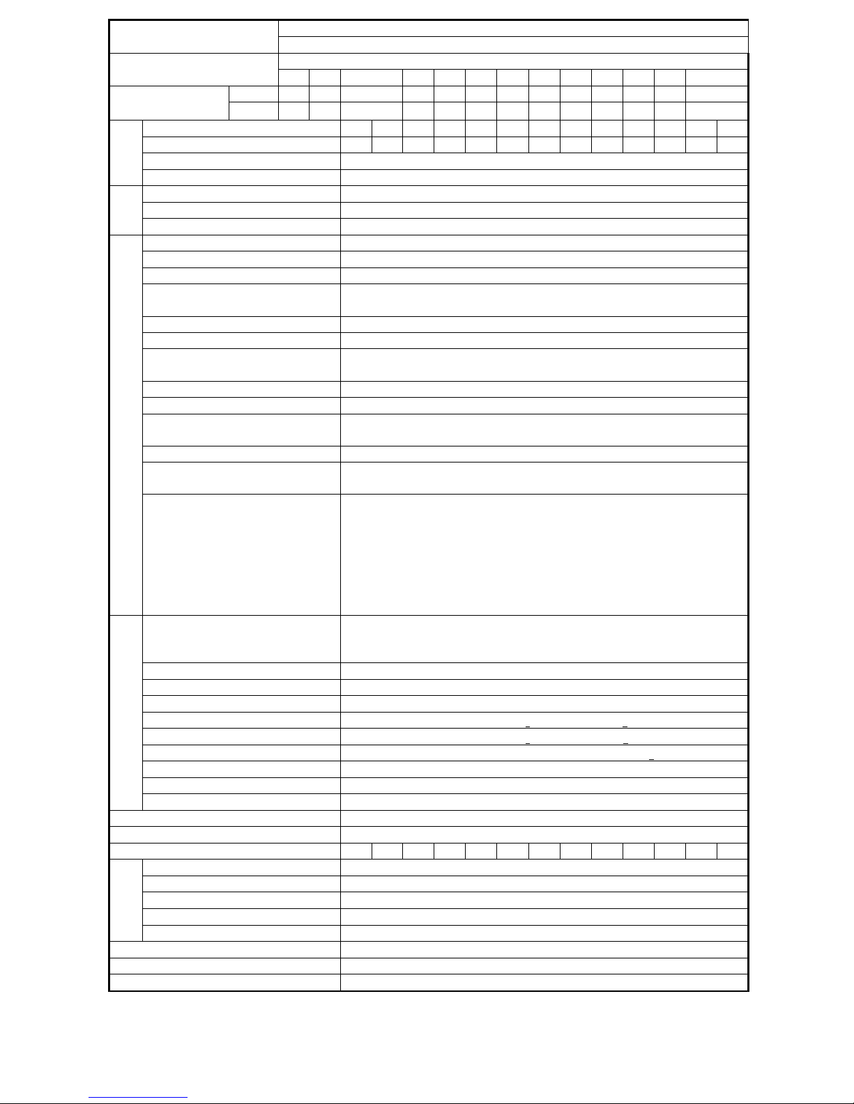
440V Class
Input Voltage Class 3 phase
GHS-V8-
MODEL 0P7 1P5 2P2 3P7 5P5 7P5 011 015 018 022 030 037 045
HP 1 2 3 5 7.5 10 15 20 25 30 40 50 60
Max. Applicable
Motor Output (CT)* kW 0.75 1.5 2.2 3.7 5.5 7.5 11 15 18.5 22 30 37 45
Rated Output Capacity (kVA) 2.1 2.7 4 7.5 10.1 13.7 20.6 27.4 34 41 54 68 82
Rated Output Current (A)* 2.6 4.0 4.8 8 12 16 24 32 40 48 64 80 196
Max. Output Voltage (V) 3 phase 200~230V
Output Power
Max. Output frequency(Hz) Through parameter setting ( 0 Hz to 400Hz)
Rated Voltage, Frequency 3 Phase 200V~230V, 50/60Hz
Allowable Voltage Fluctuation -15% ~ +10%
Power
Source
Allowable Frequency Fluctuation ±5%
Operation Mode LED operator or LCD operator。
Control Mode Sinusoidal PWM
Frequency Control Range 0.5Hz~400Hz
Frequency Accuracy
(varied with temperature)
Digital Command:
±
0.01%(-10 ~ +40℃)
Analog Command:
±
0.1%, (25
±
10ºC)
Frequency Command Resolution Digital Command: 0.01Hz Analog Command: 0.06Hz/60Hz
Frequency Output Resolution 0.01Hz
Overload Resistibility (constant torque)150% Rated Current for 60 sec;
(varied torque) 120% rated Current for 60 sec
Frequency Setting Signal DC 0 ~ +10V / 4 ~ 20mA
Acc./Dec. Time 0.0 to 6000 Seconds (Independent Accel/Decel Time Settings)
Voltage-Frequency
Characteristics Adaptable V/f through parameter setting
Regeneration Torque 100%,2%ED,5 秒
Main Control Function Auto Torque Boost, Slip Compensation, Restart After Momentary Power Loss, Energy-Saving, PID
Control, RS-485 Communication, Simple PLC Function, Sensorless Vector Control
Control Characteristics
Extra Function
Up/Down Operation, 4 Different Sets of Fault Status Record (Including Latest One), Cumulative
Power On & Operation Hour Memory, Energy Savings Function, MODBUS Communication,
Multiple-Pulse Output Ports, etc.
Stall Prevention
During Acceleration/Deceleration and Constant Speed Operation
(Current Level can be Selected During Acceleration and Constant Speed Operation. During
Deceleration, Stall Prevention can be Enabled or Disabled)
Instantaneous Overcurrent (OC) 200% of Rated Output Current
Inverter overloads Protection(OL2) Motor Coasts to Stop after 1 Minute at 150% Rated Output Current
Motor Overload (OL1) Electronic Overload Protection
Over voltage(OV) Motor Coasts to Stop if VDC
>
410V (230V) or VDC
>
820V (460V)
Low voltage(UV) Motor Coasts to Stop if VDC
<
200V (230V) or VDC
<
400V (460V)
Momentary Power Loss Ride-Through time Motor Coasts to Stop after Momentary Power Loss Lasting
>
15ms
Overheat (OH) Protection by Thermistor
Grounding Protection (GF) Protection by the DC Current Sensor
Protection Function
Charge Indication Lit when the DC Bus Voltage ≧50V
Mechanical Construction Enclosed, Wall-Mounted Type (NEMA-1)
Cooling Forced
Weight(kg) 7.1 7.1 13.1 13.1
Location Indoor (Protected from Corrosive Gases and Dust)
Ambient Temperature +14 to 104oF, -10 to +40ºC (Not Frozen)
Storage Temperature -4 to 140oF, -20 to +60ºC
Humidity Below 90%RH (Non-Condensing)
Environmental
Conditions
Altitude, Vibration Below 3300ft. (1000m), 5.9m/S2 (0.6G), (JISC0911 Standard)
Communication Function RS-485 Installed (MODBUS Protocol)
EMI Meets EN50081-2 (1994) With TECO Specified EMI Filter
EMC Compatibility Meets Pr EN50082-2

GWAN HSIAN ELECTRIC&MACHINERY CO.,LTD 7
1- 6 Dimension
(A) Standard dimension: 220V/440V 1-5HP
Figure 2(A)
Mounting
Dimensions (in.) External Dimensions
(in.)
Voltage
Max. Applicable
Motor Output
(HP)/KW
W H H2 D W1 H1 D
Approx.
Mass
(lbs.) /(kg)
1HP╱0.75KW
2HP╱1.5KW
3HP╱2.2KW
220V
3ψ 5HP╱3.7KW 133 260 6 5 145 273 170 3.2
1HP╱0.75KW
2HP╱1.5KW 133 260 6 5 145 273 170 3.2
3HP╱2.2KW
440V
3ψ
5HP╱3.7KW 133 260 6 5 145 273 170 3.2

GWAN HSIAN ELECTRIC&MACHINERY CO.,LTD 8
Figure 2(B)
Mounting
Dimensions (in.) External Dimensions
(in.)
Voltage
Max. Applicable
Motor Output
(HP)/KW
W H H2 d W1 H1 D
Approx.
Mass
(lbs.) /(kg)
7.5HP/5.5KW
10HP/7.5KW 120 300 7.5 7 204 315 196 7.1
15HP/11KW
220V
440V
3ψ 20HP/15KW 140 394 8 8 244 410 202 13.1
25HP/18.5KW
30HP/22KW
40HP/30KW
50HP/37KW
220V
3ψ
60HP/45KW
25HP/18.5KW
30HP/22KW
40HP/30KW
50HP/37KW
440V
3ψ
60HP/45KW
(B) 220V/440V 5.5KW above

GWAN HSIAN ELECTRIC&MACHINERY CO.,LTD 9
2 wgring
2-1 Standard Connection Diagram
The standard connection diagram of GHS-V8 is shown in Figure 3. The sign indicates the
power circuit terminal and the sign indicates control circuit terminal. The terminal arrangement for
inverter (<15kW) is shown below.
P/B1 B2
Braking Resistor
R
S
T
MCB
1
2
3
4
5
6
7
8
Multi-Function
Contact Input
NFB
Shield Sheath
E
GND Analog Signal
Common
24VG Sink Common
+12V Power Supply for
Speed Reference (+12V, 20 mA max. )
AIN Master Speed
Reference
2KΩ, 1/2W
VIN Master Speed
Reference ( 20KΩ )
AUX Multi-Function
Analog Input
2KΩ
1/2W
FWD/Stop
REV/Stop
External Fault
Fault Reset
Multi-Step
Speed Reference1
Jog Command
External BaseBlock
Factory Preset External Frequency Command
P
P
P
0 ~ +10V
4 ~ 20 mA
0 ~ +10V
0V
( 250Ω )
P
AO1
V
WIM
Grounding Lead (<100 Ω)
GND
AO2
R1A
R1
B
R1
C
Multi-Function Contact Output 1
(250V AC, <1A
30V DC, <1A)
DO1
DOG
Multi-Function Output 1
(OPEN COLLECTOR 48V,
50mA)
RS-485 Communication Port
S(+)
S(-)
Analog Monitor 1, 2
(DC 0 ~ 10 V)
U
Power
Source
Shielded wire Shielded Twisted Wire
Note:
R2A
R2
C
Multi-Function Contact Output 2
(250V AC, <1A
30V DC, <1A )
(20KΩ )
Analog Output 1
E
+24V Source Common
+24V
Multi-Step
Speed Reference2
Analog Output 2
1 2 3
4
5678
AO1 GND DO1 S(+) R1A R1B R1C R2A R2C
E 24V 24VG +12V AIN VIN AUX AO2 GND DOG E S(-)
Figure 3:GHS-V8standard connection diagram

GWAN HSIAN ELECTRIC&MACHINERY CO.,LTD 10
2-2Description of Terminal Function
Table 1 Main circuit terminals
Terminal Terminal Function
R/L1
S/L2
T/L3
Main circuit input power supply
(For single phase power supply, please use R/L1, S/L2 as input terminal)
B1/P
B2/R
B2
B1/P, B2: External braking resistor
B1/P, : DC power supply input
U/T1
V/T2
W/T3
Inverter output
E Grounding lead (3rd type grounding)
Main circuit terminal block configuration
. 220V/440V 10HP below
. 220V/440V 15HP~20HP
. 220V/440V 25HP~60HP

GWAN HSIAN ELECTRIC&MACHINERY CO.,LTD 11
Table 2 Control circuit terminals
Terminals Functions
1 Forward Operation – Stop Signal
2 Reverse Operation – Stop Signal
3 External Fault Input
4 Fault Reset
5
6
7
8
Multifunction Input Terminal: 3 –Wire Operation, Local/Remote Control,
Multi-Speed Select, FWD/Rev ACC/DEC Choice, ACC/DEC Halting, Base
Block, Overheat Warn, PID Control, DC Braking, Speed Search, Up/Down
Function, External Fault, Timer function, Multifunction Analog Input Setting.
24VG
Digital Signal Ground
Sink Common Point (Locate the short jumper of JP1 in 1-2 position) (NPN)
24V
Digital Signal Ground
Sink Common Point (Locate the short jumper of JP1 in 2-3 position)
E Connection to Shield Signal Lead
+12V Power Supply for External Device
VIN Master speed Voltage Reference (0-10V)
AIN Master speed Current Reference (4-20mA)
AUX
Auxiliary Analog Input:
Auxiliary Frequency Command, Frequency Gain, Frequency Bias,
Overtorque Detection, Output Voltage Bias, ACC/DEC Ramp, DC-Brake
Current, Stall Prevention Current Level during Running Mode, PID Control,
Lower-Bound of Frequency Command, Frequency-Jump-4, etc…
GND Analog Signal Common
AO1
AO2
Analog Multi-Function Output Port:
Frequency Command, Output Frequency, Output Current, Output Voltage,
DC Voltage, PID Controlled Value, Analog Command Input of VIN,AIN or
AUX.
GND Common Lead for Analog Port
R1A Relay Contact R1 Output A
R1B Relay Contact R2 Output B
R1C Relay Contact R1 Common
R2A Relay Contact R2 Output A
R2C Relay Contact R2 Common
DO1 Open-collector transistor's
output
DOG Common terminal of open
collector transistor
Digital Multi-Function Output:
During-Running, Zero-Speed, Agreed-frequency,
Agree-Frequency-Setting, Frequency Output,
Invert-Operation-Ready,
Under-voltage-Detections, Base Block, Frequency
Command, Overtorque Detection, Frequency
Command Invalid, Fault, Undervoltage, Overheat,
Motor overload, Inverter Overload, During-Retry,
Communication-Fault, Timer-Function-Output
S(+)
S(-) RS-485 Port
Caution
Use the control circuit terminals VIN, AIN according to the setting of Sn-24.
The maximum output current at terminal (+15V or +12V) is 20mA.
The multi-function analog output terminals AO1, AO2 is a dedicated output for a
frequency meter, ammeter, etc. Do not use these 2 analog outputs for feedback
control or for any other control purpose.

GWAN HSIAN ELECTRIC&MACHINERY CO.,LTD 12
2-3 Wiring between the inverter and peripheral devices and notice
1. Always use ground leads that comply with AWG standards and make sure the
length is as short as possible. (refer Table 3)
2. Always check the output voltage and maximum current of the power source if it
can handle the required power.
3. Never connect AC main circuit power supply to output terminals U/V1, V/T2 and
W/T3.
4. Make sure all the screws properly tightened/fixed together
5. The MCCB (Molded-Case Circuit Breaker) should be installed between the AC
power supply and input terminals R/L1-S/L2-T/L3 on the GHS-V8 inverter.
The user can make his own decision whether or not to install a MC (Magnetic
Contactor) block. When a ground fault interrupter is used, select the one with
no influence for high frequency. Setting current should be 200mA or above and
the operating time at 0.1 second or longer to avoid false triggering.
Grounding.
1. Always use the ground terminal (E) with a ground resistance of less than 100 ohm.
2. Never ground GHS-V8 with other devices such as welding machines, motors, and
other large-current electrical equipment, or ground pole. Run the ground lead in
separate conduit from leads for large-current electrical equipment.
3.Always use ground leads that comply with AWG standards and make sure the length
is as short as possible.
4.When using several GHS-V8 inverters side by side, it is preferable to ground each
unit separately to ground poles. However, connecting all the ground terminals of
GHS-V8 in parallel while only grounding one of the GHS-V8's to the ground pole is
also permissible. Be sure not to form a loop with the ground leads.
(a) Correct (b) Correct (c) Not Acceptable
Wiring Main Circuit Terminals:
1. Phase rotation of input terminals R/L1, S/L2, T/L3 is available in either
direction. (Clockwise and Counter-Clockwise)
2. Never connect AC main circuit power supply to output terminals U/V1, V/T2 and
W/T3.
3. Connect the output terminals U/T1, V/T2, W/T3 to motor lead wires U/T1, V/T2,
and W/T3, respectively.
4. Check that the motor rotates forward with the forward run source. Switch over any
2 of the output terminals to each other and reconnect if the motor rotates in reverse
with the forward run source.
5. Never connect power factor correction capacitors or input side EMI/RFI filters to
GHS-V8 output.

GWAN HSIAN ELECTRIC&MACHINERY CO.,LTD 13
Wiring Control Circuit terminals:
1. After turning OFF the main circuit power supply, do not touch or change any
circuit components until the LED “CHARGE" lamp has extinguished. (LED
“Charge" lamp indicates that there is still some charge in the capacitor).
2. Never do wiring work or take apart the connectors in the inverter while the power
is still on.
3. Separate the control circuit leads from the main circuit leads (R/L1, S/L2, T/L3,
U/T1, V/T2, W/T3) and other power cables to prevent erroneous operation caused
by noise interference. When necessary, try to have main-circuit wire and control
circuit wire cross in 90 degree to avoid signal interference.
4. Separate the control circuit terminals leads RA-RB-RC (R1A-R2B-R2C) (contact
output) from leads to terminals ~, A01, A02, GND, DO1, DO2 (R2A-R2C),
DOG and 15V, VIN, AIN, AUX, GND, IP12, IG12, A (+), A (-).
5. Use twisted-pair or shielded twisted-pair cables for control circuits to prevent
operating faults. Process the cable ends as shown in Figure 3. The maximum wiring
distance should not exceed 150 feet.
6. When the digital multi-function output terminals connect serially to an external
relay, an anti-parallel freewheeling diode should be applied at both ends of the
relay.
7. Never apply high voltage test directly to the components within the inverter. (The
semiconductor devices are vulnerable to high voltage shock).
8. The CMOS IC on the control board is vulnerable to Electro-Static Discharge. Do
not try to touch the control board.
9. If Sn-03 is set to 3,5,7 for 2-wire operation or if Sn-03 is set to 4,6,8 for 3-wire
operation, the parameter settings will return to factory default settings. (Except for
parameter settings in Sn-01 and Sn-02, they will remain at their modified settings).
If the inverter is initially operated in 3-wire mode (Sn-03= 4,6,8), the motor will
rotate in CCW direction after setting has been changed to 2-wire mode. (Sn-03=
3,5,7). Be sure that terminals 1 and 2 are OPEN to ensure protection against
personal harm or injury and to prevent any potential damage to machines.
10. If the cable between the inverter and the motor is excessively long, the
high-frequency leakage current will increase causing the inverter output current to
increase as well. This may affect peripheral devices. To prevent this, adjust the
carrier frequency as shown below.
Cable Length < 100ft. 100-165ft. 166-328ft.
>
329ft.
Carrier Frequency
(Cn-34)
15kHz max
(Cn-34=6)
10kHz max
(Cn-34=4)
5kHz max
(Cn-34=2)
2.5kHz
(Cn-34=1)

GWAN HSIAN ELECTRIC&MACHINERY CO.,LTD 14
2-4 Wiring Main Circuit and Notice
The user should decide if it is necessary to install the non-fusible-breaker (NFB) and electromagnetic
contactor block (MCB) between the AC source and the R, S, T input terminals. To protect against the
false triggering of leakage-current , the user should install a leakage current breaker with amperage
sensitivity ≧ 200 mA and operation time ≧ 0.1 sec.
Table 3 (a) 220V SERIES
GHS-V8 Model Wire Size(mm2)
Rated Rated current
Applicable
Power
Rating
HP(KW)
[NOTE1] KVA (A)
Main
Circuit*2
[NOTE2]
Ground
Wire
E[G]
Control
Wire*3
[NOTE3]
NFB
[NOTE4] MCB
[NOTE4]
1(0.75) 2 4.8 2~5.5 2~5.5 0.5~2 TO-50E
(15A) C-11L
2(1.5) 2.7 6.4 2~5.5 3.5~5.5 0.5~2 TO-50E
(20A) C-11L
3(2.2) 4 9.6 3.5~5.5 3.5~5.5 0.5~2 TO-50E
(20A) C-11L
5(3.7) 7.5 17.5 5.5 5.5 0.5~2 TO-50E
(30A) C-16L
7.5(5.5) 10.1 24 8 5.5~8 0.5~2 TO-100S
(50A) C-18L
10(7.5) 13.7 32 8 5.5~8 0.5~2 TO-100S
(60A) C-25L
15(11) 20.6 48 22 8 0.5~2 TO-100S
(100A) C-50L
20(15) 27.4 64 30 8 0.5~2 TO-100S
(100A) C-65L
25(18.5) 34 80 30 14 0.5~2 TO-225S
(150A) C-80G
30(22) 41 96 38 14 0.5~2 TO-225S
(175A) C-100L
40(30) 54 130 100 22 0.5~2 TO-225E
(175A) C-125G
(170A)
50(37) 68 160 60*2P 22 0.5~2 TO-225E
(200A) C-125G
(200A)
60(45) 78 183 60*2P 22 0.5~2 TO-225E
(200A) C-125G
(235A)

GWAN HSIAN ELECTRIC&MACHINERY CO.,LTD 15
Table 3 (b) 440V SERIES
GHS-V8 Model Wire Size(mm2)
Rated Rated current
Applicable
Power
Rating
HP(KW)
[NOTE1] KVA (A) Main
circuit
[NOTE2]
Ground
connectio
n wire
E[G]
Control wire*3
[NOTE3]
NFB
[NOTE4] MCB
[NOTE4]
1(0.75) 2.1 2.6 2~5.5 2~5.5 0.5~2 TO-50E
(15A) C-11L
2(1.5) 2.7 4.0 2~5.5 3.5~5.5 0.5~2 TO-50E
(15A) C-11L
3(2.2) 4 4.8 2~5.5 3.5~5.5 0.5~2 TO-50E
(15A) C-11L
5(3.7) 7.5 8 3.5~5.5 5.5 0.5~2 TO-50E
(15A) C-18L
7.5(5.5) 10.1 12 3.5~5.5 5.5~8 0.5~2 TO-100S
(20A) C-18L
10(7.5) 13.7 16 5.5 5.5~8 0.5~2 TO-100S
(30A) C-25L
15(11) 20.6 24 8~14 8 0.5~2 TO-100S
(50A) C-25L
20(15) 27.4 32 8~14 8 0.5~2 TO-100S
(60A) C-35L
25(18.5) 34 40 14 14 0.5~2 TO-225S
(75A) C-50G
30(22) 41 48 22 14 0.5~2 TO-225S
(100A) C-50L
40(30) 54 64 22 22 0.5~2 TO-225E
(100A) C-65G
50(37) 68 80 38 22 0.5~2 TO-225E
(150A) C-80L
60(45) 82 196 50 22 0.5~2 TO-225E
(175A)
C-100L(17
0A)
(170)
* 1:It is assumed constant torque load。
* 2:The main circuit has terminals of R(L1)、S(L2)、T(L3)、U(T1)、V(T2)、W(T3)、P/B1、
Θ 、B2、
* 3 :The control wire is the wire led to the pin terminals of control board.
* 4 : In Table 3 ,the specified Part No. of NFB and MCB are the item No. of the products of
(Taian). The customer can use the same rating of similar products from other sources. To
decrease the noise interference, be sure to add R-C surge suppressor(0.1uf/1000VDC,10Ω/5W)
at the 2 terminals of coils of electromagnetic contractor.

GWAN HSIAN ELECTRIC&MACHINERY CO.,LTD 16
Example of connection between the GHS-V8 and typical peripheral devices are shown as below.
■ Power supply switch (NFB) and earth leakage breaker
‧ Refer to Table3, choose the power supply switch of proper current
rating.
‧ Do not use the NFB as the switch that the inverter is used to control
the running or stop of motor.
‧ When the earth leakage breaker installed to protect the leakage
current fault, be sure the earth leakage breaker has the sensitivity
amperage ≧ 200 mA and operation time ≧ 0.1 sec to avoid
false-triggering.
■ Electromagnetic contactor
In normal operation, you don't need an electromagnetic contactor.
However, you need to install an electromagnetic contactor
while in the case of sequence control through the external device or
automatically re-start after power outage.
Do not use the electromagnetic contactor as the switch that control
the operation of running or stop.
■ AC reactor
‧ The AC-Side reactor on the input AC side can be improve the power
factor and suppress the surge current.
■ Input noise filter
‧ GHS-V8 will comply with the EN55011 Class A regulation if an
input noise filter is used。
‧ Please consult with the selection guide on Appendix "Noise filter
at power supply side"
■ Inverter
‧ Input power supply can be connected to any terminals or terminals
block.
‧ Please connect the ground terminal to the site ground securely.
■ Output noise filter
‧ Install the noise filter to eliminate noise transmitted through the power
line and the inverter so that the electromagnetic conductive noise and
inductive noise can be reduced to an acceptable level.
‧ Please consult with the selection guide on Appendix“zero-phase
noise filter"
‧
■ Induction Motor
‧ If one inverter is drive more than one motor, the inverter's rated
current should be much greater than the sum of total current of
motors while in operation.
‧ The inverter and the motor should connect to the ground separatedly.

GWAN HSIAN ELECTRIC&MACHINERY CO.,LTD 17
3. Using the LED Digital Operator
3.1 Functions of LED Digital Operator
The digital Operator has 2 modes: DRIVE mode and PRGM mode. When the
inverter is stopped, DRIVE mode or PRGM mode can be selected by pressing the key
PRGM
DRIVE
. In
DRIVE mode, the operation is enabled. In PRGM mode, the parameter settings for operation can be
changed but the operation is not enabled. The component names and functions are shown below:
RUN
PRGM
DRIVE DSPL
EDIT
ENTER
DRIVE FWD REV REMOTE
SEQ REF
FWD
REV
JOG
SEQ:lit when run command come from control circuit terminal or
RS-485 port is enabled
REF:lit when frequency reference come from control circuit terminal
or RS-485 port is enabled
LED display
Keypad (function as below)
RESET
F60.00
DRIVE:lit when in DRIVE
mode
FWD: lit when a forward run
command is input
REV: lit when a reverse run
command is input
Indicator of
operation
STOP
DIGITAL OPERATOR
TMCA-V8LED
Figure LED Digital Operator

GWAN HSIAN ELECTRIC&MACHINERY CO.,LTD 18
Key' function Table 4
Key Name Function
PRGM
DRIVE
PRGM/DRIVE
Key Switch between operation (PRGM) and operation (DRIVE)
DSPL
DSPL Key Display operation status
JOG
JOG Key Enable jog operation from LED digital operator in operation
(DRIVE)
FWD
REV
FWD/REV Key Select the rotation direction from LED digital operator.
RESET
SHIFT/RESET
Key Set the number of digital for user constant settings. Also It
acts as the `RESET' key when a fault has occurred.
Increment Key Select the menu items, groups, functions and user constant
name, and increment set values.
Decrement Key Select the menu items, groups, functions and user constant
name, and decrement set values.
EDIT
ENTER
EDIT/ENTER Key Select the menu items, groups, functions and user constant
name, and set values (EDIT). After finishing the above
action, press the key.
RUN
RUN Key Start inverter operation in (Drive) mode when the digital
operator is used. The LED will light.
STOP
STOP Key Stop inverter operation from LED digital operator. The key
can be enabled or disabled by setting a constant (Sn-07)
when operation from the control circuit terminal
STOP RUN
Output frequency
Frequency
command
On Off
RUN STOP STOP
RUN indicator
STOP indicator
Blinking
Frequency
command
Table of contents