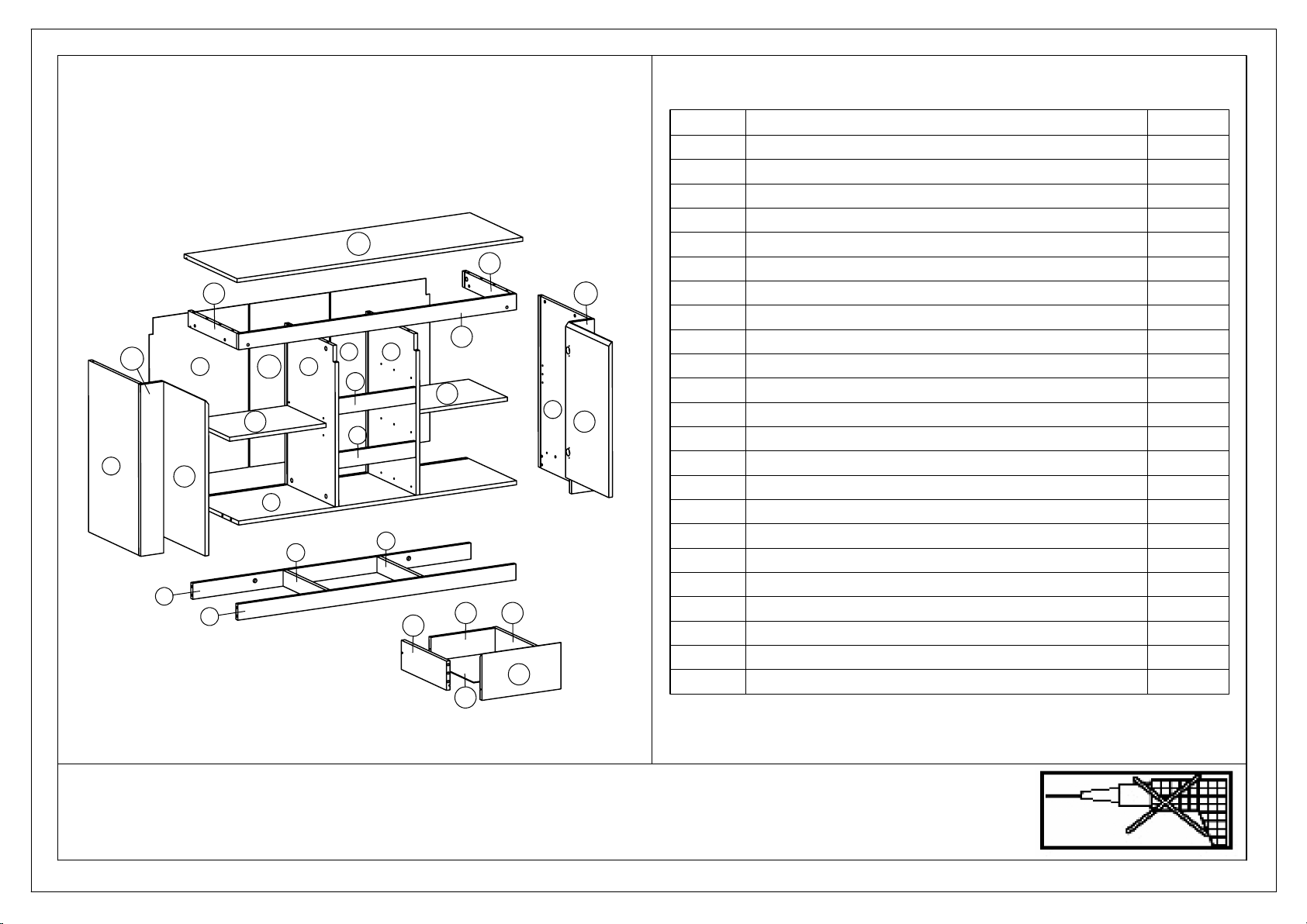
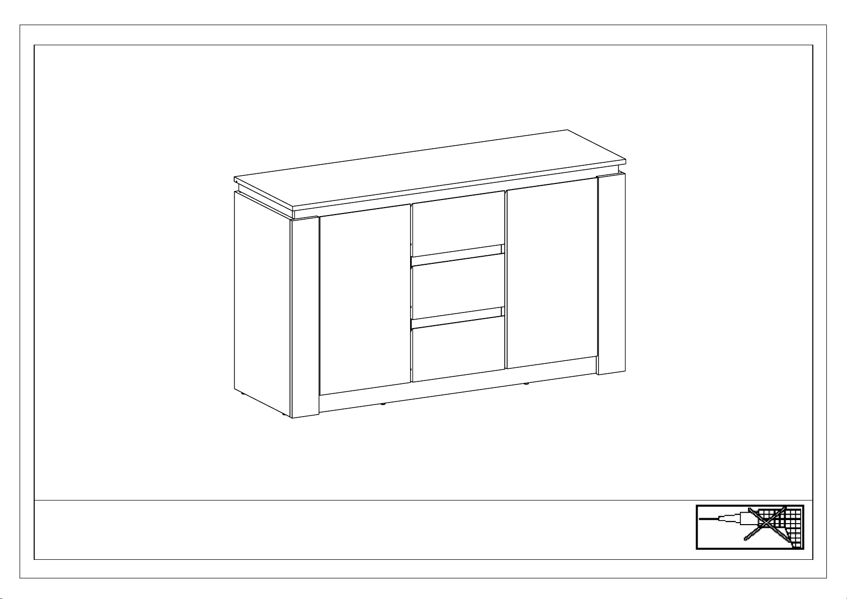
GWF CANYON SIDEBOARD User manual

CANYON SIDEBOARD
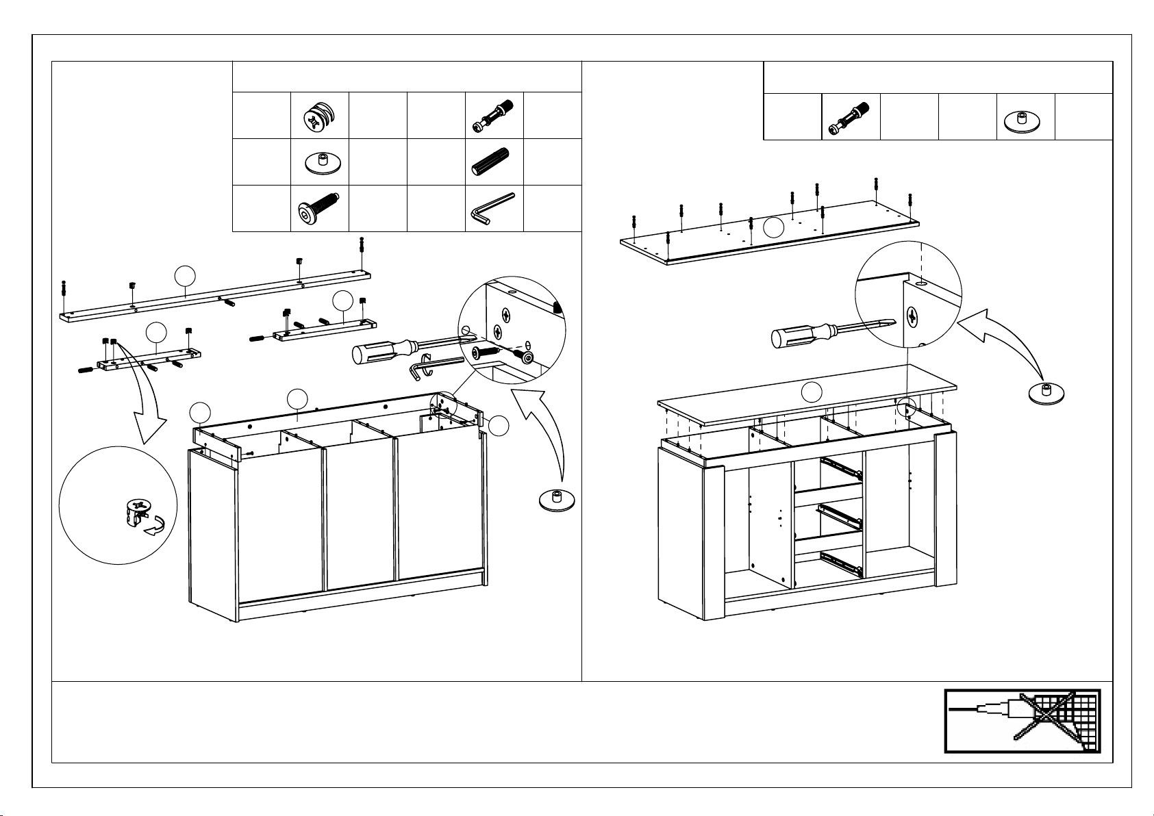
ASSEMBLY INSTRUCTIONS
IMPORTANT
PLEASE READ BEFORE YOU CONTINUE FURTHER
WARNING AND INSTRUCTIONS
GENERIC
IMPORTANT: RETAIN THESE INSTRUCTIONS FOR FUTURE REFERENCE.
•
DUE TO THE SIZE OF THIS PRODUCT WE RECOMMEND THAT IT IS ASSEMBLED IN THE
•
ROOM INTENDED FOR USE.
WHEN YOU ARE READY TO START,MAKE SURE THAT YOU HAVE THE RIGHT TOOLS,
•
PLENTY OF SPACE AND A CLEAN, DRY AREA FOR ASSEMBLY.
UNWRAP ALL PACKAGING MATERIALS AND PLACE THE COMPONENTS ON TOP OF
•
THE CARTON BOX OR ON A CLEAN FLOOR TO PREVENT IT FROM SCRATCHING.
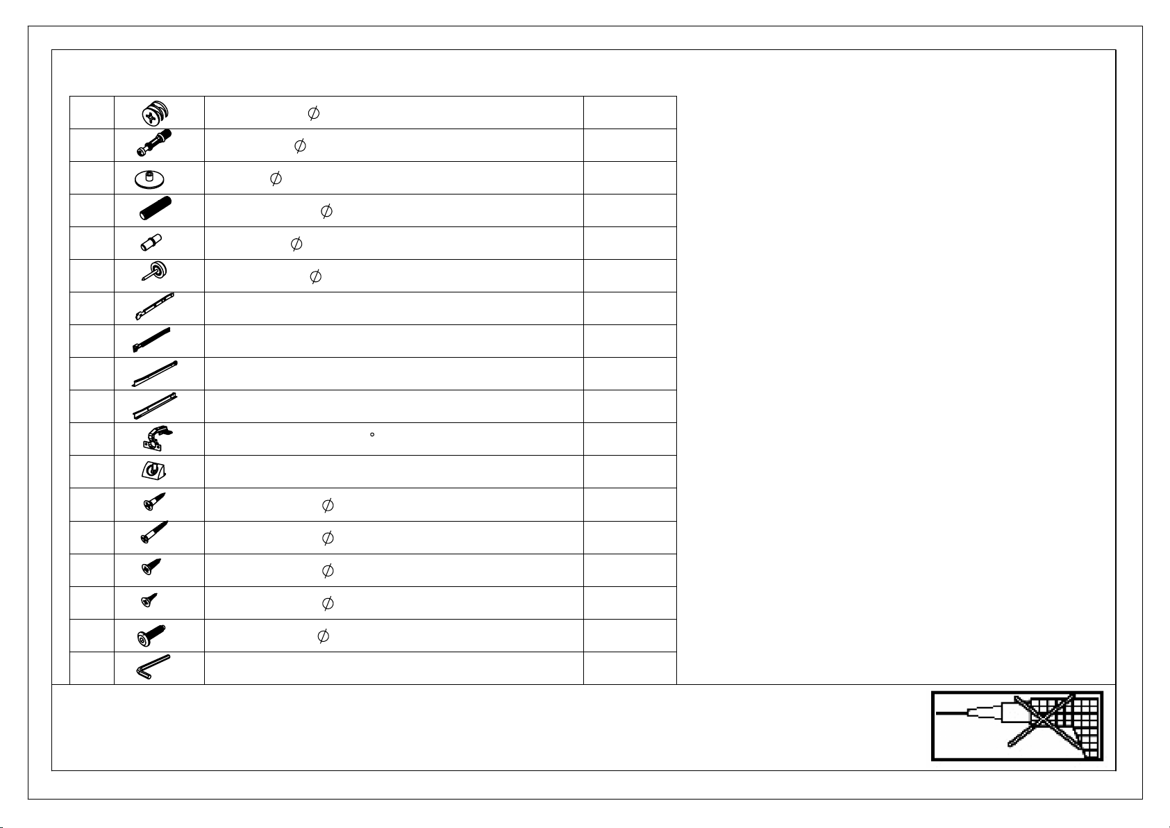
CHECK THE PACK AND MAKE SURE YOU HAVE ALL THE PARTS LISTED.
•
ENSURE THAT THIS PRODUCT IS FULLY ASSEMBLED AS ILLUSTRATED BEFORE USE.
•
TOOLS NOT INCLUDED.
•
CHECK ALL SCREWS OR BOLTS ARE TIGHTENED AND INSPECT REGULARLY.
•
THIS PRODUCT SHOULD ONLY BE USED ON FIRM,LEVEL GROUND.
•
KEEP SMALL PART OUT OF REACH OF CHILDREN.
•
MAKE SURE THE LEGS REMAIN IN CONTACT WITH THE GROUND.
•
DO NOT USE POWER TOOLS TO CONSTRUCT THIS PRODUCT.
•
DO NOT TIGHTEN SCREWS UNTIL FULLY ASSEMBLED.
•
DO NOT OVER TIGHTEN SCREWS OR BOLTS.
•
DO NOT USE THIS PRODUCT IF PARTS ARE MISSING, DAMAGE OR WORN.
•
DO NOT SIT AND STAND ON THE PRODUCT.
•
TO CLEAN WIPE WITH A SPONGE AND WARM SOAPY WATER.DO NOT USE SOLVENT
•
BASED CLEANERS OR DETERGENTS AS THEY CAN BLEACH OR DAMAGE THE PRODUCT.
NEVER USE SCOURERS, ABRASIVES OR CHEMICAL CLEANERS.
•
PAGE 1 OF 10

(Screwdriver not provided)
Use a flat blade screwdriver to
tighten the cam nuts.A quarter
turn clockwise is all that is needed.
This is how a cam nut works...
The head of the bolt goes into the wide mouth of the cam nut.
You then turn the nut so the narrow part closes over the bolt.
TWO PERSONS REQUIRED TO ASSEMBLE THIS PRODUCT
1.Please check that you have all the parts listed before you start
assembling.If you do find that something is missing,do not continue
assembly.Please contact your supplier immediately.
2. Lay out all of the components on a soft surface as if you were preparing
to do a jigsaw puzzle.
3. Separate and identify each component from the hardware pack and rest
each one in its proper location before fastening.
PAGE 2 OF 10

16
5
5
66
4
1
3
2
2
22
22 7
8
11
12 9
9 10
13
14
15
1718
19
20
21
23
24
3x
A
15x12 MM CAM NUT
20 PCS
B
6.5x36.5 MM CAM BOLT
20 PCS
C
18x5 MM MINIFIX COVER CAP
20 PCS
D
8x32 MM DOWEL
16 PCS
E
13x25 MM SCREW
16 PCS
F
14.5x19.5 MM NAILS
8 PCS
G
4 MM ALLEN KEYS 1 PC
10
MIDDLE BACK PANEL
1 PC
11
FRONT RIGHT PANEL
1 PC
12
FRONT LEFT PANEL
1 PC
13
TOP FRONT PLINTH
1 PC
14
TOP RIGHT PLINTH
1 PC
15
TOP LEFT PLINTH
1 PC
16
TOP PANEL
1 PC
17
RIGHT SIDE DRAWER
3 PCS
18
BACK DRAWER
3 PCS
19
LEFT SIDE DRAWER
3 PCS
20
BOTTOM DRAWER
3 PCS
21
HEAD DRAWER
3 PCS
22
SHELF PANEL
2 PCS
23
RIGHT DOOR
1PC
24
LEFT DOOR
1PC
PAGE 3 OF 10
PARTS LIST
THE USE OF POWER TOOLS TO ASSEMBLE THIS PRODUCT WILL INVALIDATE
ANY CLAIM AND MAY DAMAGE THIS PRODUCT MAKING IT UNSAFE
1
MIDDLE RIGHT PANEL
1 PC
2
BACK PLINTH HEAD DRAWER
2 PCS
3
MIDDLE LEFT PANEL
1 PC
4
BOTTOM PANEL
1 PC
5
BOTTOM PLINTH
2 PCS
6
MIDDLE BOTTOM PLINTH
2 PCS
7
RIGHT SIDE PANEL
1 PC
8
LEFT SIDE PANEL
1 PC
9
BACK RIGHT LEFT PANEL
2 PCS

G
OUTSIDE RIGHT DRAWER RUNNERS L=350 MM
3 PCS
H
OUTSIDE LEFT DRAWER RUNNERS L=350 MM
3 PCS
I
INSIDE RIGHT DRAWER RUNNERS L=350 MM
3 PCS
J
INSIDE LEFT DRAWER RUNNERS L=350 MM
3 PCS
K
90
HINGES
4 PCS
L
14x13x9 MM STOPER
22 PCS
M
5x16 MM SCREW
22 PCS
N
7x32 MM SCREW
6 PCS
O
6x13 MM SCREW
30 PCS
P
8x13 MM SCREW
16 PCS
Q
13x25 MM SCREW
6 PCS
R
ALLEN KEY
1 PC
PAGE 4 OF 10
THE USE OF POWER TOOLS TO ASSEMBLE THIS PRODUCT WILL INVALIDATE
ANY CLAIM AND MAY DAMAGE THIS PRODUCT MAKING IT UNSAFE
HARDWARE LIST
A
15x12 MM CAM NUT
36 PCS
B
6.5x36.5 MM CAM BOLT
36 PCS
C
18x5 MM COVER CAP
36 PCS
D
8x32 MM DOWEL
67 PCS
E
5x12 MM SHELF SUPPORT
8 PCS
F
14.5x19.5 MM NAILS
8 PCS

1
OOO
O
O
O
OOO
DD
DD
G
GG
A
A
A
A
2
2x
D
D
DD
3
1
2
2
Arrow to point in
the direction of
the hole
Arrow to point in
the direction of
the hole
3
OOO
OOO
OOO
DD
D
D
HHH
A
A
A
A
DD
DD
B
B
B
B
4
B
B
B
B
A
A
A
A
5
2x
D
D
D
DD
A
A
F
F
6
2x
D
D
DD
5
5
4
6
6
Arrow to point in
the direction of
the hole
AS
C
Arrow to point in
the direction of
the hole
When inserting the cam nuts, rotate the cam nuts so the arrow points
towards the incoming cam bolts.Then you put on the minifix cover cap up the cam
8 PCS
O
18 PCS
3 PCS
H
G
D
16 PCS
A
PAGE 5 OF 10
STEP 1 STEP 2
THE USE OF POWER TOOLS TO ASSEMBLE THIS PRODUCT WILL INVALIDATE
ANY CLAIM AND MAY DAMAGE THIS PRODUCT MAKING IT UNSAFE
YOU WILL NEED : YOU WILL NEED :
B
8 PCS
A
4 PCS
8 PCS
D
22 PCS
3 PCS
4 PCS
C
F
Insert cam nuts (A) into pre-drilled holes and rotate the cam nuts (A),so that the arrow
points towards the inserted cam bolts (B).Use flat head screwdriver to tighten the cam
nuts (A).
Insert cam nuts (A) into pre-drilled holes and rotate the cam nuts (A),so that the arrow
points towards the inserted cam bolts (B).Use flat head screwdriver to tighten the cam
nuts (A).Cover the cam nuts (A) with the cover cap (C) gently.

A
A
A
BB
DD
FF
7
AAA
B
B
DD
8
F
8
7
3
1
2
2
Arrow to point in
the direction of
the hole
C
10
9
9
12
11
BBB
11
BB
12
B
AZ
C
F
YOU WILL NEED
YOU WILL NEED
When inserting the cam nuts, rotate the cam nuts so the arrow points towards the
incoming cam bolts.Then to assembly screw tighten with Allen Key.
THE USE OF POWER TOOLS TO ASSEMBLE THIS PRODUCT WILL INVALIDATE
ANY CLAIM AND MAY DAMAGE THIS PRODUCT MAKING IT UNSAFE
STEP 4STEP 3
PAGE 6 OF 10
A
C
B B
C
6 PCS 4 PCS
8 PCS
6 PCS 6 PCS
D
F
4 PCS
4 PCS
Use flat head screwdriver to tighten cam nuts (A).Cover the cam nuts (A) with the
cover cap (C) gently.Insert the back panels.
Insert cam nuts (A) into pre-drilled holes and rotate the cam nut (A),so that the arrow
points towards the inserted cam bolt (B).Use flat head screwdriver to tighten the cam
nuts (A).Cover the cam nuts (A) with the cover cap (C) gently.

Q
Q
13
14
15
13
A
A
B
B
D
14
A
A
A
DDD
15
A
A
A
D
D
D
Arrow to point in
the direction of
the hole
R
QQ
C
BBBBBB
B
B
B
B
16
16
C
When inserting the cam nuts, rotate the cam nuts so the arrow points
towards the incoming cam bolts.Then you put on the minifix cover cap up the cam
Insert cam bolt (B) into pre-drilled hole and fix with screwdriver.Use flat head
screwdriver to tighten the cam nuts (A).Cover the cam nuts (A) with the cover cap (C)
gently.
8 PCS
Q
6 PCS
7 PCS
D
C
B
2 PCS
A
PAGE 7 OF 10
STEP 5 STEP 6
THE USE OF POWER TOOLS TO ASSEMBLE THIS PRODUCT WILL INVALIDATE
ANY CLAIM AND MAY DAMAGE THIS PRODUCT MAKING IT UNSAFE
YOU WILL NEED : YOU WILL NEED :
C
10 PCS
B
10 PCS
2 PCS
R
1 PC
Insert cam nuts (A) into pre-drilled holes and rotate the cam nuts (A),so that the arrow
points towards the inserted cam bolt (B).Use flat head screwdriver to tighten the cam
nuts (A).Cover the cam nuts (A) with the cover cap (C) gently.
Insert the screw (Q) into pre-drilled hole then tighten with Allen key (R).

O
6 PCS
B
12 PCS
6 PCS
N
18 PCS
YOU WILL NEED :
A
6 PCS
CD
I
3 PCS3 PCS
J
6 PCS
17
A
D
D
O
O
I
3x
19
A
D
D
O
O
J
3x
18
D
D
3x
20 18
21
17
19
N
N
3x
Arrow to point in
the direction of
the hole
C
B
B
21
3x
21
21
21
22
22
E
E
E
E
When inserting the cam nuts, rotate the cam nuts so the arrow points
towards the incoming cam bolts.Then you put on the minifix cover cap up the cam
PAGE 8 OF 10
STEP 7 STEP 8
THE USE OF POWER TOOLS TO ASSEMBLE THIS PRODUCT WILL INVALIDATE
ANY CLAIM AND MAY DAMAGE THIS PRODUCT MAKING IT UNSAFE
Insert cam nuts (A) into pre-drilled holes and rotate the cam nuts (A) so that the arrow
points towards the inserted cam bolts (B).Use a flat head screwdriver to tighten the
cam nuts (A).Cover the cam nuts (A) with a cover cap (C) gently.
Insert the shelf support (E) into the desired positions and insert the shelf panels and
drawer into the unit.
YOU WILL NEED :
E
8 PCS

24
23
BF
LM
LM
LM
LM LM
LM
LM
LM
LM LM
LM
LM
LMLM LM
LM
LM
LM
LM
LM
LM
910 9
P
P
PP
23
K
PP
K
PP
24
K
PP
K
L
M
When inserting the cam nuts, rotate the cam nuts so the arrow points
towards the incoming cam bolts.Then you put on the minifix cover cap up the cam
4 PCS
P
16 PCS
K
PAGE 9 OF 10
STEP 9
STEP 10
THE USE OF POWER TOOLS TO ASSEMBLE THIS PRODUCT WILL INVALIDATE
ANY CLAIM AND MAY DAMAGE THIS PRODUCT MAKING IT UNSAFE
YOU WILL NEED : YOU WILL NEED :
M
22 PCS
L
22 PCS
Assemble 90 hinges (K) into the right & left doors with the screw (P).Attach the doors
to the unit with a screwdriver.
Take care to screw into the side and base panels at an angle to avoid piercing through
the back panel.This could cause damage to the back panel and be visible from the
front view if fixed incorrectly.

PAGE 10 OF 10
STEP 11
THE USE OF POWER TOOLS TO ASSEMBLE THIS PRODUCT WILL INVALIDATE
ANY CLAIM AND MAY DAMAGE THIS PRODUCT MAKING IT UNSAFE
Final Result
Table of contents
Other GWF Indoor Furnishing manuals
Popular Indoor Furnishing manuals by other brands

YOUNG HOUSE LOVE
YOUNG HOUSE LOVE 811F658-TAB/BASE instruction sheet

MAJA Möbel
MAJA Möbel K610 Assembling instructions

tikamoon
tikamoon Nithor TVS0068 Assembly, Use, Maintenance Manual

Ameriwood
Ameriwood System Build 7156401PCOM instructions

FMD Furniture
FMD Furniture ARLES Assembly instruction

Tuohy
Tuohy Uffizi installation guide

Sigel
Sigel Sound Balance Mounting instructions and user guide

Home Decorators Collection
Home Decorators Collection EH-03 Use and care guide

BoConcept
BoConcept Fermo 2710 Assembly instructions

LDI
LDI SAFCO 1701 instructions

El Corte Inglés
El Corte Inglés IW-17-8055-52-5-R10 quick start guide

Outsider
Outsider 181 Mounting