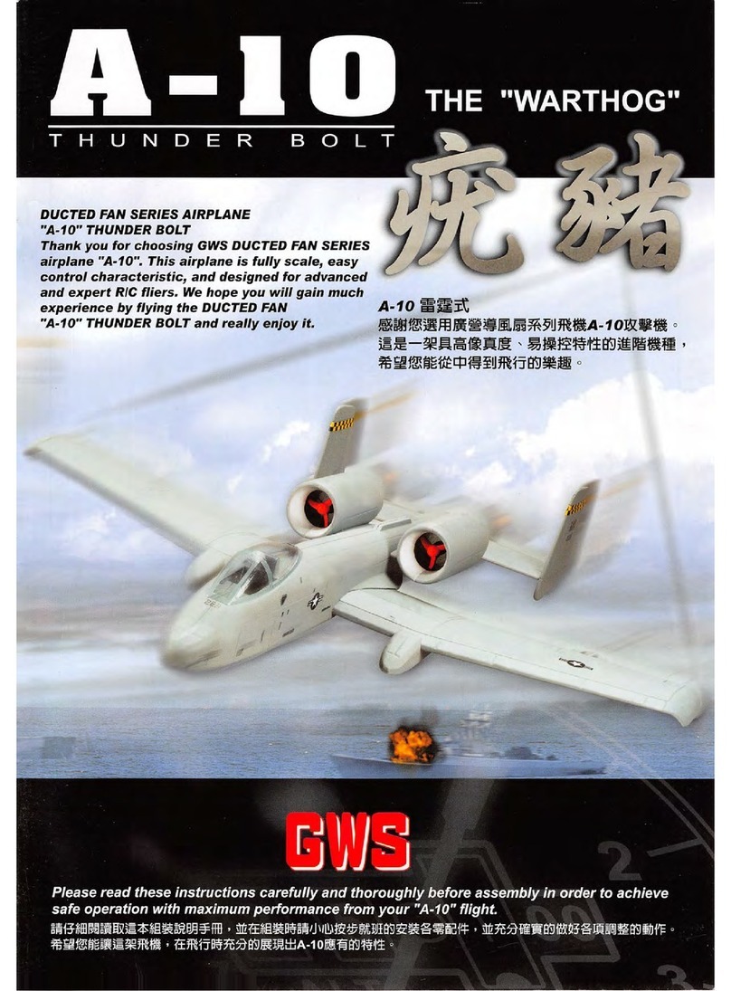
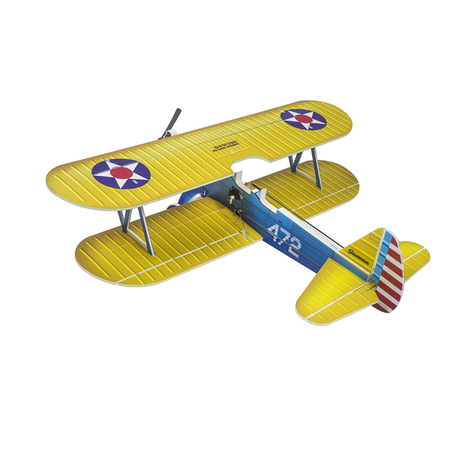
GWS E-Starter User manual

ane.
This
aiti
oe
a
beginne
Please
read
these
instructions
carefully
and
thoroughly
before
assembly
in
order
to
achieve
safe
operation
with
maximum
performance
from
your"E-STARTER"fiight

mC
ELECTRIC
AIRCRAFT
RADIO
CONTROL
SYSTEM
4
Channel
Transmitter
Overnight
Charger
Series
Servos
GWS
2-3
PICO
/
NARC
I
Electronic
Speed
Controller
ICS-300-480above
USER'S
GUIDE
—GBHQI
GW
E-STARTER
EPS-100C
Len91^ 72$mm(30,54in.)
Wing
Span.960irim37.BOin
V/ing Araa
I7.ldm
{26Sin}
Wing Loading 21 6 g fl)
flying Waignt 370 g(l3 02}
Pow«t Systom £P8>100C
PropellorEPlOID
Batltry
required
2/3AA
270-400mAh
/
7.2V
or
8.4V
Raaio
r6auired:3*
4
cftannei
radic
Servo
requirod:3xPICO.NARO.Mi^^l
Electronic
Speed
Controiter ICS'100
or
ICS-400
Receiver.R4N
orRSN
orrBM
GW
E-STARTER
EPS-300C
Length.7 mmj30.541nj
Wing Span
960fnm37.80in.
I7,tdm'i265in)
:ing:23g
/dm^7
6
oz/s^fl)
Flying Wetghl:39S 9(13 oz}
Power
Syalem:EPS-300C
Prope Her EP*
1080
Baitery regvired:2^3AA
270-400mAh
;7.2V
or
6.4V
Radio required.3- 4channel radio
Servo requ)red.3xP(C0.NAR0.MINI
Elecironic
Speed
Controfler.lCS>lQO
orlCS-400
Recelver:R4N
crRBN
orrBM
Wing Area
Wing
Length:725mrTt{3l
"Wing
SpaA:960mil
Wmg Area 17.tcIiT:s265;n'
Wing Loading 28 g ' dm((9 OZ/sgIt)
FlyingWeighUBO9(16 9 C2)
Power Syetem.EDP-400C
Prope(lerEP-703S
Beltery
raquirad:2/3AA
27C-40OmAh
i
7.2V
or
8.4V
Radio
required.3>
4
channel
radio
Servo
requiro
3aP
ICQ.NARO.MINI
Elec(ror>ic
Speed
Controlier.lCS>100
or
lCS-400
Receiver.R4Nor
R6N
or r8M
Quick Charger
7.2~9.6V
"AAA"
730mAh
(NI-MH)
7.2-8.4V
2/3
270-400mAh
or
7.2-8.4V
600mAh
(Ni-Cd)
FM
Receiver
GWS
R4PII or R6NII
TOOLS
AND
ITEMS
To
assemble
this airplane you
need
to
prepare
some
tools.
r7-!=i-r^rrnntr
m)
Cutter
Knife
Scissors
P
hers
Screwdriver
Nippers
Drill
Paper
Tape
OA
Glue

R/C
ELECTRIC
AIRCRAFT
GW/ESTARTER-FAS1
GW/ESTARTER-FAS5
njs-1010-w-L-
E-STARTER Fuselage(Left
Side)
PHFUS-1010-W-R-
E-STARTER
Fuselage(Right
Side)
PMSPC-1023
Push
rod lock
head
x
6pcs.
PTMEW-1035
Push
Rod ^I.Omm x 3pes. • m PTGUM-1014—
Rubber
Grommet
x
2pc5.
PTMEW-IOIS—A-
j .
PTMEW-1015—B-
AlleronLinkageWirei51.4mm(A)x1pce,(B) x
Ipce
PTSTK-1002—
Bamboo
Stick
Jsj3x240mm x
Ipce.
PTMEW-1015—U-
i
QgvAlor LInknge Wlre«1.4rivit x 1pc«.
PTPLX-1001-—
PtasUc
Tuttebz
5>2SmiT(i>leck)
<
2pcs.
PQTUBH035 T
Plastic
Pushrod
tube(Transparent)
35ix
460mm
Ipce.
PHWIN-1011
H-
E-STARTER
Horizontal
Tail
GW/ESTARTER-FAS2
PHWIN-1011
V-
E-STARTER
Vertical
Fin
3W/ESTARTER-FAS3
(LANDING
GEAR
parts)
PHWIN-1011—
E-STARTER Main Wing
PTMEW-IOIT—M-
Main Lanrfen
Gear
82.0mm x 1 p
PMSPC-1013—.
^ain
V^uig
Reinforcemen
PMTYRPlOOa—02-
L'ltM.iijiit WitfwjlR;m 50 RmmOja (2*Jx 2 [•:
.i
• ,
PTMEWAIOIO
^T-
'
41
ZmtnTaaDagparXf pea.
PHTYRP1005—01-
UFIra-iighi
Wheel Rim2S
4iTiflt
Cia.(10 x 1 pea.
PYCRD-1001~
Hinge(10x18mm)
(15
pcs)
PTSHE-1002—
Bamboo
Stick
Reinforcement
PTSTK-1003
PMfiTTl
inn7_
Saniboo
Sli««3x12Smmx2
pee.
1
pee.
EPS-400C
{ACCESSORIES
A)
^W/ESTARERT-FAS400C
PTPROA1060
Propellet
|EP1060)
x 1 pee.
Pevw
^
PMCHSA1005-—
EPS
Mount
lOilOiftOmin
SPtRIOll
poo
EDP-400C
(ACCESSORIES
A)
JW/SPITFIRE-FAS4d0""''^
f^CHSAIOOd
Propeller
{EP7035)
x1
pee.
>—Spinner
eSTOl-in02
M2o
Hoi
wrsndm
r>0(i
EPS-350C
(ACCESSORIES A)
GW/DHC2-FAS350
PTPROA1080
Propeller
(EP1060) x 1
pee.
CW;E^-350C
Elvctnc
Pmrer
SvMm
PMCH5A100S—
EPS
Mour(
10«l0ir90iTim
XI CM.
PYINS-1058
E-STARTER InstructionManual x 1 pee.
PTSTK-KXn
Baml>ooStiai^3x240(nnix3pee,
GW/ZER0-FAS6
GW/P-STICK-FAS6
(ACCESSORIES)
PiCO-ZERO
MICRO
ACCESSORIES
C
© ©
eg)
Sffi-nSrrns.
8SRB0.1001
PTCUS-TOifc—
GWSGkie 11 pcd. Rubbor Band x12pcs. T«Pi«4pe»
»ras(v>PL.i'iriii
^
Vr«T¥imrn^
L__fein_
AASMEDP400 PMCHSA1005
PVPEF-1040—1-
Cowling x 1
pee.
CONTENTS
OF
01. E-STARTER Fuselage(L) x1
02. E-STARTER
Fuselage(R)
x1
03.
E-STARTER Main Wing x1
04.
E-STARTER
Horizontal
Tail
x1
05.
E-STARTER
Vertical
Fin
x1
06.
E-STARTER
Bamboo
-
Stick
Reinforcement
x1
07.
Hinge
x1
08. Ultra-light
Wheel
Rlm(1") x1
09. Ultra-light Wheel Rlm{3") x2
10. Main Wing Reinforcement x1
11.
Battery
Seat
x1
12. Tall
Dragger
x1
KIT(PARTS
LIST)
13. Main Landing
Gear
x1
14.
Bamboo
Stick{^ 3x240) x3
15.
Bamboo
Stick(^
3x125)
x2
16.
Plastic
Parts
Frama'A"
x1
17.
GWS
Glue
x1
18.
Rubber
Band
x12
19. Double -
Sided
Foam
Tape
x4
20. Electric
Power
System
x1
21. Plastic
Pushrod
tube(Transparent)x1
22. Plastic Tub0(Black) x2
23.
Rubber
Grommet
x1
24. Aileron Linkage Wire
1?
1.4mm(A) x1
25. Aileron Linkage Wire 1.4mm(B) x1
PMSPC-I002
covrfing S«al x I pcs
26. Elevator Linkage Wire
1.4mm
x1
27.
Push
Rod
0.9mm
x3
28.
Plastic
Parts
Frame"C"
x1
29. Cowling Fixing
Screw
(Ml .4) x9
30.
Bolt
MSxSOmm
x1
31.
Washer
x1
32.
Cowling
Seats
x4
33.
Rubber
Grommet
x1
34.
Cowling x1
35.
Nut
x1
36.
E-STARTER
Decal
x1
37.
GWS
Deeal
38.Instruction
Manual
39.Push
rod
lock
head
2
PYPOP-1030—-C-
E-STARTER Decal x 1 pee.
PYPOP-1030—0-
E-STARTER
Decal
x 1
Dce.
PYPOP-1003
GWS
Decal
x 1
pee
w>n>.nirs.c<iin.ni
gWS.COnLtW
•rm.gwvcsiiiM

£^s7:4/fr£/f
RJC
ELECTRIC
AIRCRAFT
Step2
Apply epoxy glue to the
slot of fuselage,then put
the C (6) in place.
FUSELAGE
ASSEMBLY
Press
the
3mm
hexagonal
nut
into
the
plastic
c
(6) and apply a small amount of CA glue to the
c{6).
Frame"C"
Step1
230mm 230mm
460mm
PlasticPush RodTube(Transparent)
3^x
460 mm
A Cut the plastic tube to specific length
as
shown in the picture (230mm x 2).
Glue the tube in place with
GWS glue. Insert the plastic pushtod tube (230mm)
into the hole,from inside of the fuselage
and
come
out for approximately 10mm.
Drill
3mm holes into the L& Rfuselage
pushrod guide slot.
For bigger servo, please cut
the red portion on fuselage.
i
^i ^
[r.avoSDmAh {
Bra
•
For bigger batteries,
please
cut the red portion.
/S glue at the indicated area.
Tastercure time, you may use a 6-
'minute epoxy instead ofthe included glue.
I
Step3
Once glued, fixin places in 5 or 6 position using either a very low
tach masking tape and secure with tape that
does
not come in contact
with the painted foam.
WING
ASSEMBLY
Step4
! • Prepare
wing
accesories
£L
[^L_dl_,
R/C
ELECTRtC
AIRCRAFT
'Cut
the
aileron apart from
the
main wing
(both right & left) with a knift
as
per
the
groove.
%L
IF
Frame"C"
(1)Aileron linkage wire
(L&R)
(2)Black
rubber
tube
(X2
pcs)
Note: When you
are
cutting
out
the
aileron
some
of
the
bevel on the hinge line
needs
to be
cleaned
with a
sanding
block.
/
y
steps
•
Cut
the
black
rubber
tube
in
Push
the
rubber
grommet
into a coil of
the
aileron
linkage
wire. '
Slide
two
of
the
rubber
tube
onto
the
aileron
linkage
wire.
steps
Glue
the
bamboo
stick
for wing
enforcement
on
the
bottom
of
the
wing, (leading
edge)
•Put
the
aileron
linkage
wire into
the
aileron slot
and
glue
the
rubber
tube
in
places
and
trim
the
aileron
wire
as
showm.
Note:
The
channel
for aileron
torque
rod
needs
to
be
cut
deep
so
torque
rod is on aileron
hinge
line.

^^73//r/Zyr_
WING
ASSEMBLY
R/C
ELECTRIC
AIRCRAFT
Step
7
Mark
out
the
hinge (3
each
side)
and
linkage
wire
iocation.
Make
a
sign
on
the
main wing, aiieron
and
linkage wire
Drill
1.5
mm
dia.
&
10mm
deep
hole
on
the
aileron
and
cut
a
slot
to
accommodate
the
wire.
Cut
a
23.5
cm
bamboo
stick.
Insert
the
strut
fixing
base
A-7 to
the
polystyrene
foam
sheet
and
glue
them
to
the
designated
positions
located
on
both
side
of
the
fuselage
as
shown.
1. Cut a slit (10mm x 10mm) at 3
places
for
hinge installation on
the
main wing
and
aileron.
2. Apply
glue
on all
hinges
and
aileron
wire
then
insert
them
to
the
wings
securely.
Step8
fOW5
Frame"A"

WING
ASSEMBLY
£'-sr>!i/FrE/F
Step9
Frame"A"
Glue
the
plastic
part
C-5 on the
center
top of the wing with GWS glue. (Trailing
edge)
R/C
ELECTRIC
AIRCRAFT
{1)Siide two bamboo sticks into piastic frame"A(6)".
(2)Then
glue
the
polystyrene
foam
to
the
bamboo
sticks.
Glue
the
piastic
part
C-1 on
the
center
top of
the
wing with
epoxy
(Trailing
edge).
Drill
a^s^3mm
hole on the plastic part C.
StepW
Frame"C"
Glue the plastic part C-1 with epoxy
on
the
fuselage.
Apply
epoxy
glue
to
bond
the
part
C-2.
Put
the
part
0-2
in
the
indicated
place.
part
plastic
Trial fit the wing onto
the
fuselage
and
secure
by^3x30 screw. Linkthe struts to the strut fixing
bases
on the L&R
wings
&
fuselage.

£^S771l/fr£^-
R/C
ELECTRIC
AIRCRAFT
TAIL
ASSEMBLY
Step11
Cut
the
elevators
apart
from
the
horizontal
stabilizer
with a knife
as
per
the
groove.
'
Glue
the
horizontal
stabilizer
to
the
fuselage
with
epoxy
glue.
'
Glue
the
vertical
fin
to
the
horizontal
stabilizer
with
epoxy
glue.
'
Ensure
that
the
horizontal
stabilizer
is
perpen
dicular
to
the
fuselage
and
vertical fin.(Pic. 4
90°
rt—
6
Step13
Frame"C"
'
For
the
tail
gear
wire,
cut
a 1
mm
x 1
mm
x
20
mm
slit
and
drill
1mm
dia
&
25mm
deep
hole
on
the
rudder.
•Apply
GWS
glue
on
all
hinges
and
insert
elevator
llinkage wire
to
vertical
fin
and
rudder.
'Glue
the
frame"C-10"
to
the
tail
fuselage
with
epoxy
glue.
4
A=A
—
• Install
the
tail
gear
to
the
tail
fuselage
and
mark
on
the
rudder.
Step12
Cut
a slit
(10mm
x 10
mm)
at 3
places
for
hinge Installation on
the
horizontal
stabilizer
and
aileron
Cut
a slit
at
2
places
for
the
elevator
and
Insert
the
elevator
linkage
wire with
GWS
glue.
Apply
GWS
glue
on
all
hinges
and
elevator
llinkage
wire
insert
them
to
the
•fiorizontal
stabilizer
and
elevator.

MAIN
LANDING
GRAR
/
SPINNER/EPS
ASSEMBLY
r
Dn
ate by handdrill
as
picture
shown.
(Pic. 3)
£^S77l/fr£/f
R/C
ELECTRIC
AIRCRAFT
Step14
1.Apply
GWS
glue
to
the
cowling
mount
and
bonding on
the
nose
of
the
fuselage.
2.lnsert
the
EPS
mount
to
the
electric
power
system
(EPS).
Make
sure
that
the
mount
is
pushed
into
the
EPS
by
20mm,
if it is
too
tight to
insert
the
mount,
trim
the
mount
slightly with knife
or
sand
paper.
Put
the
power
system
in
the
fuselage
upper
chamfer,
making
sure
it fits
and
is not too tight,
then
puii it
out
(Pic. 4) Adjust to EDP-
400C
power
system
'Cut
out
the
extra
material
of
the
cowling.
IApply epoxy glue to
the
frame "0-14"
and
secure
the
landing
gear
to
the
mount
by
screws.
'
Cut
out
the
excess
material
of
the
battery
holder.
Insert
the
battery
holder
with
epoxy
glue
to
the
indicated
place.
'
Put
the
cowling in position
and
drill 1mm
dia. holes,
then
fix
the
cowling with 4
screws.
• • • @ ® ^
liZi
,
fV-
^
EL_
Drill a ^
1.4mm
hole
through
the
retainer.
Install
the
main
wheel
&tail
wheel
rims
on
the
main
landing
gear
& tail
wheel.

RADIO
CONTROL
SYSTEM
R/C
ELECTRIC
AIRCRAFT
Step16
•
Glue
the
horns
frame
"A-5"
on
the
elevator
&
rudder
with
epoxy
glue
•Put the
push
- pull rod through
the
guided plastic
tube
, for
rudder
please
use
left
side
tube
.
For
elevator
use
right
side
tube
, fix
the
control
horn
to
rudder
and
elevator
push
- pull rod.
StepU
rm£r
Frame"A"
•
Apply
the double side foam tape to the servos and stick
on the fuselage as picture.
• Usea
marking
pen markoutthe connecting
point
on the
push-pull
rod.
NoteiYou
will
need to
turn
on the power
while
servos assemblingto makesure
neutral position and directions.
• Bend a
"Z"
connector on marked pointof push-pull rodand cut the excess wire.
Step18.
For
bigger
servos
You may apply GWS glue to
servos
and
insert
the
servo
to
servo
slot.
•
PICO&NARO
Servos:
1
.Cut
out
the
extra
reinforcement
to
a
suitable
lamination
as
picture. (Pic. 2)
2.Cut the
excess
swell of servo slot away
as
picture.(Pic. 3
3.Glue
the
servo
&lamination to
the
main wing with
GWS
glue
as
picture.
4.Connectthe
push-pull rod
to
the
main wing.
CAUTION
The
horn
has
2
holes
if
you
use
inner
holelp^^
moving
angle
are
biggt
then
If
you
use
outer
A
CAUTION
The horn
has
3
holes
ifyou
use
Inner
hole
(£»ooo)the
moving
angle
are
bigger
then Ifyou use outer
holeO^^

7
-350CSYSTEWI
7
Black
Wire(-)
Electronic
Speed
Controller
ICS-300
Extension
Wire
CAUTION:
Please
read
the
instruction
careful
before
Installation.
Please
follow
the
scheme
showing
wiring
diagram
to
connect
the
wire
and
be
sure
the
servo
are
in
neutral
position.
When
you
are
testing
the
servo,
please
do not
connect
the
motor
wire
and
be
sure
to
turn
on
the
transmitter
first.
GWS
Ni-Cd
Battery
6N7.2V350mAh~600mAh(Ni-Cd)
7N8.4V~500mAh-730mAh(Ni-MH)
Aileron(GWS
PICO/NARO/MINl)
ELEVATOR(GWS
PICO/NARO)
EDP-400cSYSTEM
Receiver
GW/R-4P
GW/R-6NII
GW/R-8M
Electronic
Speed
Controller
ICS-480
4
RUDDER
(GW
PICO/NARO)
Red Wire(+)
=0=1'
BlackWire(~)
ir.'j
/.X
Receiver
Red Wire
GW/R-4M
BlackWire{")
GW/R-6M
GW/R-8M
Extension
Wire
QS
6N7.2V600mAh(Ni-Cd)
7N8.4V730mAh((Ni-MH)
GWS
Ni-Cd
Battery
Note: We
highly
recommend
GWS
8.4
V
730
mAh
NI-MH
batteries
over
and
above
when
you
use
servos
the
weight
over
NARO's.
Aileron(GWS
PICO/NARO/MINI)
ELEVATOR(GWS
PICO/NARO)
B ^
RUDDER
(GW
PICO/NARO)
O
5
o
o
z
H
7)
O
r
(/}
H
m
m J '
I

f-sm/rrfx
R/C
ELECTRIC
AIRCRAFT
BEFORE
FLYING
Please Note: Below photos show stick position using a Mode 1 transmitter. Mode 2
transmitters
used
in
the
U
.S.
market
will
have
throttle control
on
the
left
and
aileron/elevator
control on
the
right.
Turn
on
your
transmitter.
Stick
move
to left,
the
left
side
aileron on
the
airplane
will
move
up, and right side aileron move
down.
Stick
location
on
the
transmitter
varies
by
mode.
Aileron stick
move
to right.
The
right
side
aileron on the airplane
will
move
up .
and
left aileron
move
down.
Moving
the
stick up
should
move
the
elevator
|Y.2V/3ebmAh
Gws
K
Place
the battery in to
the
battery
compartment
of
fuselage.
I
I
Push
up the throttle stick slowly
and
watch
the
reaction
of
the
motor.
The
motor
should
run
from
low
to
full
throttle
as
you
adjust
the
stick
upward.
Stick In
neutral
position. All aileron
on
the
airplane
should
return
to
neutral.
If
the
movement
of aileron
are
working
in
opposite
direction,
please
switching
the
aileron
reverse
switch
on
the
transmitter.
GVJSiS
Moving
the
stick
down
should
move
the
elevator
up.
I
Connect
po^iimifes
and
turn on
the
receiv
Pull
down
the
throttle
to
the
lowest
position
and
also
the micro
adjustment
to the
minimum.
The motor should in
neutral position
and
no operation.
Moving
the
stick to
the
left
should
move
the
rudder
to
the
left.
Moving
the
stick to
the
right should
move
the
rudder
to
the
right.
(MOVEMENT OF ALLMOVING SURFACE)
1/2"up
^5/16"up
1/2"rlght
When the stickis inneutral, the /- \Piov/aw
elevator should return to neutral. ^
;cievator
1/2"down
11
(2)Alleron
5/16"down
,/1/2"left
(3)Rudder

For
the
correct
placement
of
decals
,
please
refer to
the
scheme
shown.
DECALS
®
1
E-ffmiiTEit
E-yrAItTER
liSmHTER
®
£'-sn^r£x
R/C
ELECTRIC
AIRCRAFT
<
Note:You
will
need
to
cut
the
decals
on
the
vertical
fin
and
horizontal
stabilizer
apart
with a knife
as
per
the picture
shows.
E-STABTER
www.gws.Gom.
www.gws.com.tw
.gWS.COm.tW
!www.gws.com.tw
12

PREFLIGHT
CHECKING
LIST
R/C
ELECTRIC
AIRCRAFT"
The C.G. is very critical and
It
Is important that you check and confirm the location for yourself before
flying.
Battery and other
changes
such
as
motors affect this positon
and
may require the
need
for stick
on lead weight to be added to the nose or the rear of the fuselage depending on whether the airplane
is nose or
tail
heavy. Using the EPS300C motor may require approximately 3/4 oz of lead weight added
to
nose
to
assure
the
plane
has
positive pitch stability.
EDP-400C
1.
Electric
power
system
(EPS-300C.EPS-100C.EPS-400C&EDP-400C)
2.
Batteries
3.
Extention
wire
&
aileron
servo
4.
Speed
controller
5.
Receiver,
rudder
servo
and
elevator
servo
6.
The
Center
of
Gravity
(C.G.)
7.
Float
stick
preparatory
portion
h
EPS
POWER
SYSTEM
SPECIFICATONS
Note: When you use 7.2 V 8.4 Vbattery please use
GWS
EP1080propeller and please use EP9070for 9.6 Vbattery.
GW/EPS-1
DOG-AS
Propeller Volts(v) Ampere(A)
Thrust
Power
Efficiency
(g) (oz) (g/w) (oz/w)
EP-1080
7.2
2.7
164
5.79
19,44
8.44
0.30
8.4
3.4
200
7.06
28.56
7.00
0.25
GW/EPS-300C-CS
Propeller \/olts(v) Ampere{A)
Thrust
Power
Efficiency
(g) (oz) (g/w) (oz/w)
EP-1080
7.2
7.8
288
10.16
56.16
5.13
0.18
8.4
9.7
332
11.1
81.48
4.07
0.14
GW/EPS-400C-CS
Propeller Volts(v) Amper8(A)
Thrust
Power
Efficiency
(g) (oz) (g/w) (oz/w)
EP-7035
7.2 7.8
288
10.16
56.16
5.13
0.18
8.4
9.7
332
11.1
81.48
4.07
0.14

PREFLIGHT
CHECKING
LIST
R/C
ELECTRIC
AIRCRAFT
1. It is
the
best
choice for you to fly your
plane
in
the
expanse
place.
2. Do not
fly
around
some
restricted location likeflight information region (FIR), military post, etc.
3. You
will
need
to
check
the
transmitter's
channel
around
you averting interfered. (Ifyou
are
flying with
other
RC
modeler
at a field, do not turn on your transmitter until you
are
certain
that
no
one
else
is
using
your
channel.)
4. Always turn on
the
receiver last after turning on
the
transmitter
and
shut
off
the
receiver first
before
turning off
the
transmitter.
5. Ifyou
are
only a beginner for
the
radio control model flying, do not attempt to flyyour model
without
any
assistance
or
advice
from
advanced
and
expert
fliers.
6.
Please
refer to the instruction guide carefully
and
thoroughly before
assembly
equipment kits.
Different
power
units
and
servos
combination
will
lead to its various flight performance.
7. Be
sure
to
check
the
wind direction
before
landing
or
taking off.
V /
TAKE
OFF
1. Take off
and
speed
up
the
airplane Into
the
breeze
and
let
the
tail rising for
the
run-up.
2.
Keep
up
the
tracking straight during
the
run-up
process.
3. Apply
just
a
touch
of
up-elevator
when
the
model
reaches
sufficient takeoff
speed
and
the
model liftssmoothly into
the
air.
4. Make
the
turn
when
the
model is
at
a high altitude.
Then
trim all
control
surfaces
to
achieve
the
level flight.
LANDING
r r
lillThe
Wind
Direction
III
I
The
Wind
Direction
1. Maintain
at
a
safe
altitude
against
the
wind.
2. Gradually
reduce
the
throttle during
the
landing
pattern
for a
smooth
touch down. (Landing
requires
at
least
about
1/3 throttle)
3. Pull
the
throttle
backward
and
slightly touch up-elevator
when
the
decent
approximately 30 cm from
the
ground. After
the
main landing
gear
genteelly
landing
to a
runway
then
reduce
the
speed
until
the
tail
wheel
contacts
to
the
ground.
Table of contents
Other GWS Toy manuals