GWS Spitfire User manual

luc/i
uw^ci
mi
so
mam
ra
jcj
m.
/
Thank
you
f<w^oosing
GWS
WWII
Fighter
sen
designed
for
advanHced
and
expert
R/C
fliers
and
outside
loop,
Cuban
8,
inverted
fiight,
staii
turn
e
.
^'%.50P3iS:5i.
^5^is:^ ^
as
^mm - wiTi^
DW3
During
WWII)
by-Wit'Man
(JJiiAi'c'nlll
cmjt
11
Please
read
these
instructions
carefully
and
thoroughly
before
assembly
in
order
to
achieve
safe
operation
with
maximum
performance
from
your
"SPITFIRE"
flight
•M

RIC
ELECTRIC
AIRCRAFT
mm
mm
USER'S
GUIDE
mmm
Length
Wing
Span
Wing
Area
Flying Weight
Wing Loading
Power
System
Propeiler
(H
Length
Wing
Span
Wing Area
Flying Weight
Wing Loading
PowerSystem (i!);t)r^lS)
Propelier
(llJIig)
(±m)
Length
Wing
Span
Wing
Area
Fiying Weight
Wing Loading
I)
(^S)
mm)
I)
I)
(mmm)
SPECIFICATIONS
S
ii
7C
SPITFIRE
EPS-300C
720mm
(28.4 in.)
876mm
(34.5 in.)
13.8dm^
(213.9
sq.in)
390g
(14-15
oz)
28.3g/dm2
(9.5
oz/sq.ft)
GW/EPS-300C-CS
EP-1080
BatteryRequired
(®1fi^Mf§):
6N7.2V~7N8.4V
400~600mAh
(Ni-cd
Sil)
7N8.4V~8N9.6V
730mAh
(Ni-MH
lifi)
Servo Required ((IflSI^) : PICOor
NARO
Series
(1^50)
Electronic Speed Controiier
(®^®5l^):
ICS-100
Receiver (JglK®) :
R4N
/
R6N
/
R8M
Radio
Required
(JSlKI^)
:4 Channei
Radio
(IM'P)
SPITFIRE
EDP-400C
720mm
(28.4 in.)
876mm
(34.5 in.)
13.8dm2(213.9
sq.in)
450g
(15-17
oz)
32.6g/dm2
(10.7
oz/sq.ft)
GW/EDP-400C
EP-7035
BatteryRequired
(®)t!3^Mt§):
7N8.4V
400mAh-1000mAh
(Ni-cd
gll)
7N8.4V-8N9.6V
730mAh
(Ni-MH
ISfi)
Servo Required (i^iSI^) : PiCOor
NARO
Series
(IS^!))
Eiectronic Speed Controller
(®^®jli§):
ICS-400
Receiver (JglKH) ;
R4N
/
R6N
/
R8M
Radio
Required
(I^®®) :4
Channel
Radio
(BCP)
SPITFIRE
SLOPE
GLIDER
(M
^ ^ )
720mm
(28.4 in.)
876mm
(34.5 in.)
13.8dm2(213.9
sq.in)
230-330g
(8.11-11.6 oz)
16.7-23.9g/dm^
(5.8-9.95
oz/sq.ft)
- 1
BatteryRequired (B;t!3^1f§)
Servo Required ((^fllsll)
Receiver (JSlJS^)
Radio Required (Jglji/®)
4N
"AA"
600mAh
(Ni-cd
llil)
PICOor
NARO
Series
(1^50)
R4N
/
R6N
2-4
Channel Radio(Bj'F)

SPITFIRE
GW/SPITFIRE-FAS1
PHFUS-1009-W-R- Fuselage(R)
Meiy
x1pce
PYINS-1059
x1
pee.
Instruction
Manual
SPITFIRE
$
_
PHFUS-1009--W-C
Cockpit
y
x1pce
PYPOP-1028
SPITFIRE
Decalxipce
PHFUS-1009~W-L- Fuselage(L)
x1pce
?
-5y.-c
GW/SPITFIRE-FAS2
PHWIN-1012
Main Wing X1
pee.
••II
PHWIN-1012—H-
Horizontal
Stabilizer
xipee.
GW/SPITFIRE-FAS5
PVPEF-1037 PVPEF-1038—A-
Canopyl^lli^
(Bright
^ii)
x1
pee.
GW/SPITFIRE-FAS300
PTPROA1080
Propeller il]5^ii(EP1080)x1 pee.
AASMEPS
301
Electric
Power
System
myjm-a:
^
GW/EPS-300C-C
PHSPIR1012—--
40 Spinner 3^9|^Si3
PMCHSA1005
EPS Mount
SXlliixIpee.
PYCRD-1001
/SMin
x1
pee
PYPOP-10Q3
GWS
Decal
x1
pee
IfilE-
www.gws.com.tw
SnS
nraiwi
5WSDWS
w«rw.gws.coai.iw
WWW.gWS.COm.IWwww.gws.cam.tw
PVPEF-1039
PVPEF-1038
Cowling^5^^x1pee.
RabiatorjlSi^
(WhiteS)x2pes.
GW/SPITFIRE-FAS400
- 2
PMCHSA1005 Propeller 11
W(EP7035)x1
pee.
M0
'^UJj^SPIRIOlO
8STOL-1002
. '
40
Spinner
4^1
M2.6 Hex Wrench J
AA'S1\4EDP400
AASMEQP400-P—•
PHCAB-1081-—
xIPee.
PMCHSA1005-
EDP-400
Electric
Povvw
System
EPS
Mounf0x10x90mm
mumt
(white
wood
S:i^)x1pee.

SPITFIRE
GW/SPITFIRE-FAS3
PTMEWA1010—T-
Tail
Dragger
Hlilli
isj1.2mmx1pce.
PHTYRP
1005
-D1-
Ultra-Light
Wheel
Rim
25.4mm dia (1")x1pce.
PTMEW-1018
Main Landing
Gear
isj2.0mmx1pce.
PMSPC-1013
Main
Wing
Reinforcement
PHTYRP
1006
--D2A-
Ultra-Light
Wheel
Rim
50.8mm dia (2")x2pce.
GW/SPITFIRE-FAS4
PTMEWA1001 Push RodiiP^iis}0.9mm x3pcs.
PQTUBH035 T Plastic Pushrod Tube itlWMW
(Bright
^@§)x2pcs.
PTSTK-1002 Bamboo Stick ^3x240mm x Ipce.
PTMEW-1015—U-
)PTMEW-1015—A- PTMEW-1015—B- ,
If
- Elevator Linkage Wire
Aileron
Linkage
Wire
HySiliiOff
isjl
.4mm(L)x1
pce,(R) x 1pee
is)1.4mm X
1pce.
PTFLX-1001
PTGUI\/]-1014
•!
I • Plastic Tube MW * • Rubber Grommet
0P^
x2pcs.
^2.5x25mm (Blackil)x2pcs.
GW/SPITFIRE-FAS6
(SPITFIRE Accessories C)
(SPITFIRE
PMSPG-1008—1~
Plastic
Parts
Frame
"C"
MPiE#
0
xlset
, 1
a
PXISOF-6P-3030—
=?
Bolt
M3 X
30mm
x 1
pee.
PXTPAF-4J-1490R-
Cowling Fixing
Screw
X9
pcs.
PTWEG-1001
Clay
X
1pce.
GW/P-STICK-FAS6
(SPITFIRE
Accessories
A)
(SPITFIRE
^MA)
PMSPC-1001
Plastic
Parts
Frame
"A"
Ax
1
set
fGWS
PMSPC-lOQl]
^
8SADHP1003
GWS
Glue
SffliiZK
X1
pee.
8SRBD1001
Rubber
Band
x 8
pcs.
tiKSi58li^
PTCUS-1016
Double-sided
Sponge
Tape
X4
pcs.
'mmmmMM
PTSHE-1001
Plate iiiM'x 1pee.
PMS^^02
cowling
seat
(1x8x8) X
4pcs.
%L
jL
PWNUTF43183005-
PWWAHF63053208-
Nut
^ipi X
Ipce.
Washer
^^IS
x
Ipce.
M3
X
1.8mm
o
PTMAG-1001
^rcular
Magnet
X
Ipce.
- 3 -
PTGUM-1007
Rubber
Grommet
t^igWS(PiCO)
5 x3 mm x 1
pee.

RADIO
CONTROL
SYSTEM
^ ^
4
Channel
Transmitter
4
Bi'Ffgtifli
7N8.4V~8N9.6V
730mAh
(Ni-MH
US)
6N7.2V~7N8.4V
400(Ni-Cd
lllra)
SPITFIRE
ICS-100/ICS-400
Electronic
Speed
Controller
Charger
GWS
PICO,
NARO
Series
Servos
GWS
R4N
/
R6N
/
R8M
FM
Receiver
Servo
Extension
Wire
j
'^TOOLS
AND
ITEMS
^1
To
assemble
this
airplane
you
1
need
to
prepare
some
tools.
Cutter
Knife
mx73
-mi
-Tin
P
hers
Triangle
Screwdriver
A
Nippers
mam
Scissors
mD
Drill
Paper
Tape
Alcohol
mxmm^
;is
Clamp
Spray
Paint
CAGlue
ana
Epoxy
CONTENTS
OF
KIT(PARTS
LIST)
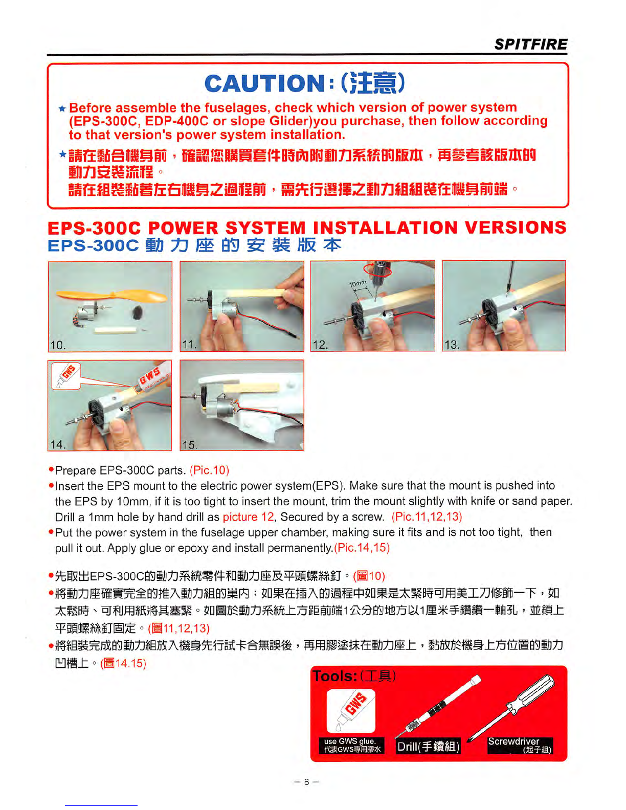
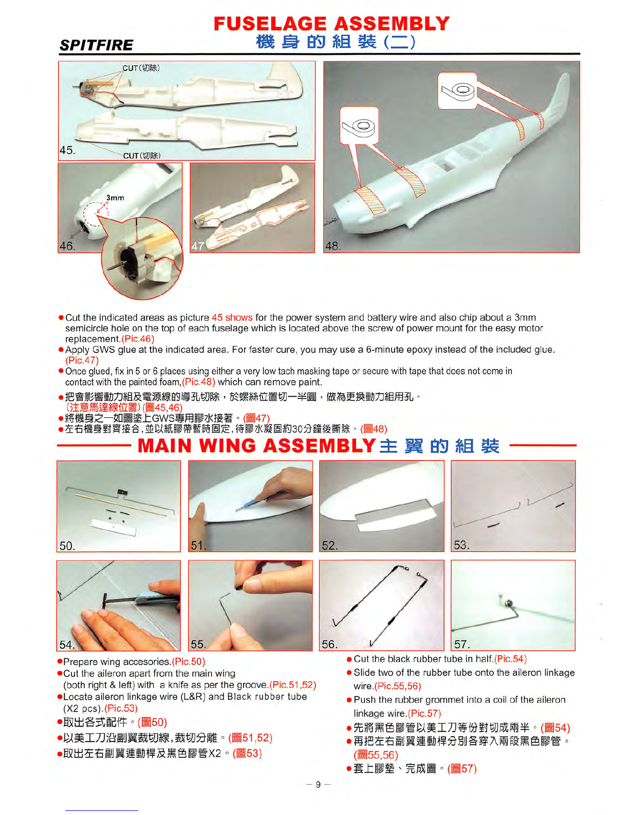
01. SPITFIRE Fuselage(Left Side) x1
02. SPITFIRE
Fuselage(Right
Side) x1
03. SPITFIRE Cockpit x1
04. SPITFIRE Main Wing x1
05.
SPITFIRE
Horizontal
Stabilizer
x1
06. SPITFIRE
Canopy
x1
07.
SPITFIRE
Cowling x1
08.
SPITFIRE
Radiator
x2
09.
SPITFIRE
Small
Radiator
x1
10. Main Wing Reinforcement x1
11. Ultra-light Wheel Rlm(2") x2
12. Ultra-light Wheel Rim(1") x1
13. Main Landing Gear((s(r2.0mm) x1
14. Tail Dragger(is)r1.2mm) x1
01.
SPITFIRE
Sf,!l1i#(L)
x1
02. SPITFIRE
eji1i#(R)
x1
03.
SPITFIRE
ffiiilS
x1
04.
SPITFIRE
x1
05. SPITFIRE 7j<q^)lH x1
06.
SPITFIRE
^11?
x1
07.
SPITFIRE
x1
08. SPITFIRE
mUW
x2
09.
SPITFIRE
x1
10.i«M®)=^
x1
11.ffi^3i'l'ili(2") x2
12.
ffi^?ltili(1")
x1
13. iliSi('s)r2.0mm)
x1
14. )ili?g(is(r1.2mm)
x1
15.
Push
Rod Tude(is(r3.0x460mm) x2
16.
Plastic
Tube
is)r2.5x25mm x2
17.
Rudder
Grommet
x2
18. Aileron Linkage Wlre(L) x1
19.
Aileron
Linkage
Wire(R)
x1
20. Elevator Linkage Wire x1
21.
Push
Rod((s)r0.9mm) x3
22.
Plastic
Parts
Frame"A"
x1
23.
Plastic
Parts
Frame"C"
x1
24. Bamboo Stick((s}r3x240mm) x1
25. Clay x1
26. Circular Magnet x1
27.
Plate
x1
28. Rudder Grommet(is!5x3mm) x1
— m m —
15. Et¥gg(is!r3.0x460mm) x2
16.
MfigS
(s)r2.5x25mm x2
M.wmmmnmm
x2
18. iyHjSii!)tf(L)
x1
19. HiJHjMli]tf(R)
x1
20.9TPSIEUS5ltf
Xl
21. jtJ3ltf(isir0.9mm) x3
22.
"A"
xl
23.
UBiiBft
"C" xl
24. (is;r3x240mm) xl
25.
xl
26.
BiyiliS
xl
27.
xl
28.
(<s)5x3mm)
xl
- 4 -
29.
30.
31.
32.
33.
34.
35.
36.
37.
38.
39.
40.
41.
Bolt(3x30mm) xl
Washer(3.2x8x0.5) xl
Nut(M3) xl
Cowling Fixing Screw(M1.4x9mm x9
Electric
Power
System(EPS-300C
or
EDP-400C)
or
Slope
Glider
Parts
Eps
Mount(10x10x90mm)
Propeller(EP1080 or EP7035)
Double-Side
Sponge
Tape
GWS
Glue
Rudder
Band
Instruction
Manual
Me-109
Decal
GWS
Decal
29.
30.
31.
32.
33.
34.
35.
36.
37.
38.
39.
40.
41.
mB
(3x30mm)
(3.2x8x0.5)
llfi
(M3)
MMMBSl
(M1.4x9mm
TPA)
K)T]!iti(EPS-300C or EDP-400C)
^ (10x10x90mm)
(EP1080
or
EP7035)
mm
GWS
I
mm
Me-109
Me-109
Ifiiffi
GWS
Ifilfi
xl
xl
xl
x4
xl
x8
xl
xl
xl
xl
xl
xl
x9
xl
xl
xl
x4
xl
x8
xl
xl
xl

FUSELAGE
ASSEMBLY
^
03
Si
(—)
SPITFIRE
Fuselage
parts
list
as
follows:
(1) SPITFIRE Fuselage L&R.(Pic. 1)
(2)Plastic pushrod
tube
(c|)3mm X
420mm).(Pic.
1-1)
(3) Plastic parts frame "C" NO.® (Pic.2)
(4) Plate 3mm Nut.(Pic.2-1)
°
(H.I)
^
(2) i4^^'f4^,®;^(})3mm x
L420mmMP#W(H.1-1)
(3)
cmmmi^
°(H.2)
(4)
3mm!lLl^i
°(H.2-1)
Plate
3mm
Nut.
(»ftili3mmtlli)
2-1.
Frame"C"(g-(4C)
1-1.
420mm
•J
310mm
3.
/
3lOmm
6
7
/.
/1
•
Cut
the
plastic tube to specific length
as
shown in
the
picture.(310mm x2) (Pic.3,3-1)
•
Drill
03mm
holes into
the
L
and
Rfuselage pushrod guide slot. (Pic.4)
• Insert the plastic pushrod tube (310mm into the hole, from inside of fuselage
and
come
out
for approximately 10mm. Glue
the
tube in
place
with
GWS
glue. (Pic.5)
•Press the hexagonal 3mm nut intothe plastic part 0®, and apply a small amount of CAglue to the
C®,
make sure
you
do
not
get
the
glue on
the
theads.
(Pic.6,7)
• Insert the
C®
into the slot of the fuselage
and
glue itsecurely. (Pic.8,9)
•Hf
03mm
XL420mm
x2^P®5DHin
'
®iij]^310mm
x 2 °
(H3,3-1)
>
si^Gwssffi§i7j(jg^iii:£iomm
°
(bs)
03mm3i«BAieffC©
> °
me,7)
•mmmAcmmmp^mhJommmyK
°
(ms.g)
- 5 -
use
CA
giue

SPITFIRE
CAUTION:
(H^)
★
Before
assemble
the
fuselages,
check
which
version
of
power
system
(EPS-300C, EDP-400C
or
slope
Glider)you
purchase,
then
follow
according
to
that
version's
power
system
installation.
in7]s8igtii
°
EPS-300C
POWER
SYSTEM
INSTALLATION
VERSIONS
EPS-300C
• .
-•ffSIK
•Prepare
EPS-300C
parts.
(Pic.10)
•Insert
the
EPS
mount
to
the
electric
power
system(EPS).
Make
sure
that
the
mount
is
pushed
into
the
EPS
by 10mm, if it is too tight to insert
the
mount, trim
the
mount slightly with knife or
sand
paper.
Drill
a 1mm hole by
hand
drill
as
picture 12,
Secured
by a screw. (Pic.11,12,13)
•Put
the
power
system
in
the
fuselage
upper
chamber,
making
sure
it fits
and
is
not
too
tight,
then
pull it out. Apply glue or epoxy
and
install permanently.(Pic.14,15)
•^i5i±iEPs-3ooca^il];til^^i?c^1^ffiiJ;t]JlS^5lllMIJ
°
(Hio)
°
(Hi
1,12,13)
°(H14.15)
✓
^ use
GWS
glue.
|Drill(¥M)
Screwdriver
- 6 -

SPITFIRE
EDP-400C
POWER
SYSTEM
INSTALLATION
VERSIONS
EDP-400C
20.
v
17.
•Prepare
your
EDP-40GC
parts.(Pic.16)
• Fix
the
adapter
to
the
motor
shaft
with
hex
wrench.(Pic.
17,18)
• Install
the
EDP-400C
motor
by front 2 bolt
and
use
rubber
band
to
keep
it in place.(Pic.
19,20,21)
•Insert
the
EPS
(GW/EMM-400
A)
mount to
the
motor
mount
and
secured
by a screw.(Pic.22,23)
•
Put
the
power
system
to
the
fuselage
lower
chamfer
making
sure
it is fit
and
not
too
tight (You
may
have
to
clean
some
styro
form
out
from
this
chamfer
as
shown
on pic.
24)
•
Put
the
power
system
in
the
fuselage
upper
chamfer,
making
sure
it fits
and
is
not
too
tight,
then
put
it
out.
•Apply
glue
or
epoxy
and
install
permanently.(Pic.25,26)
°
caie)
°
(hi/.ib)
•)ifEDP-4oo,iiii^tisisiii:^i£,i^ig^'
°
(>19,20,21)
•jDHJif
GW/EMM-400 A ° °
022,23)
.EDP-4ooc,iiifi!ii}iAttigWP§il'
o
(^24)
>
mmmmmmmmh
>
ifi]55(B$^#65isAiT75fiZB
J:
°
(B25,26)
ools:
i_LP
use
GWS
glue.
ttSGWSSfflB^K
- 7 -
✓
Screwdriver
I\/I2.6
Hex
Wrench

g,
@ O
'5
O
For
motor
location
,^11
I39.A^
&t
battery
connector
SLOPE
GLIDER
VERSIONS
SPITFIRE
42.„..
::i
•
Prepare
the
parts
for
slope
Glider
as
picture
27
and
battery
(Optional part)
as
picture
28.
•install
the
bushing
to
the
front
side
and
back
side
of
EPS
frame
as
picture
29,30,31,32,then
insert
the
shaft
as
picture
33,34
and
the
turn
it
other
side
and
put
the
washer
in it
and
secured
by a E-ring
(Pic.35,36,37).
•insert
the
EPS
mount
to
the
EPS
frame
(Pic.38) Before glue itto
the
indicated cavity,
please
refer
page
9 of
fuselage
assembly.
To
set
up
the
battery
pack,
first of all,
put
the
battery
connector
to
the
other
cavity.
(Pic.41,42)
•
Refer
page
15
for cowling
installation.(Pic.43,44)
•iiI5tli«f^®(5PB27)SS)tfi
(^li)
(5nB28) °
(H29,30,31,32,33,34,35,36,37) °
(B39,40)
°(B41,42)
°(B43,44)
CAUTION:
Please
note
that
the
Slope
Glider
does
not
include
the
propeller, motor,
gearbox,
main
landing
gear,
tail
dragger,
and
ultra-light
wheel
rim.
8 -

FUSELAGE
ASSEMBLY
g
eg
Si
^
(n)
SPITFIRE
^puTmm)
CUT
mm)
3mm
•
Cut
the
indicated
areas
as
picture
45
shows
for
the
power
system
and
battery
wire
and
also
chip
about
a
3mm
semicircle
hole on
the
top
of
each
fuselage
which is
located
above
the
screw
of
power
mount
for
the
easy
motor
replacement.(Plc.46)
•Apply
GWS
glue
at
the
indicated
area.
For
faster
cure,
you
may
use
a
6-mlnute
epoxy
instead
of
the
included glue.
(Pic.47)
• Once glued, fixIn5 or 6 places using either a very low tach masking tape or secure with tape that
does
not come in
contact with the painted foam,(Pic.48)
which
can
remove
paint.
(•45,46) °(H47)
MAIN
WING
ASSEMBLY^
M
S3
i
•
Prepare
wing
accesories.(Pic.50)
•
Cut
the
aileron
apart
from
the
main
wing
(both right & left) with a knife
as
per
the
groove.(Pic.51,52)
•
Locate
aileron linkage wire (L&R)
and
Black
rubber
tube
(X2
pcs).(Pic.53)
°(H50) °(•51,52)
•S5[UiSiiJH5lBt?Slg0i®X2
=(BSS)
- 9
•
Cut
the
black
rubber
tube
In half.(Pic.54)
•
Slide
two
of
the
rubber
tube
onto
the
aileron
linkage
wire.(Pic.55,56)
•
Push
the
rubber
grommet
into a coil of
the
aileron
linkage wire.(Plc.57) °
(B54)
(B55,56)
•Mxmm
- =(M57)

MAIN
WING
ASSEMBLY
mm
SPITFIRE
Decal
50mm
Decal
®)
80mm
80mm
,
65mm
10mm
Put
the
aileron
linkage
wire into
the
aileron
slot
and
glue
the
rubber
tube
in
places
and
trim
the
aileron wire
as
shown.(Pic.58,59)
Mark
out
the
hinge
(3
each
side)
and
linkage
wire location.
Make
a
mark
on
the
main wing,
aileron
and
linkage
wire .(Pic.60)
•For
the
aileron
linkage,
cut
a 1mm x 1mm x
50mm
slit.
Drill
1mm dia.
&10mm
deep
hole
on
the
aileron.(Pic.61,62)
•Cut
a slit
(10mm
x
10mm
)
at
3
places
for
hinge
installation on
the
aileron.Then
apply
GWS
glue
to a
half of
the
hinge
and
insert
them
into
the
aileron slits.(Pic.63,64)
•Apply
GWS
glue
on
all
hinges
and
aileron
wire
then
insert
them
to
the
wings
securely.
(Pic. 65,66,66-1)
•Glue
the
main
gear
mounts(plastic parts"c" NO.(D)on the bottom of the wing(leading
edge
side).(Pic.67)
•GWS
glue
the
bamboo
stick for wing
enforcement
on
the
bottom of
the
wing, (leading
edge)
(Pic.68,69)
•)lfiySJiI#]55AE]^ra
' ° (•58,59)
°(•60)
•5nH]5$iSSlJSl^iil^llI7]®—M50mm;^1mm[H]|i
° ' ]5$50mmjiZM^i±l/^1
OmmQ^
°(H61,62)
°(•63,64) -
Hf
o(H65.66,66-1)
•}|fiBf^C(D5n^l.i(SfflP7i(g]^ilill@S^i
°(H67)
•
Hf
03x24OTa^iMA[H]til^3]z^±GWSSfflP7X ' ° (B68,69)
Assemble
left
and
right
sides
the
same
way.
ii
=
-10-

MAIN
WING
ASSEMBLY
SPITFIRE
•
Glue
the
main
wing
reinforcement
on
the
center
top
of
the
wing (trailing
edge)
and
secure
with clips
for 5
minutes.(Pic.70,71)
• Glue the plastic part Cd) on the center top of the wing with CAglue.(Trailing edge).(Pic.72,73)
•
Drill
a 0
3mm
hole on
the
plastic part C.(Pic.74)
•Glue
the
plastic part
CCD
with epoxy on
the
fuselage.(Pic.75)
•
Drill
a 0 3mm hole through the plastic part
CCDon
the fuselage for connecting plastic part
(2)
.(Pic.76)
• Put the part
C®
in the indicated place.(Pic.77,78)
•Place the plastic part C@in the position and install the main wing and glue plastic part C @
as
per
guide
holes.(Pic.79,80,81)
°
(^70,71)
°
(>72,73)
'5Ll^iltM-l^03mm °(B74)
075)
°
(>76)
•
(>77,78)
luB
' ° (•79.80,81)
mmc®
ifiiijiu^EPiijsBf^
±0^
Tools:
(IM)
use
GWS
glue
-11-

jV...U10mm
10mm
TAIL
ASSEMBLY
$§
^
saaa
15mm^
30"!"^
<
-*
->
40mm
A
40mm
SPITFIRE
?Omm
Cut
the
elevators
apart
from
the
horizontal
stabilizer
with a knife
as
per
the
groove.(Pic.82,83)
Use
atriangle to
determine
the
center
of
the
horizontal
stabilizer
and
mark
indication lines
as
shown,(Pic.84)
but
wait
to
glue
until.(Pic.
87)
Ensure
that
the
horizontal stabilizer is
perpendicular
to
the
fuselage
and
vertical fin A=A'. (Pic.85)
Check
the
horizontal
stabilizer
with
the
wing
and
adjust
the
alignment
as
described.
(Pic.86)
Make
sure
all is in
place,
then
spread
the
glue
on
the
horizontal
stabilizer
which
contacts
the
fuselage.
(Pic.87)
Drill
1.5mm
dia.
deep
hole
on
the
aileron
and
cut
a
slot
to
accommodate
the
wire.(Pic.88,89)
Cut
a slit
at
2
places
for
the
elevator
and
insert
the
elevator
linkage wire
securing
with
GWS
glue.
(Pic.90,91,92)
Cut
a slit
(10mm
x
10mm)
at
4
places
for
hinge
installation
on
the
horizontal
stabilizer
and
aileron.
(Pic.93,94,95)
Appy
gws
glue
on
all
hinges
and
elevator
llinkage wire
and
insert
them
into
the
horizontal
stabilizer
securely.(Pic.96)
°(•82,83) °
(184)
°(•85) °(•86)
°
(^87)
]5$Uiyiit?fiZMi!IJllB5i^01.5mm5L °
(^88,89)
'
M5i^u§yMtf^-tGwsii7mA5nB
°(•90,91,92)
'
I^BtSHBi^illBtJ.^^IOxlOmmtjn
°(•93,94,95)
°
(^96)
-12-

SPITFIRE
•
K-
50mm
•>K-
70mm
96.
—-
\ ©
99.
100.
25mm
•Cut two slits for
hinges
installation on
the
rudder. Insert
the
two hinge
and
glue
them
in place.(Pic.96)
•For tail
dragger
installation,
cut
a 1mm
deep
and
16mm
long slit.(Pic.97)
•
Drill
a
01mm
&
25mm
deep
hole on
the
rudder
as
shown.(Pic.98)
•
Tail
steering assembly, insert
the
tail
gear
into
the
bracket (plastic parts
C®)
then install
the
Ultra-lightwheel (25mm dia.) and
fix
itwith the retainer (plastic parts A®).(Pic.99,100)
•
Glue
the
steering
set
to
the
rudder
securely.(Pic.101,102)
•Glue
the
hinges
and
install
the
rudder
to
the
vertical fin.(Pic.103)
• Glue the
C®
to the fuselage.(Pic.104)
• "
(BOB)
• '
RiBmm
^
)^Mlmm
°(H97)
•
IHil
mmiltl
^25mm;^0^11lfiil^^iS5L ° (H98)
•
^f^iii:25mmiifsiiii
-(•99,100)
• °
(Bioi,io2)
• °
(Bios)
mm
°(B104)
use
GWS
glue.
use
Epoxy
glue.
-13-

MAIN
LANDING
GEAR
ASSEMBLY
SPITFIRE
•
Locate
main landing
gear
system
including. Main
landing
gear(
2.0mm
piano wire), ultra-light
wheel
rimx2,
Screwsx2,
Retainers.
(GWS-STICK-FAS6#1x2) (Pic.105)
•
Secure
the
landing
gear
to
the
mount
with
screws,
as
picture
shows.
•
Fix
the
retainer
to
the
axle.
(Rio.
108,109)
''
• A
complete
landing
gear
installation. (Pic.110)
•
2.0mm3Eli§15
'
llMlix2
'
^5l3ilfJJx2
°
(GWS-STICK-FAS6#1)x2 °
(Hi05)
•m
2.0mm^li§15MAi^liSl]gi:Stia]zll±^5l!imiJlll^ili^
°
(Hioe.ioz)
• °
(Bios.
109)
°
(B110)
COCKPIT
ASSEMBLY
M M
QD
^
it
•
Press
the
magnet
into
the
plastic part C®. (Pic.111)
•Apply
a small amount of OAglue to the
0®.
(Pic.112)
Frame
"A"
^#"A"
•
Use
epoxy
Glue for plastic
part
C®to
the
recess
of
the
cockpit. (Pic.113,114)
•
Secure
aslice of metal with
epoxy
glue
.(Pic. 115)
•Glue
the
plastic part
C®on
the
recess
of
the
fuselage. (Pic.116)
•
Drill
two 3mm holes on the fuselage of the plastic part C®for connecting part C@of canopy. (Pic.117)
°
(Bill)
• °
(^112)
•
»m^®l^ABP5nBlll^]5$J^lli[a]:®tiiiZB
°(B113,114)
• °
(Bii5)
°
(Biie.)
•B$IBfi^C®Ji5LfiZM1^3mm#lili-|ffl5L
®B117)
-14-

SPITFIRE
"""^SssS
119.
• Set the plastic part
C(2)
to plastic part
C®
as picture
118,
then place the
cockpit to
fuselage
(Pic.119) to
get
the
imprint on
the
cockpit for plastic part
C(2)
installation and glue the plastic part
C(2)
to the position ofthe
imprint.
(Pic.121,122)
M7lfC@|fi[i]Jlii^ilJ^E|]SyHS5i05fiZM_t °(HUB,119,120,121,122)
COWLING
ASSEMBLY
S ^
BD
$1
li
•
Prepare
wing
accessories.(Pic.123)
•Glue 4
pieces
of
the
cowling
seat
to
the
fuselage
at
the
indicated
areas.(Pic.124)
•According to
the
cutting guideline,
cut
cowling
1,2,3,4
and
drill
holes
of
1.0mm
dia
hole
on
the
cowling 1
mount
(4
places)
and
fix
the
cowling 1 with 4
pieces
of
1.47
x 9
mm
screw.
(Pic.125,126,127,128,129)
•
Glue
the
cowling 2, 3, 4 in
place
with
GWS
glue.(Pic.130,131,132)
°(H123)
•
}E4f^8x8mmjl1
mm^P)=^ifi]5$1iSlti/TvEg0^[!£]Pi
Tools:
(IM
JL
use
GWS
glue.
-15-
°
(^124)
• '
iit^SB5^fn^flin-§^Hi1mmiifl/J\|L
'
ffl4^1.4x9mm
°(B125,126,127,128,129)
• ° (B130,131,132)
✓
Screwdrlver(S-fffl)

RADIO
GEAR
INSTALLATION
WIREING
AND
CONNECTION
SPITFIRE
CAUTION:(5£,m)
Please
read
the
instruction
careful
before
installation.
Please
follow
the
scheme
showing wiring
diagram
to
connect
the
wire
and
be
sure
the
servos
are
in
neutral
position.
When
you
are
testing
the
servo,
please
do
not
connect
the
motor
wire
and
be
sure
to turn
on
the
transmitter
first.
iPS-lOOCSYSTEM
EPS-300C
(Btia)
C =
~7^
Electronic
Speed
Controller
TO(+)
ICS-100
Red
Wire
(+)
^
6N7.2V350mAh~400mAh(Ni-Gd)(!iii)
7N8.4V~500mAh~730mAh(Ni-MH)(Sltt)
GWS
Battery
Black
Wire
(-)
fCPasSa
fm'"
Receiver(JglK^)
GW/R-4M
GW/R-SM
GW/R-SM
\=
mL
Aileron(S!lS)(GWS
PICO/NARO/MINI)
Extension
Wire
(SSiiiS)
•ELEVATOR(34-Pf
IE)(GWS
PICO/NARO)
•
RUDDER(:&|^^'6)
(GW
PICO/NARO)
M(+)
Electronic
Speed
Controller
ICS-400
6N7.2V400mAh(Ni-Cd)
(liira)
Black
Wire(-)
Mft(-)
fm'
Receiver(JglK^)
GW/R-4M
GW/R-6M
GW/R-8M
GWS
Battery
Alleron(ByS)
(GWS
PICO/NARO/MINI)
Extension
Wire
(
SlRiSi)
ELEVAH
(GWS
F
fTf^
—• RUDDER(75-[^)lt)
/=!-!=3
row
pir.n/MARn
4.8V/600mAh (Ni-Cd)
(Mii)
( 1
1 1
1.—1
GWS
Battery
1 ! mm 1 j
Receiver(JglJitl^)
GW/R-4M
GW/R-6M
GW/R-8M
-16-
Aileron(a!IS)(GWS
PICO/NARO/MINI)
Extension
Wire
(52fiJS)
QB-
-ELEVATOR(?tl^j|E)(GWS
PICO/NARO)
RUDDER(:&I^I'6)
(GW
PICO/NARO)

SPITFIRE
RADIO
GEAR
INSTALLATION
AND
CONNECTION
^ij
0^
m m
forelevator
10mm
20mm
**i/
li^
for
eievatorTf
MStM
10mm
20mm
•
Clean
the
outer
shell of
servo,
receiver
and
speed
controller with
paper
towel
and
alcohol.(Pic.133)
•Apply
the
double
side
foam
tape
to
servos
as
picture
134.
•
Put
the
servo
in location.(Pic.
135,136)
•
Bend
a "V"
shape
on
the
push-pull
rod.(Pic.137,138.)
Please
note
the
locations
of
"V"
are
different.
.Connect
the
push-pull rod to control
horns.(Pic.139)
The horn
has
2 holes.
If
you use inner hole and the moving angle is bigger than you
use
outer hole.
°
(^133)
• °
(^134)
°(B.135,136)
•tiumBmitLWx2tiumzrsitim^n—"V'B °
(B.i37,i38)
• °
(B139)
7y
•Cut
a
10mm
slit on
the
hollow
center
of
the
elevator.(Pic.140)
•Insert
the
elevator
control horn (A(5)) into
the
slot,
then
fix it with
the
retainer
(A®)
and
glue
it
securely.(Pic.
141,142,143)
Frame'^'XlEf^A)
•Install
the
rudder
control horn
the
same
as
the
elevator
control horn
installation.(Pic.144,145,146)
• °
(bmo)
•
A®IB^)n
ICHiMifi-tflpTK °(B141,142,143)
•fniU^f|5I:^iitil^K)7Dj)C ' ° (H144,145,146)
-17-
lows
PMSPC-ICOil

For
length
adjustlnent
SPITFIRE
•
Set
the
servo
in
neutral,
install
the
servo
horn,
use
a
marking
pen
to
mark
out
the
connecting
point
on
the
push-pull rod. (Pic.147)
•Push-pull rod
arrangement
for tall
units.(Pic.148,149)
•
Bend
a "Z"
connector
on
the
marked
point of push-pull rod
and
cut
the
extra
wire. (Pic.
150)
•
This
location Is for
the
electronic
speed
control.(Pic.
151)
•
Connect
the
wires of SERVO, BSC,
and
EXTENSION WIRE to recelver.(Plc.152,153,154,155)
• °
(^147)
• ° (•.148,149)
• °
(^150)
• °
(Bl5l)
• °
(•152,153,154,155)
CAUTION
Please
note that
the
servo
horn
has
several holes
and
the Inner hole connection
will
always give
more
moving
angle
to
rudder
or
elevator
than
outer
holes.
°
mm
imimi
>
RADIO
GEAR
INSTALLATION
WIRING
&
CONNECTION
(GWS/JR/SANWA)RADIO SYSTEM(^^^^,^^)
Chi.
Throttle
(Electronic
speed
controller)
•Ch2. Aileron(S!lK)
Ch3. Elevator(3^^i?6)
bWS
CE
?=•
GWR-6N
RECEIVER
^
6CH
NARO
TYPE
NARROW
8AN0
Ch4.
Rudder(;&[^S'E)
(Futaba/Hitec)RADIO
SYSTEM(iie.^,^)
jZihI.
Aileron(i!lS)
Gh2. Elevator(?|-p^lt)
Ch3.
Throttle
(Electronic
speed
controller)
Ch4.
RudderCE"ism's)
GWS
CE
GWR-6N
RECEIVER
6CH
NARO
TYPE
WBAND
MftOE W TAIWAN
-18-
ICrystal installaton.(Plc.158,159)
° (• 158,159)

SPITFIRE
20mm
10mm
120mm
r
1
•
Please
follow
the
instruction on picture
160
to
make
your Aileron push-pull rod. (Pic. 160)
•
Set
the
Aileron
servo
on neutral position, install
servo
horn,
use
amarking
pen
to mark
out
the
connecting
point on the push-pull rod. Make a "Z"connector on the marked point of push-pull rod and cut the extra wire.
(Pic.161)
•
The
correct
arrangement
of aileron
servo
connection. (Pic. 162)
•
Use
aileron
extension
wire to
connect
to
the
servo
wire. (Pic. 163)
°
(^160)
• °
(^161)
°
(B162)
°
(B163)
Tifioi
RADIO
f
E'TUP
60mm
ICut velcro in half and attach
one
half (A)to
the
hollow on
the
fuselage ,then attach the other Velcro half (B)to the
battery pack.This
will
keep
the
battery in position.
The
battery location In
the
nose
should be slid
as
forward
as
possible.
(Pic.164,165,166,167)
•
The
C. G.(Center of Gravity) is located 60mm from
the
leading
edge
of
the
wing .After all radio
gears
and
the battery pack is installed ,
check
the
C. G. point of the air plane .
If
the
0.
G. is
offset,
move
the
receiver
and
speed
controller forward or back-ward until you find
the
recommended
balancing point.
The
other way to (balance) the C. G. point is to
use
the supplied clay to add weight. Do not
fly
ifthe plane is not
properly
balanced.(Pic.168,169)
° ° (•164,165,166,167)
°(•168.169)
mmm
+
swmw
i
.CAUTION
-19-
Table of contents
Other GWS Toy manuals