fA
MMsm
(mm^)
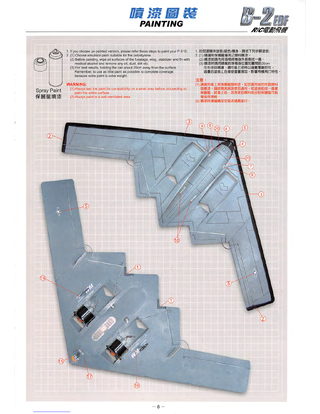
RADIO
GEAR
INSTALLATION
WIRING
AND
CONNECTION
USER'S
CUIDE
i
A'
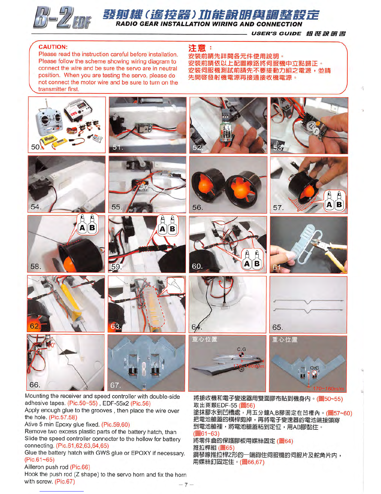
CAUTION:
Please
read
the
instruction
careful
before
installation.
Please
follow
the
scheme
showing
wiring
diagram
to
connect
the
wire
and
be
sure
the
servo
are
in
neutral
position.
When
you
are
testing
the
servo,
please
do
not
connect
the
motor
wire
and
be
sure
to
turn
on
the
transmitter
first.
^ •
It;
V
Mounting the receiver and
speed
controller with double-side
adhesive tapes. (Pic.50-55) , EDF-55x2 (Pic.56)
Applyenough glue to the grooves , then place the wire over
the
hole. (Pic.57.58)
Ative 5 min Epoxy glue fixed. (Pic.59,6G)
Remove two
excess
plastic parts of the battery hatch, than
Slidethe speed controllerconnecter to the
hollow
for battery
connecting. (Pic.61,62,63,64,65)
Gluethe battery hatch
with
GWSglue or
EPOXY
ifnecessary.
(Pic.61~65)
Ailleron push rod (Pic.66)
Hook the push rod (Z
shape)
to the servo horn and fixthe horn
with
screw.
(Pic.67)
_ ^
I
w
SQli/m
=(•50-55)
ffiaiMMEDF-55
(^56)
°(H57-6O)
iij«;1i3lis
' - fflABlPififfi »
(•61-63)
(^64)
Jtatf
$§ (•65)
°(B66,67)