PT-IT
Frame
C
(idf^C)
Plate
3mm
Nut
use
CA
glue
Use
Paper
Tape
Kmmm^
Use
GWS
Glue
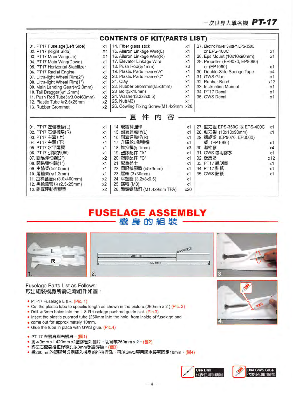
•Insert
the
"C"6 Into
the
slot of
the
fuselage
and
glue Itsecurely. (Pic. 5,6,7,8)
• Apply GWS glue at the Indicated area. For faster cure, you may use a 6-minute epoxy Instead of the Included glue. (Pic.9)
•Once glued, fixin 5 or 6 places using either a very lowtach masking tape or
secure
with tape that
does
not come in
•
contact
with
the
painted
foam,(Pic.10)
which
can
remove
paint.
•
Smm^BMAIBffC.S
> ° (H5,6,7)
•JDHffiAC.e =
(B8)
• o(B9)
• -
(Bio)
POWER
SYSTEM
INSTALLATION
A)
05
S
it
CAUTION:
Before
assemble
the fuselages,
check
which version of power
system
(EPS-350C,
EPS-400C
or
slope
Gllder)you
purchased,
then follow according to that version's power
system
Installation.
•Prepare EPS-350C parts and insert the EPS mount to the electric power system(EPS). Make
sure
that the mount is
pushed into the EPS by 10mm, ifit is too tight to insert the mount, trim the mount slightly with knife or
sand
paper.(Pic.ll)
•
Drill
a 1mm dia. hole by
hand
drill
as
picture 12,
Secured
by a screw. (Pic.12,13)
Put the power system Inthe fuselage upper chamber, making
sure
itfits and is not too tight, then pull itout. Apply glue or
epoxy
and
Install
permanently.(Pic.14,15)
•7ti511]EPS-350C65B)A)l^ffi«fffnB)Al)$R¥si5iii!MJ
•=
(111)
• -
a£!i±¥sItmSJ@^
°(•12,13)
•
)if'
mmmmiMmmTimi:
-
ifi]KB$®»A75iu«05B:otira
°(•14,15)
Use
Drill
Use
Screwdriver
A B
Use
Epoxy
- 5 -