Höcherl & Hackl GmbH Tel.: (+49) 9963 94301 - 0
Indu trie tr. 13 Fax: (+49) 9963 94301 - 84
D-94357 Konzell eMail: upport@hoecherl-hackl.com
Internet: http://www.hoecherl-hackl.com
Manual Ver ion: PL 08 08
Manual Ver ion: PL 08 08Manual Ver ion: PL 08 08
Manual Ver ion: PL 08 08-
--
-21 E
21 E21 E
21 E
1
Höcherl & Hackl
Höcherl & HacklHöcherl & Hackl
Höcherl & Hackl
GmbH
GmbH GmbH
GmbH
Electronic Load Serie
Electronic Load Serie Electronic Load Serie
Electronic Load Serie PL
PLPL
PL
Programming
ProgrammingProgramming
Programming
Content
ContentContent
Content
0
00
0
General Information
General InformationGeneral Information
General Information ................................
................................................................
................................................................
................................................................
.......................................................
..............................................
....................... 3
33
3
1
11
1
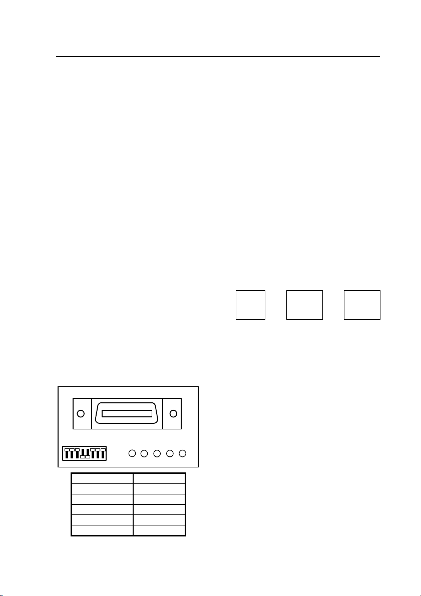
IEEE 488 Int
IEEE 488 IntIEEE 488 Int
IEEE 488 Interface
erfaceerface
erface ................................
................................................................
................................................................
................................................................
..........................................................
....................................................
.......................... 3
33
3
1.1
Setting the IEEE 488 device addre ..............................................................3
1.2
Data format for IEEE 488 .............................................................................3
2
22
2
RS 232 Interface
RS 232 InterfaceRS 232 Interface
RS 232 Interface................................
................................................................
................................................................
................................................................
.............................................................
..........................................................
............................. 4
44
4
2.1
Setting the RS232 Interface...........................................................................4
2.2
Data format for RS232.................................................................................5
3
33
3
H&H Sy tem Bu
H&H Sy tem BuH&H Sy tem Bu
H&H Sy tem Bu ................................
................................................................
................................................................
................................................................
.............................................................
..........................................................
............................. 6
66
6
4
44
4
Sub Addre e
Sub Addre eSub Addre e
Sub Addre e ................................
................................................................
................................................................
................................................................
................................................................
................................................................
................................ 6
66
6
5
55
5
SCPI Syntax
SCPI SyntaxSCPI Syntax
SCPI Syntax................................
................................................................
................................................................
................................................................
................................................................
................................................................
....................................
........
.... 8
88
8
5.1
Common Command ..................................................................................8
5.2
Device Dependent Command .....................................................................8
5.2.1
Header............................................................................................... 8
5.2.1.1
Indention ..........................................................................................................8
5.2.1.2
Alia e ..............................................................................................................8
5.2.2
White Space........................................................................................9
5.2.3
Long and Short Format, Upper and Lower Ca e ....................................9
5.2.4
Optional Keyword ..............................................................................9
5.2.5
Parameter...........................................................................................9
5.2.5.1
Numeric Value <NRf> ....................................................................................9
5.2.5.2
Unit and Multiplier .......................................................................................10
5.2.5.3
Numerical Value and Extreme Value <num>................................................10
5.2.5.4
Boolean Parameter .........................................................................................10
5.2.5.5
Text ................................................................................................................11
5.2.6
The Semicolon ..................................................................................11
5.2.7
Querie ............................................................................................12
6
66
6
Command Overview
Command OverviewCommand Overview
Command Overview ................................
................................................................
................................................................
................................................................
......................................................
............................................
......................13
1313
13
6.1
Common Command ................................................................................13
6.2
Device Dependent Command of the Serie PL ............................................14
7
77
7
Command
Command Command
Command –
––
– Detailled De cription
Detailled De cription Detailled De cription
Detailled De cription ................................
................................................................
................................................................
................................................................
.................................
..
.17
1717
17
7.1
Common Command ................................................................................17
7.2
Device Dependent Command ...................................................................19
7.2.1
Fir t Step .........................................................................................19