manuals.online logo
Brands
  1. Home
  2. •
  3. Brands
  4. •
  5. Höcherl & Hackl
  6. •
  7. Test Equipment
  8. •
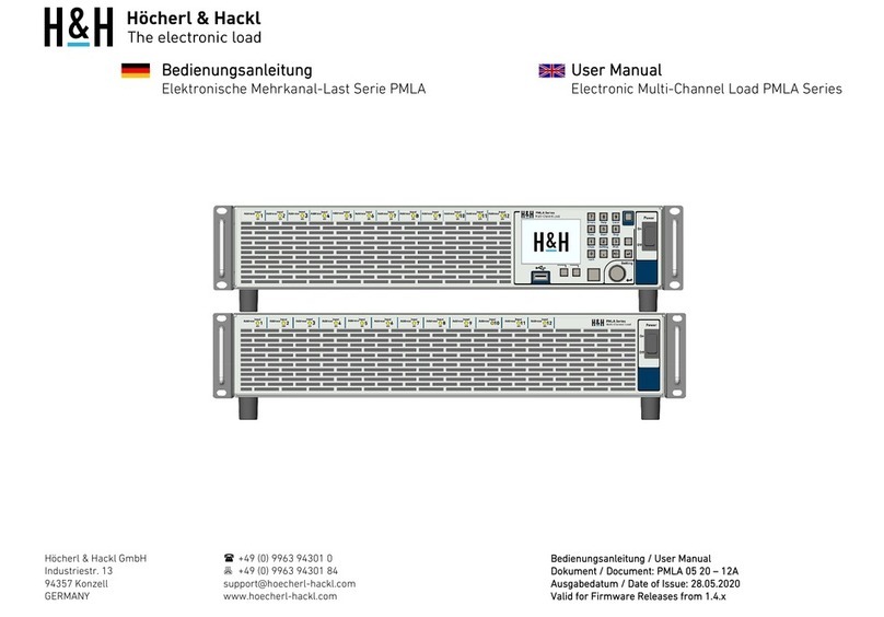
  9. Höcherl & Hackl ZSAC Series Owner's manual

Höcherl & Hackl ZSAC Series Owner's manual

Höcherl & Hackl GmbH Phone: (++49) 9963 94301 - 0
Indu trie tr. 13 Fax: (++49) 9963 94301 - 84
94357 Konzell eMail: upport@hoecherl-hackl.com
Germany Internet: www.hoecherl-hackl.com
Handbuch/
Handbuch/Handbuch/
Handbuch/Manual
Manual Manual
Manual Ver ion:
Ver ion: Ver ion:
Ver ion:
ZSAC 0911
ZSAC 0911ZSAC 0911
ZSAC 0911-
--
-06
0606
06
gültig für/
gültig für/gültig für/
gültig für/valid for
valid forvalid for
valid for Firmware:
Firmware: Firmware:
Firmware:
ZS_SCPI_04.00
ZS_SCPI_04.00 ZS_SCPI_04.00
ZS_SCPI_04.00 ff
ZS_AI_04.03
ZS_AI_04.03ZS_AI_04.03
ZS_AI_04.03 ff
1
Höcherl & Hackl
Höcherl & HacklHöcherl & Hackl
Höcherl & Hackl
GmbH
GmbH GmbH
GmbH
Elektroni che La ten Serie ZSAC
Elektroni che La ten Serie ZSACElektroni che La ten Serie ZSAC
Elektroni che La ten Serie ZSAC
Electronic Load ZSAC Serie
Electronic Load ZSAC SerieElectronic Load ZSAC Serie
Electronic Load ZSAC Serie
Programmierung/
Programmierung/Programmierung/
Programmierung/Programming Manual
Programming ManualProgramming Manual
Programming Manual
Inhalt
InhaltInhalt
Inhalt
1
11
1
Allgemeine
AllgemeineAllgemeine
Allgemeine ................................
................................................................
................................................................
................................................................
................................................................
................................................................
...................................
......
... 5
55
5
1.1
Ein- und Au chalten....................................................................................5
1.2
Remote und Local........................................................................................5
2
22
2
Serielle Schnitt telle
Serielle Schnitt telleSerielle Schnitt telle
Serielle Schnitt telle................................
................................................................
................................................................
................................................................
.........................................................
..................................................
......................... 6
66
6
2.1
Ein tellen der RS232-Parameter....................................................................6
2.2
USB-Schnitt telle..........................................................................................9
2.3
Datenformat bei RS232 und USB ..................................................................9
3
33
3
IEEE 488 Interface
IEEE 488 InterfaceIEEE 488 Interface
IEEE 488 Interface ................................
................................................................
................................................................
................................................................
.........................................................
..................................................
.........................11
1111
11
3.1
Ein tellen der IEEE 488-Geräteadre e ........................................................11
3.2
Datenformat bei IEEE 488 ..........................................................................12
4
44
4
Sy tembu
Sy tembuSy tembu
Sy tembu ................................
................................................................
................................................................
................................................................
................................................................
................................................................
....................................
........
....14
1414
14
5
55
5
Unteradre en
Unteradre enUnteradre en
Unteradre en................................
................................................................
................................................................
................................................................
...............................................................
..............................................................
...............................15
1515
15
5.1
Einzeladre ierung.....................................................................................15
5.2
Blockadre ierung .....................................................................................17
5.3
Sy temadre ierung ...................................................................................19
6
66
6
SCPI
SCPISCPI
SCPI-
--
-Syntax Einführung
Syntax EinführungSyntax Einführung
Syntax Einführung ................................
................................................................
................................................................
................................................................
..................................................
....................................
..................20
2020
20
6.1
Common Command ................................................................................20
6.2
Geräte pezifi che Befehle...........................................................................20
6.2.1
Aufbau de Header ..........................................................................20
6.2.1.1
Einrückungen..................................................................................................21
6.2.1.2
Alia e ............................................................................................................21
6.2.2
White Space......................................................................................22
6.2.3
Lang- und Kurzform, Groß- und Klein chreibung.................................22
6.2.4
Wahlwei e einfügbare Schlü elwörter ................................................23
6.2.5
Parameter.........................................................................................23
6.2.5.1
Zahlenwerte <NRf> .......................................................................................24
6.2.5.2
Einheiten und Multiplizierer .............................................................................24
6.2.5.3
Zahlenwerte und Extremwerte <num> ............................................................25
6.2.5.4
Boole che Parameter.......................................................................................26
6.2.5.5
Text ................................................................................................................27
6.2.6
Benutzung de Semikolon .................................................................27
Höcherl & Hackl GmbH Elektroni che La ten Serie ZSAC
Programmieranleitung
ProgrammieranleitungProgrammieranleitung
Programmieranleitung
Electronic Load ZSAC Serie Programming Manual
Programming ManualProgramming Manual
Programming Manual
2
6.2.7
Abfragebefehle (Querie )...................................................................29
6.3
SCPI Befehl über icht.................................................................................31
6.3.1
Common Command ........................................................................31
6.3.2
Geräte pezifi che Befehle der Serie ZSAC ...........................................32
6.4
SCPI Befehl be chreibung ..........................................................................36
6.4.1
Common Command ........................................................................36
6.4.2
Geräte pezifi che Befehle ..................................................................40
6.4.2.1
Schnellein tieg ................................................................................................40
6.4.2.2
Sub y tem CHANnel|INSTrument ....................................................................42
6.4.2.3
Sub y tem CURRent ........................................................................................44
6.4.2.4
Sub y tem DATA|TRACe .................................................................................50
6.4.2.5
Sub y tem DELay ............................................................................................53
6.4.2.6
Sub y tem GTL ...............................................................................................54
6.4.2.7
Sub y tem INPut|OUTPut ................................................................................55
6.4.2.8
Sub y tem LIST................................................................................................57
6.4.2.9
Sub y tem MEASure ........................................................................................66
6.4.2.10
Sub y tem MODE|FUNCtion...........................................................................70
6.4.2.11
Sub y tem PROGram ......................................................................................72
6.4.2.12
Sub y tem RESi tance......................................................................................76
6.4.2.13
Sub y tem SETup ............................................................................................81
6.4.2.14
Sub y tem SFUNction......................................................................................82
6.4.2.15
Sub y tem STATu ...........................................................................................92
6.4.2.16
Sub y tem SYSTem........................................................................................102
6.4.2.17
Sub y tem TRIGger .......................................................................................115
6.5
Benutzerorientierte Befehl folge ................................................................119
6.5.1
Gerät in Grundzu tand ver etzen......................................................119
6.5.2
Au wahl der Funktion art AC, DC, LINE............................................119
6.5.3
Au wahl der Betrieb art Strom, Wider tand .......................................119
6.5.4
Stromwert ein tellen.........................................................................119
6.5.5
Wider tand wert ein tellen ...............................................................120
6.5.6
Geräteeingang zu- und ab chalten...................................................120
6.5.7
Me en von Strom-, Spannung -, Wider tand - und Lei tung werten...120
6.5.8
Freiprogrammierbare AC-Kurvenform...............................................121
6.5.9
Programm peicher ..........................................................................121
6.5.10
Stromkurve mit Pha enan chnitt........................................................123
6.5.11
Stromkurve mit Oberwellen (Fourier ynthe e).....................................123
6.5.12
Stromkurve mit Cre tfaktor...............................................................123
6.5.13
Pha enver chiebung der Stromkurve.................................................124
6.5.14
Speichern einer Kurvenform in den Intern peicher..............................124
6.5.15
Programmierbare Kurvenform im DC- oder Hüllkurve im AC-Betrieb...125
6.5.16
Me datenerfa ung ........................................................................126
7
77
7
Her teller
Her tellerHer teller
Her teller................................
................................................................
................................................................
................................................................
................................................................
................................................................
....................................
........
....127
127127
127
Höcherl & Hackl GmbH Elektroni che La ten Serie ZSAC
Programmieranleitung
ProgrammieranleitungProgrammieranleitung
Programmieranleitung
Electronic Load ZSAC Serie Programming Manual
Programming ManualProgramming Manual
Programming Manual
3
Table Of Content
Table Of ContentTable Of Content
Table Of Content
1
11
1
General Information
General InformationGeneral Information
General Information ................................
................................................................
................................................................
................................................................
.......................................................
..............................................
....................... 5
55
5
1.1
Power On and Off.......................................................................................5
1.2
Remote and Local........................................................................................5
2
22
2
Serial Interface
Serial InterfaceSerial Interface
Serial Interface ................................
................................................................
................................................................
................................................................
...............................................................
..............................................................
............................... 6
66
6
2.1
Setting the RS232 Parameter .......................................................................6
2.2
USB Interface ..............................................................................................9
2.3
Data Format of the RS232 Interface ..............................................................9
3
33
3
IEEE 488 Interface
IEEE 488 InterfaceIEEE 488 Interface
IEEE 488 Interface ................................
................................................................
................................................................
................................................................
.........................................................
..................................................
.........................11
1111
11
3.1
Setting the IEEE488 Device Addre .............................................................11
3.2
Data Format of the IEEE 488 Interface.........................................................12
4
44
4
Sy tem Bu
Sy tem BuSy tem Bu
Sy tem Bu ................................
................................................................
................................................................
................................................................
................................................................
................................................................
...................................
......
...14
1414
14
5
55
5
Sub Addre e
Sub Addre eSub Addre e
Sub Addre e ................................
................................................................
................................................................
................................................................
...............................................................
..............................................................
...............................15
1515
15
5.1
Single Addre ing ......................................................................................15
5.2
Block Addre ing .......................................................................................17
5.3
Sy tem Addre ing.....................................................................................19
6
66
6
SCPI Syntax Introduction
SCPI Syntax IntroductionSCPI Syntax Introduction
SCPI Syntax Introduction ................................
................................................................
................................................................
................................................................
.................................................
..................................
.................20
2020
20
6.1
Common Command ................................................................................20
6.2
Device Dependent Command ...................................................................20
6.2.1
Header Con truction .........................................................................20
6.2.1.1
Indention .......................................................................................................21
6.2.1.2
Alia e ............................................................................................................21
6.2.2
White Space......................................................................................22
6.2.3
Long and Short Form, Upper and Lower Ca e.....................................22
6.2.4
Optional Keyword ............................................................................23
6.2.5
Parameter .......................................................................................23
6.2.5.1
Numeric Value <NRf> ..................................................................................24
6.2.5.2
Unit and Multiplier .......................................................................................24
6.2.5.3
Numerical Value and Extreme Value <num>................................................25
6.2.5.4
Boolean Parameter .........................................................................................26
6.2.5.5
Text ................................................................................................................27
6.2.6
The Semicolon ..................................................................................27
6.2.7
Querie ............................................................................................29
6.3
SCPI Command Overview..........................................................................31
6.3.1
Common Command ........................................................................31
6.3.2
Device Dependent Command for ZSAC Serie ...................................32
6.4
SCPI Command – Detailed De cription ......................................................36
6.4.1
Common Command ........................................................................36
6.4.2
Device Dependent Command ...........................................................40
6.4.2.1
Fir t Step .......................................................................................................40
6.4.2.2
Sub y tem CHANnel|INSTrument ....................................................................42
6.4.2.3
Sub y tem CURRent ........................................................................................44
6.4.2.4
Sub y tem DATA|TRACe .................................................................................50
6.4.2.5
Sub y tem DELay ............................................................................................53
6.4.2.6
Sub y tem GTL ...............................................................................................54
Höcherl & Hackl GmbH Elektroni che La ten Serie ZSAC
Programmieranleitung
ProgrammieranleitungProgrammieranleitung
Programmieranleitung
Electronic Load ZSAC Serie Programming Manual
Programming ManualProgramming Manual
Programming Manual
4
6.4.2.7
Sub y tem INPut|OUTPut ................................................................................55
6.4.2.8
Sub y tem LIST................................................................................................57
6.4.2.9
Sub y tem MEASure ........................................................................................66
6.4.2.10
Sub y tem MODE|FUNCtion...........................................................................70
6.4.2.11
Sub y tem PROGram ......................................................................................72
6.4.2.12
Sub y tem RESi tance......................................................................................76
6.4.2.13
Sub y tem SETup ............................................................................................81
6.4.2.14
Sub y tem SFUNction......................................................................................82
6.4.2.15
Sub y tem STATu ...........................................................................................92
6.4.2.16
Sub y tem SYSTem........................................................................................103
6.4.2.17
Sub y tem TRIGger .......................................................................................115
6.5
U er-Oriented Command Sequence..........................................................119
6.5.1
Re etting the Device.........................................................................119
6.5.2
Selection of Function AC, DC, LINE...................................................119
6.5.3
Selection of Mode Current, Re i tance...............................................119
6.5.4
Current Setting................................................................................119
6.5.5
Re i tance Setting............................................................................120
6.5.6
Load Input On and Off....................................................................120
6.5.7
Mea uring Current, Voltage, Re i tance and Power Value ................120
6.5.8
U er-Programmable AC Waveform ..................................................121
6.5.9
Program Memory ............................................................................121
6.5.10
Current Waveform With Pha e Control..............................................123
6.5.11
Current Waveform With Harmonic (Fourier Synthe i ) .......................123
6.5.12
Current Waveform With Cre t Factor ................................................123
6.5.13
Pha e Shift of Current Waveform......................................................124
6.5.14
Storing a Waveform into Internal Memory .........................................124
6.5.15
Programmable Waveform in DC or Envelope Curve in AC Mode ........125
6.5.16
Data Acqui ition..............................................................................126
7
77
7
Manufacturer
ManufacturerManufacturer
Manufacturer ................................
................................................................
................................................................
................................................................
..............................................................
............................................................
..............................127
127127
127
Höcherl & Hackl GmbH Elektroni che La ten Serie ZSAC
Programmieranleitung
ProgrammieranleitungProgrammieranleitung
Programmieranleitung
Electronic Load ZSAC Serie Programming Manual
Programming ManualProgramming Manual
Programming Manual
5
1
11
1
Allgemeine
AllgemeineAllgemeine
Allgemeine
1.1
1.11.1
1.1
Ein
EinEin
Ein-
--
- und Au chalten
und Au chalten und Au chalten
und Au chalten
Nach dem Ein chalten durchläuft die
La t eine Initiali ierung routine. Er t
danach können am Gerät Ein tellungen
vorgenommen werden. Die e
Initiali ierung dauert ca. 10 Sekunden,
während die er Zeit ollten keine Befehle
an da Gerät ge chickt werden.
Warten Sie nach dem Au chalten de
Geräte ca. 5 , bi Sie e wieder
ein chalten.
1.2
1.21.2
1.2
Remote und Local
Remote und LocalRemote und Local
Remote und Local
Jeder Befehl, der über eine der
Schnitt tellen im Gerät ankommt – mit
Au nahme von MEAS:xx-Befehlen ( .
SubSy tem MEASure) – chaltet die La t
in Remotezu tand, bei dem keine
manuellen Ein tellungen möglich ind.
Da Gerät kann entweder durch
Drücken der Local-Ta te oder durch
Senden de Befehl GTL wieder in
Handbetrieb gebracht werden.
1
11
1
General Information
General InformationGeneral Information
General Information
1.1
1.11.1
1.1
Power On and
Power On and Power On and
Power On and Off
OffOff
Off
After witching the device on, the
electronic load run an initiali ation
routine which la t approximately 10
econd , no command hould be ent
to the device during thi time.
After witching off the device, plea e
wait 5 before witching it on again.
1.2
1.21.2
1.2
Remote and Local
Remote and LocalRemote and Local
Remote and Local
Any command the device receive by
one of the interface – MEAS:xx
command excepted ( ee SubSy tem
MEASure) – et the load to remote
operation mode where no manual
etting are po ible. The device can be
et to manual operation by pre ing the
Local key or by ending the GTL
command.
Höcherl & Hackl GmbH Elektroni che La ten Serie ZSAC
Programmieranleitung
ProgrammieranleitungProgrammieranleitung
Programmieranleitung
Electronic Load ZSAC Serie Programming Manual
Programming ManualProgramming Manual
Programming Manual
6
2
22
2
Serielle Schnitt telle
Serielle Schnitt telleSerielle Schnitt telle
Serielle Schnitt telle
Die optionale Serielle Schnitt telle
erlaubt die Programmierung der
Elektroni chen La t in der Standard-
Programmier prache SCPI (Standard
Command for Programmable
In trument ).
In der eriellen Schnitt telle werden die
SCPI-Befehle auf da Format de
Sy tembu umgewandelt und im 9Bit-
Adre ierung format an da Analog-
Interface (nicht zu verwech eln mit der
Analog-I/O-Schnitt telle) ge endet,
welche die Befehle letztendlich er t
au führt.
E ind ver chiedene programmierbare
Datenflu teuerung -Methoden
(Hand hake) verfügbar.
Be chreibung . Sub y tem
SYSTem:COMMunication.
2.1
2.12.1
2.1
Ein tellen der RS232
Ein tellen der RS232Ein tellen der RS232
Ein tellen der RS232-
--
-
Parameter
ParameterParameter
Parameter
Die Ein tellungen der RS232-Schnitt telle
werden über die zugehörige DIP-
Schalterreihe konfiguriert. Nachdem ein
oder mehrere DIP-Schalterein tellungen
verändert worden ind, mu da Gerät
au - und einge chaltet werden, um die
neuen Ein tellungen zu übernehmen.
2
22
2
Serial Interface
Serial InterfaceSerial Interface
Serial Interface
The optional erial interface allow the
programming of the electronic load with
tandard programming language SCPI
(Standard Command for
Programmable In trument ).
In the erial interface the SCPI command
tring are converted to the y tem bu
format and tran ferred to the Analog
Interface (don't mix up with Analog I/O
Interface) u ing a 9Bit addre ing
protocol. The Analog Interface execute
the command .
Several programmable flow control
method (hand hake) are available.
De cription ee ub y tem
SYSTem:COMMunication.
2.1
2.12.1
2.1
Setting the RS
Setting the RSSetting the RS
Setting the RS232
232 232
232
Parameter
ParameterParameter
Parameter
The RS232 interface i configured by the
corre ponding DIP witche .
After adju ting one or more of the
RS232 DIP witche the device ha to be
witched off and on, o that the new
etting will be accepted.
Höcherl & Hackl GmbH Elektroni che La ten Serie ZSAC
Programmieranleitung
ProgrammieranleitungProgrammieranleitung
Programmieranleitung
Electronic Load ZSAC Serie Programming Manual
Programming ManualProgramming Manual
Programming Manual
7
Die mit B1 bi B3 bezeichneten Schalter
dienen zur Ein tellung der Baudrate.
Die e wird folgendermaßen codiert:
Baudrate
BaudrateBaudrate
Baudrate
B1
B1B1
B1
B2
B2B2
B2
B3
B3B3
B3
4800 Off Off Off
9600 On Off Off
14400 Off On Off
19200 On On Off
28800 Off Off On
38400 On Off On
57600 Off On On
115200 On On On
Zur Ein tellung der Datenlänge i t der
Schalter 7D vorhanden.
Datenlänge
DatenlängeDatenlänge
Datenlänge
7D
7D 7D
7D
7 Datenbit On
8 Datenbit Off
Die Anzahl der Stop-Bit wird durch den
Schalter 1Stb fe tgelegt:
Stop Bit
Stop BitStop Bit
Stop Bit
1Stb
1Stb 1Stb
1Stb
1 On
2 Off
Ob eine Prüfung der Parität erfolgt, wird
mit dem Schalter P no fe tgelegt.
Parity
ParityParity
Parity
P no
P no P no
P no
Parity on Off
Parity off On
Wie da Parität bit zu bewerten i t,
be timmt Schalter P odd:
Parity
ParityParity
Parity
P odd
P odd P odd
P odd
odd On
even Off
Bei der Au lieferung der Geräte werden
folgende Werk ein tellungen für die
RS232-Schnitt telle gemacht:
The witche B1 to B3 allow to et the
baud rate. They hould have one of the
following etting :
Baud Rate
Baud RateBaud Rate
Baud Rate
B1
B1B1
B1
B2
B2B2
B2
B3
B3B3
B3
4800 Off Off Off
9600 On Off Off
14400 Off On Off
19200 On On Off
28800 Off Off On
38400 On Off On
57600 Off On On
115200 On On On
Switch 7D allow the etting of the data
length.
Data Length
Data LengthData Length
Data Length
7D
7D 7D
7D
7 data bit On
8 data bit Off
The amount of top bit i determined by
the witch 1Stb:
Number of Stop Bit
Number of Stop BitNumber of Stop Bit
Number of Stop Bit
1Stb
1Stb 1Stb
1Stb
1 On
2 Off
Switch Pno determine , whether a parity
check occur .
Parity
ParityParity
Parity
P no
P no P no
P no
Parity on Off
Parity off On
Switch S2 et the parity bit:
Parity
ParityParity
Parity
P odd
P odd P odd
P odd
odd On
even Off
When leaving the factory, the following
etting are activated at the RS232
interface DIP :
Höcherl & Hackl GmbH Elektroni che La ten Serie ZSAC
Programmieranleitung
ProgrammieranleitungProgrammieranleitung
Programmieranleitung
Electronic Load ZSAC Serie Programming Manual
Programming ManualProgramming Manual
Programming Manual
8
B1 = ON, alle anderen OFF, d. h.:
9600 Baud, 8 Datenbit , 2 Stopbit ,
Even Parity
Al RS232-Kabel i t da mitgelieferte
H&H Standard Nullmodem-Kabel mit
RTS-CTS-Hand hake zu verwenden oder
ein nach folgendem
Verdrahtung chema gefertigte Kabel
zu verwenden (Buch e in
Verdrahtung an icht):
B1 = ON, all other OFF, that mean :
9600 Baud, 8 data bit , 2 top bit ,
even parity.
With RS232 communication the hipped
H&H tandard nullmodem cable with
RTS-CTS hand hake or a cable with the
following pin a ignment mu t be u ed
( ocket in wiring view):
H&H Standard Nullmodem Cable
H&H Standard Nullmodem CableH&H Standard Nullmodem Cable
H&H Standard Nullmodem Cable
Die RxD- und TxD-Leitung (Pin 2 und 3)
werden au gekreuzt, d. h. Pin 2 der
linken Buch e wird mit Pin 3 der rechten
verbunden, Pin 3 der linken Buch e wird
mit Pin 2 der rechten verbunden.
Eben o werden die RTS- und CTS-
Leitungen (Pin 7 und 8) au gekreuzt
verdrahtet.
Pin 5 wird durchverdrahtet.
The RxD and TxD line (pin 2 and 3) are
cro -over, i.e. pin 2 of the left ocket i
wired to pin 3 of the right ocket and pin
3 of the left ocket i wired to pin 2 of
the right ocket.
Al o the RTS and CTS line (pin 7 and 8)
are wired cro -over.
Pin 5 i traightly connected from the left
to the right connector.
Höcherl & Hackl GmbH Elektroni che La ten Serie ZSAC
Programmieranleitung
ProgrammieranleitungProgrammieranleitung
Programmieranleitung
Electronic Load ZSAC Serie Programming Manual
Programming ManualProgramming Manual
Programming Manual
9
2.2
2.22.2
2.2
USB
USBUSB
USB-
--
-Schnitt telle
Schnitt telleSchnitt telle
Schnitt telle
Um eine ZSAC La t über die USB-
Schnitt telle an teuern zu können, mu
ein USB-Treiber, der ich auf der
mitgelieferten CD ROM befindet, auf
dem betreffenden PC in talliert werden.
Dazu wird die einge chaltete La t über
ein handel übliche USB-AB-Kabel an
den laufenden PC ange teckt. Der
Computer erkennt die neue Hardware
und fragt nach dem ent prechenden
Treiber. Geben Sie den folgenden Pfad
an:
<CD>:
\USB\u b_driver_ZSAC_ erie _xx\win2k
_xp
Da In tallation programm in talliert
einen "Virtuellen COM-Port" auf dem
PC, de en COM-Port-Nummer im
Gerätemanager der Sy tem teuerung
er ichtlich i t. S. auch COMPORT.PDF
und FTDI Driver In tallation Ap Note for
Win2000.pdf im o.g. Handbuch-CD-
Pfad.
2.3
2.32.3
2.3
Datenformat bei RS232 und
Datenformat bei RS232 und Datenformat bei RS232 und
Datenformat bei RS232 und
USB
USBUSB
USB
Die erielle Schnitt telle erwartet al
Terminierung zeichen (Endekennung)
da Zeichen LF (10 dez.).
Bei erieller Me datenabfrage mu
zwi chen dem Ab enden de
Abfragebefehl und dem Au le en der
Daten eine Wartezeit von minde ten
100m
100m100m
100m
eingehalten werden.
Da Gerät endet al
Terminierung zeichen ebenfall ein LF
(10dez.).
2.2
2.22.2
2.2
USB Interface
USB Interface USB Interface
USB Interface
To control a ZSAC load via the USB
interface a USB driver located on the
hipped CD ROM mu t be in talled on
the concerning PC. To do thi ju t
connect the running load to the running
PC with a u ual USB-AB cable. The
computer detect the new hardware and
a k for the concerning driver. It i
located in the following CD ROM
directory:
<CD>:
\USB\u b_driver_ZSAC_ erie _xx\win2k
_xp
The in tallation program in tall a
"virtual COM port" on the PC which
COM port number can be een in the
Window Control Panel' Device
Manager. See al o COMPORT.PDF and
FTDI Driver In tallation Ap Note for
Win2000.pdf in the above CD path.
2.3
2.32.3
2.3
Data Format of the RS232
Data Format of the RS232 Data Format of the RS232
Data Format of the RS232
Interface
InterfaceInterface
Interface
The RS232 interface expect the
character <LF> (10dec.) a end of
tring ign.
When command are ent to the device
cau ing an an wer (e.g. mea urement )
a delay of at lea t
100m
100m100m
100m
mu t be kept between ending and
receiving data.
After a mea urement data reque t there
i al o ent <LF> (10dec.) a end of
tring ign.
Höcherl & Hackl GmbH Elektroni che La ten Serie ZSAC
Programmieranleitung
ProgrammieranleitungProgrammieranleitung
Programmieranleitung
Electronic Load ZSAC Serie Programming Manual
Programming ManualProgramming Manual
Programming Manual
10
Folgende Leuchtdioden ignali ieren
den Zu tand der eriellen Schnitt telle:
LED Name
LED NameLED Name
LED Name
Bedeutung
BedeutungBedeutung
Bedeutung
REM Remote: Daten-Interface
i t im Fern teuerzu tand,
leuchtet beim er ten
Startbit
RxD Daten-Interface i t beim
Datenempfang
TxD Daten-Interface endet
Daten
ERR Error: Fehler bei der
Datenübertragung (nur
bei RS232)
SYNT SCPI Syntaxfehler (gilt
auch im GPIB-Betrieb)
The following LED how the tatu of
the erial interface:
LED Name
LED NameLED Name
LED Name
Function
FunctionFunction
Function
REM Remote: Data Interface i in
remote tate, light up after
fir t tart bit
RxD Data Interface i receiving
data
TxD Data Interface i ending
data
ERR Error in data tran mi ion
(only at RS232)
SYNT SCPI yntax error (al o for
GPIB operation)
Höcherl & Hackl GmbH Elektroni che La ten Serie ZSAC
Programmieranleitung
ProgrammieranleitungProgrammieranleitung
Programmieranleitung
Electronic Load ZSAC Serie Programming Manual
Programming ManualProgramming Manual
Programming Manual
11
3
33
3
IEEE 488 Interface
IEEE 488 InterfaceIEEE 488 Interface
IEEE 488 Interface
Zu ätzlich zum RS232-Interface kann
da IEEE 488-Interface in die La t
einge teckt werden, welche ebenfall die
Programmierung in SCPI erlaubt. Die
IEEE 488-Schnitt telle beinhaltet
lediglich die erforderliche GPIB
Hardware, die Verarbeitung der SCPI-
Befehle erfolgt im RS232-Interface,
we halb zur Verwendung der IEEE 488-
Schnitt telle immer auch da RS232-
Interface nötig i t.
3
33
3
IEEE 488 Interface
IEEE 488 InterfaceIEEE 488 Interface
IEEE 488 Interface
Additionally to the RS232 interface the
IEEE 488 interface can be in erted into
the load which al o allow the
programming in SCPI yntax. The IEEE
488 interface merely contain the
required GPIB hardware. The proce ion
of the SCPI command happen in the
RS232 interface. Therefore you alway
need al o the RS232 interface with the
IEEE 488 interface.
Ein tellen der Interfaceparame
Ein tellen der InterfaceparameEin tellen der Interfaceparame
Ein tellen der Interfaceparameter
terter
ter
Die IEEE 488-Schnitt tellenkarte kann
über DIP Schalter auf der Ge-
räterück eite einge tellt werden.
3.1
3.13.1
3.1
Ein tellen der IEEE 488
Ein tellen der IEEE 488Ein tellen der IEEE 488
Ein tellen der IEEE 488-
--
-
Geräteadre e
Geräteadre eGeräteadre e
Geräteadre e
Die Ein tellung der IEEE 488
Geräteadre e erfolgt im Binär y tem.
Setting the Interface Parameter
Setting the Interface ParameterSetting the Interface Parameter
Setting the Interface Parameter
The etting of the IEEE488 interface
function i done by u ing the DIP
witche at the back panel of the device.
3.1
3.13.1
3.1
Setting the IEEE488 Device
Setting the IEEE488 Device Setting the IEEE488 Device
Setting the IEEE488 Device
Addre
AddreAddre
Addre
The etting of the IEEE 488 device
addre i provided in the binary
y tem.
Höcherl & Hackl GmbH Elektroni che La ten Serie ZSAC
Programmieranleitung
ProgrammieranleitungProgrammieranleitung
Programmieranleitung
Electronic Load ZSAC Serie Programming Manual
Programming ManualProgramming Manual
Programming Manual
12
Schalter
SchalterSchalter
Schalter
Wert
WertWert
Wert
A1 1
A2 2
A3 4
A4 8
A5 16
Um eine be timmte Adre e einzu tellen,
mu anhand de Werte die Schalter-
tellung ermittelt werden.
Bei piel: Adre e 10
Schalter A4 und A2 auf ON
Bei der Au lieferung i t die IEEE 488
Adre e auf "7" einge tellt, d.h. A1, A2,
A3 auf ON, A4 und A5 auf OFF.
Nachdem ein oder mehrere DIP-
Schalterein tellungen verändert worden
ind, mu da Gerät au - und
einge chaltet werden, um die neuen
Ein tellungen zu übernehmen.
3.2
3.23.2
3.2
Datenformat bei IEEE 488
Datenformat bei IEEE 488 Datenformat bei IEEE 488
Datenformat bei IEEE 488
Bei Betrieb über die IEEE 488-
Schnitt telle können beliebige ASCII-
Zeichen ge endet werden.
Beim Empfang von Daten erwartet da
IEEE 488 Interface eine der folgenden
Kombinationen:
DB
DB DB
DB DB+LF
DB+LF DB+LF
DB+LF DB+LF
DB+LF DB+LF
DB+LF
EOI
EOI EOI
EOI
EOI
EOI EOI
EOI
DB = Datenbyte, LF = Line Feed, EOI =
End or Identify-Leitung
Neben den 5 Adre chaltern itzen 3
weitere Schalter zur Ein tellung der
Endezeichen, die da Gerät beim
Senden (Talken) verwenden oll.
Switch
SwitchSwitch
Switch
Value
ValueValue
Value
A1 1
A2 2
A3 4
A4 8
A5 16
To et a pecific addre , the witch
po ition ha to be determined
depending on the value.
Example: Addre 10
Switch A4 and A2 are et ON
The default addre when leaving the
factory i "7", i.e. A1, A2, A3 at ON
po ition, A4 and A% at OFF po ition.
After adju ting the IEEE 488 device
addre the device ha to be witched
off and on, o that the new device
addre will be accepted.
3.2
3.23.2
3.2
Data Format of the IEEE 488
Data Format of the IEEE 488 Data Format of the IEEE 488
Data Format of the IEEE 488
Interface
InterfaceInterface
Interface
When operating with the IEEE 488
interface any ASCII character may be
ent.
A end of tring ign the IEEE 488
interface expect one of the following
combination :
DB = Data Byte, LF = Line Feed, EOI =
End or Identify
Be ide the 5 addre witche there are
3 further witche which are u ed to et
the termination character when the
device sends data (Talker).
DB
DBDB
DB
EOI
EOIEOI
EOI
DB+LF
DB+LFDB+LF
DB+LF
DB+LF
DB+LFDB+LF
DB+LF
EOI
EOI EOI
EOI
Höcherl & Hackl GmbH Elektroni che La ten Serie ZSAC
Programmieranleitung
ProgrammieranleitungProgrammieranleitung
Programmieranleitung
Electronic Load ZSAC Serie Programming Manual
Programming ManualProgramming Manual
Programming Manual
13
Bei der Au lieferung ind alle
Endezeichen aktiviert (ON).
Wenn in die er Konfiguration Me werte
vom Gerät angefordert wurden, o
liefert da Gerät die Daten in folgendem
Format:
SD.DDDDDDESDD<CR><LF>
SD.DDDDDDESDD<CR><LF>SD.DDDDDDESDD<CR><LF>
SD.DDDDDDESDD<CR><LF>
EOI
EOIEOI
EOI
S: Vorzeichen, + oder -
D: numeri che Stellen
E: Exponent-Zeichen
<CR> Carriage Return
<LF> Line Feed
<EOI> End Or Identify- Leitung
Mit dem letzten aktivierten Endezeichen
(CR oder LF) wird die Leitung EOI
ge etzt, wenn der Schalter "EOI" auf
"ON" teht. I t kein Endezeichen aktiviert
und EOI auf "ON", wird die EOI-Leitung
mit dem letzten Datenbyte ge etzt.
I t weder ein Endezeichen noch EOI
aktiviert, mu da Le en vom Gerät
abhängig von der Anzahl der zu
erwartenden Zeichen beendet werden
(nicht zu empfehlen).
Nachdem ein oder mehrere DIP-
Schalterein tellungen verändert worden
ind, mu da Gerät au - und
einge chaltet werden, um die neuen
Ein tellungen zu übernehmen.
Folgende Leuchtdioden ignali ieren
den Zu tand der IEEE488-Schnitt telle:
LED Name
LED NameLED Name
LED Name
Bedeutung
BedeutungBedeutung
Bedeutung
REM Remote: Daten-Interface
i t im Fern teuerzu tand
LI Li ten: Daten-Interface
i t beim Datenempfang
TA Talk: Daten-Interface
endet Daten
SRQ Service Reque t:
Bedieneranforderung
ge etzt
ERR Error: Fehler bei der
Datenübertragung
When leaving the factory, all termination
character are activated (ON).
When mea urement data have been
reque ted in thi configuration, the
device upplie the data in the following
format:
SD.DDDDDDESDD<CR><LF>
SD.DDDDDDESDD<CR><LF>SD.DDDDDDESDD<CR><LF>
SD.DDDDDDESDD<CR><LF>
E
E E
EOI
OIOI
OI
S: Sign, + or -
D: Numeric digit
E: Exponent
<CR> Carriage Return
<LF> Line Feed
<EOI> End Or Identify Line
The <EOI> line - if activated - i et
with the la t activated termination
character (CR or LF).
If no termination character i activated
and the EOI witch i "ON", the EOI line
will be et with the la t data byte.
If you have activated neither a
termination character nor EOI you mu t
terminate the reading from the device
after the la t data byte (not
recommended!).
After adju ting one of the IEEE 488 DIP
witche the device ha to be witched
off and on, o that the new etting will
be accepted.
The following LED how the tatu of
the IEEE 488 interface:
LED Name
LED NameLED Name
LED Name
Function
FunctionFunction
Function
REM Remote: Data Interface wa
addre ed and i in remote
tate
LI Li ten: Data Interface i
receiving data
TA Talk: Data Interface i
ending data
SRQ Service Reque t i et
ERR An error in the data
tran mi ion occured or
command not allowed
Höcherl & Hackl GmbH Elektroni che La ten Serie ZSAC
Programmieranleitung
ProgrammieranleitungProgrammieranleitung
Programmieranleitung
Electronic Load ZSAC Serie Programming Manual
Programming ManualProgramming Manual
Programming Manual
14
4
44
4
Sy tembu
Sy tembuSy tembu
Sy tembu
Die er Punkt i t nur maßgebend bei der
Steuerung von mehreren Geräten über
eine gemein ame Daten chnitt telle.
Bei Verwendung eine Einzelgeräte in
Verbindung mit einer RS232- oder GPIB-
Schnitt telle i t die er Punkt für da
Ver tändni der Gerätefunktionen nicht
erforderlich. Da Handbuch kann ab
Punkt 6 weiterverfolgt werden.
Bei Verwendung der Sy tembu -Option
ZS04 oder ZS05 können bi zu 192
Geräte über eine gemein ame
IEEE488- oder RS232-Schnitt telle
adre iert werden.
4
44
4
Sy tem Bu
Sy tem BuSy tem Bu
Sy tem Bu
Thi ection applie only for the control
of everal device by the Sy tem Bu .
For u ing a ingle device with RS232 or
GPIB interface thi ection i not
nece ary for under tanding the device
function .
In thi ca e continue the manual with
ection 6.
When operating with the Sy tem Bu
Option ZS04 or ZS05 up to 192 device
can be addre ed by one ingle IEEE488
or RS232 interface.
Die vom Steuerrechner per
Dateninterface ankommenden Daten
werden im Interface auf da Format de
Sy tembu e umgeformt und eriell
durch alle Geräte ge chickt.
The data received from the controlling
computer via IEEE488 or RS232
interface are tran formed into the
format of the Sy tem Bu and are ent
erial through all device .
Höcherl & Hackl GmbH Elektroni che La ten Serie ZSAC
Programmieranleitung
ProgrammieranleitungProgrammieranleitung
Programmieranleitung
Electronic Load ZSAC Serie Programming Manual
Programming ManualProgramming Manual
Programming Manual
15
Me werte, die von den Geräten über
den Sy tembu kommen, werden
wiederum vom Dateninterface auf
ASCII-Format gebracht und an den
Steuerrechner übergeben.
Durch ein Kabel wird der SYS-BUS-
OUTPUT mit dem SYS-BUS-INPUT de
nachfolgenden Geräte verbunden.
ACHTUNG!
ACHTUNG! ACHTUNG!
ACHTUNG!
Bei der Sy tembu ver chaltung mit LW
Bei der Sy tembu ver chaltung mit LWBei der Sy tembu ver chaltung mit LW
Bei der Sy tembu ver chaltung mit LWL
L L
L
(Fiber Optic) darf der SYS
(Fiber Optic) darf der SYS(Fiber Optic) darf der SYS
(Fiber Optic) darf der SYS-
--
-BUS
BUSBUS
BUS-
--
-OUTPUT
OUTPUT OUTPUT
OUTPUT
nur mit dem SYS
nur mit dem SYSnur mit dem SYS
nur mit dem SYS-
--
-BUS
BUSBUS
BUS-
--
-INPUT de
INPUT de INPUT de
INPUT de
nachfolgenden Geräte verbunden
nachfolgenden Geräte verbunden nachfolgenden Geräte verbunden
nachfolgenden Geräte verbunden
werden.
werden.werden.
werden.
5
55
5
Unteradre en
Unteradre enUnteradre en
Unteradre en
5.1
5.15.1
5.1
Einzeladre ierung
Einzeladre ierungEinzeladre ierung
Einzeladre ierung
Um bei der Programmierung die ein-
zelnen Geräte voneinander unter-
cheiden zu können, i t jedem Gerät
eine Unteradre e zugewie en, die an
der DIP-Schalterreihe "Sub Addre "
einge tellt wird. Die Unteradre e i t
binär zu decodieren mit A1 al
niederwertig te Bit. Bei einem
Einzelgerät mu Unteradre e 1
einge tellt werden (A1 ON, alle anderen
OFF):
Mea urement value from the device
ent on the y tem bu are tran ferred
by the SCPI interpreter located on the
RS232 board into ASCII format and ent
to the controlling PC.
The Sy tem IF Output of one device i
connected to the Sy tem IF Input of the
following device by the enclo ed y tem
bu cable.
ATTENTION!
ATTENTION!ATTENTION!
ATTENTION!
The SYS
The SYSThe SYS
The SYS-
--
-BUS Output of a fiber optic
BUS Output of a fiber optic BUS Output of a fiber optic
BUS Output of a fiber optic
y tem may be connected only with the
y tem may be connected only with the y tem may be connected only with the
y tem may be connected only with the
SYS
SYSSYS
SYS-
--
-BUS Input of the following device.
BUS Input of the following device. BUS Input of the following device.
BUS Input of the following device.
5
55
5
Sub Addre e
Sub Addre eSub Addre e
Sub Addre e
5.1
5.15.1
5.1
Single Addre ing
Single Addre ingSingle Addre ing
Single Addre ing
To di tingui h the different device for
programming a ub addre i allocated
for every device which i et at the DIP
witche "Sub Addre " of the Sy tem IF
card. The ub addre i binary coded
with A1 a lea t ignificant bit. When a
device i u ed a a tand-alone device
then ub addre 1 ha to be et (A1
ON, all other OFF):
Höcherl & Hackl GmbH Elektroni che La ten Serie ZSAC
Programmieranleitung
ProgrammieranleitungProgrammieranleitung
Programmieranleitung
Electronic Load ZSAC Serie Programming Manual
Programming ManualProgramming Manual
Programming Manual
16
Die Unteradre e wird nur einmal nach
dem Ein chalten vom DIP-Schalter
gele en. Wird die Unteradre e beim
laufenden Gerät verändert, o mu da
Gerät au - und einge chaltet werden,
um die neue Unteradre e zu
übernehmen.
Unteradre e 0 (alle Sub
Unteradre e 0 (alle Sub Unteradre e 0 (alle Sub
Unteradre e 0 (alle Sub
Addre DIP OFF) i t nicht erlaubt.
Addre DIP OFF) i t nicht erlaubt.Addre DIP OFF) i t nicht erlaubt.
Addre DIP OFF) i t nicht erlaubt.
Um ein be timmte Gerät zu
programmieren, wird dem Gerätebefehl
die ent prechende Unteradre e
vorange tellt.
Um dem Gerät anzuzeigen, daß e ich
dabei um eine Unteradre e handelt,
wird die Zeichenkette "CHANnel" oder
"INSTrument" vor die Nummer ge etzt.
Bei piel zum Ein chalten de Geräte-
eingange :
CHAN 3;INP ON
CHAN 3;INP ONCHAN 3;INP ON
CHAN 3;INP ON
La teingang von Gerät mit der
Unteradre e 3 wird
einge chaltet
CHAN 22;INP ON
CHAN 22;INP ONCHAN 22;INP ON
CHAN 22;INP ON
La teingang von Gerät mit
Unteradre e 22 wird
einge chaltet
Sollen mehrere Kommando an
da elbe Gerät ge endet werden, o
braucht die Unteradre e nur einmal zu
Beginn der Befehl kette gegeben zu
werden.
Bei piel zur Programmierung de
La t trome von 1A mit Ein chalten de
Geräteeingange :
CHAN 3;CURR 1;INP ON
CHAN 3;CURR 1;INP ON CHAN 3;CURR 1;INP ON
CHAN 3;CURR 1;INP ON oder
CHAN 3;:CURR 1;:INP ON
CHAN 3;:CURR 1;:INP ONCHAN 3;:CURR 1;:INP ON
CHAN 3;:CURR 1;:INP ON
Gerät mit der Unteradre e 3 tellt 1A
ein und chaltet den Eingang ein.
The device read the ub addre from
the DIP when it i witched on. When a
device' ub addre i changed while it
i witched on then the device ha to be
witched off and on to recognize the
new ub addre .
Sub addre 0 (all DIP OFF) i
Sub addre 0 (all DIP OFF) i Sub addre 0 (all DIP OFF) i
Sub addre 0 (all DIP OFF) i
not allowed!
not allowed!not allowed!
not allowed!
To program a pecific device the ub
addre i put fir t to the device
command.
To indicate that thi i a ub addre the
tring "CHANnel" or "INSTrument" i put
fir t.
Example: Switching on the device input,
command "INPut ON" i u ed.
CHAN 3;INP ON
CHAN 3;INP ONCHAN 3;INP ON
CHAN 3;INP ON
Load input of device with ub
addre 3 i witched on
CHAN 22;INP ON
CHAN 22;INP ONCHAN 22;INP ON
CHAN 22;INP ON
Load input of device with ub
addre 22 i witched on
When there are everal command to be
ent to one device the econdary
addre only ha to be pecified at the
beginning of the command tring.
Example:
Programming of the load current 1A,
witching the device input on:
CHAN 3;CURR 1;INP ON
CHAN 3;CURR 1;INP ON CHAN 3;CURR 1;INP ON
CHAN 3;CURR 1;INP ON or
CHAN 3;:CURR 1;:INP ON
CHAN 3;:CURR 1;:INP ONCHAN 3;:CURR 1;:INP ON
CHAN 3;:CURR 1;:INP ON
Device with ub addre 3 et
1A and witche the input on.
Höcherl & Hackl GmbH Elektroni che La ten Serie ZSAC
Programmieranleitung
ProgrammieranleitungProgrammieranleitung
Programmieranleitung
Electronic Load ZSAC Serie Programming Manual
Programming ManualProgramming Manual
Programming Manual
17
Eine Zeichenkette kann maximal 512
Zeichen lang ein.
In der Zeichenkette kann auch die
Unteradre e von weiteren Geräten
enthalten ein.
Bei piel:
CHAN 1;:INP ON;:CHAN 2;INP OFF
CHAN 1;:INP ON;:CHAN 2;INP OFFCHAN 1;:INP ON;:CHAN 2;INP OFF
CHAN 1;:INP ON;:CHAN 2;INP OFF
Gerät #1 Eingang ein
Gerät #2 Eingang au
Wenn ein Gerät durch Erkennen der
eigenen Unteradre e einmal adre iert
wurde, o bleibt die er Zu tand erhalten,
bi ein andere Gerät adre iert wird.
Da heißt, da die Befehle vom
adre ierten Gerät olange au geführt
werden, bi durch die Adre ierung
eine anderen Geräte da er te
entadre iert wird.
Bei piel:
CHAN 3;INP ON
CHAN 3;INP ONCHAN 3;INP ON
CHAN 3;INP ON
Gerät #3 wird adre iert
#3 Eingang ein
CURR 1.2
CURR 1.2CURR 1.2
CURR 1.2
Gerät #3 1.2 A
INP OFF
INP OFFINP OFF
INP OFF Gerät #3 Eingang au
CHAN 7;INP ON
CHAN 7;INP ONCHAN 7;INP ON
CHAN 7;INP ON
Gerät #7 wird adre iert
#3 wird entadre iert
#7 Eingang ein
CURR 0.15
CURR 0.15CURR 0.15
CURR 0.15
Gerät #7 0.15 A
5.2
5.25.2
5.2
Blockadre ierung
Blockadre ierungBlockadre ierung
Blockadre ierung
Bei Verwendung einer größeren Anzahl
von Geräten kommt e häufig vor, da
mehrere Geräte mit der gleichen
Ein tellung ver ehen werden mü en.
Dazu i t e ehr um tändlich, jede
Gerät über die Einzeladre ierung zu
programmieren.
A character tring may contain
maximum 512 character .
The econdary addre e from further
device may be contained in the ame
character tring.
Example:
CHAN 1;:INP ON;:CHAN 2;:INP OFF
CHAN 1;:INP ON;:CHAN 2;:INP OFFCHAN 1;:INP ON;:CHAN 2;:INP OFF
CHAN 1;:INP ON;:CHAN 2;:INP OFF
device #1 input on
device #2 input off
When a device ha been addre ed by a
econdary addre , thi tatu remain
con tant until another device will be
addre ed.
That mean , the command from the
addre ed device are executed until
another device i addre ed o that the
fir t device i de-addre ed.
Example:
CHAN 3;INP ON
CHAN 3;INP ONCHAN 3;INP ON
CHAN 3;INP ON
device #3 Input on
#3 i addre ed
CURR 1.2
CURR 1.2CURR 1.2
CURR 1.2
device #3 1.2 A
INP OFF
INP OFFINP OFF
INP OFF device #3 input off
CHAN 7;INP ON
CHAN 7;INP ONCHAN 7;INP ON
CHAN 7;INP ON
device #7 input on
#3 i de-addre ed
#7 i addre ed
CURR 0.15
CURR 0.15CURR 0.15
CURR 0.15
device #7 0.15 A
5.2
5.25.2
5.2
Block Addre ing
Block Addre ingBlock Addre ing
Block Addre ing
For u e of everal device it often occur
that a group of device have to be
adju ted with the ame etting.
It i very toil ome to addre every ingle
device by di crete addre ing.
Höcherl & Hackl GmbH Elektroni che La ten Serie ZSAC
Programmieranleitung
ProgrammieranleitungProgrammieranleitung
Programmieranleitung
Electronic Load ZSAC Serie Programming Manual
Programming ManualProgramming Manual
Programming Manual
18
Hier i t die Blockadre ierung eine
komfortablere Methode, einer
umgrenzten Gruppe von Geräten die
gleichen Befehle au führen zu la en.
Dazu werden eine Anfang - und eine
Endadre e angegeben, die durch einen
Doppelpunkt (:) getrennt ind.
Bei piel:
CHAN 3:15;INP ON
CHAN 3:15;INP ONCHAN 3:15;INP ON
CHAN 3:15;INP ON
Gerät 3 bi Gerät 15 Eingang
ein chalten
CHAN 20:50;INP OFF
CHAN 20:50;INP OFFCHAN 20:50;INP OFF
CHAN 20:50;INP OFF
Gerät 20 bi Gerät 50 Eingang
au chalten
Werden die Blockgrenzen nicht
auf teigend programmiert, dreht der
SCPI-Interpreter im Digital-Interface die
Reihenfolge automati ch um, o da
beide folgende Blockangaben möglich
ind:
CHAN 8:3
CHAN 8:3CHAN 8:3
CHAN 8:3
C
CC
CHAN 3:8
HAN 3:8HAN 3:8
HAN 3:8
Ent prechend wie bei der
Einzeladre ierung bleibt auch der
Zu tand der Adre ierung für einen
Block erhalten, bi einzelne Geräte oder
ein anderer Block neu adre iert
werden.
Die Blockadre ierung i t bei
Kommando , die eine Antwort de
Geräte au lö en (z.B. Me funktionen),
wegen möglicher Kolli ion der
Me daten unzulä ig. De halb werden
bei Abfragen in Blockadre ierung keine
Daten vom Gerät ge endet.
Group addre ing i a comfortable way
to in truct a group of device to execute
the ame command . For thi purpo e,
a tart and end addre i et, eparated
by a colon (:).
Example:
CHAN 3:15;INP ON
CHAN 3:15;INP ONCHAN 3:15;INP ON
CHAN 3:15;INP ON
Device 3 to device
15 input on
CHAN 20
CHAN 20CHAN 20
CHAN 20:50;INP OFF
:50;INP OFF:50;INP OFF
:50;INP OFF
Device 20 to device
50 input off
The SCPI interpreter automatically re-
order block boundarie if they are not
programmed in a cending order.
Therefore both of the following
command are valid:
CHAN 8:3
CHAN 3:8
Analog to the di crete addre ing the
tatu of the addre ing for a group
remain con tant, until ingle device or
other group of device are addre ed.
The group addre ing i not allowed for
command that require an an wer of a
device (mea urement and tatu
function ), becau e the mea urement
data could collide with each other.
Höcherl & Hackl GmbH Elektroni che La ten Serie ZSAC
Programmieranleitung
ProgrammieranleitungProgrammieranleitung
Programmieranleitung
Electronic Load ZSAC Serie Programming Manual
Programming ManualProgramming Manual
Programming Manual
19
5.3
5.35.3
5.3
Sy temadre ierung
Sy temadre ierungSy temadre ierung
Sy temadre ierung
Zum Adre ieren aller ange chlo enen
Geräte i t die Sy temadre e 0
vorge ehen.
Wird einem Kommando die
Sy temadre e 0 vorange tellt, o wird
da Kommando von allen am Sy tembu
ange chlo enen Geräten au geführt.
Be onder nützlich i t die Sy temadre e,
wenn z.B. alle Geräte in den
Grundzu tand ver etzt werden ollen.
Bei piel:
CHAN 0;*RST
CHAN 0;*RSTCHAN 0;*RST
CHAN 0;*RST Sy tem-Re et
Die Sy temadre ierung i t bei
Kommando , die eine Antwort de
Geräte au lö en (z.B. Me funktionen),
wegen möglicher Kolli ion der
Me daten unzulä ig. De halb werden
bei Abfragen bei Sy temadre ierung
keine Daten vom Gerät ge endet.
5.3
5.35.3
5.3
Sy tem Addre ing
Sy tem Addre ingSy tem Addre ing
Sy tem Addre ing
To addre all connected device , the
y tem addre 0 i provided.
When a command put fir t the y tem
addre 0, the command will be
executed from all device that are
connected to the y tem bu . Thi i
e pecially u eful when all device have
to be re et.
Example:
CHAN 0;*RST
CHAN 0;*RSTCHAN 0;*RST
CHAN 0;*RST Sy tem Re et
The y tem addre ing i not allowed for
command that require an an wer of a
device (mea urement and tatu
function ), becau e the mea urement
data could collide with each other.
Therefore a device won't end any
an wer in y tem addre ing mode.
Höcherl & Hackl GmbH Elektroni che La ten Serie ZSAC
Programmieranleitung
ProgrammieranleitungProgrammieranleitung
Programmieranleitung
Electronic Load ZSAC Serie Programming Manual
Programming ManualProgramming Manual
Programming Manual
20
6
66
6
SCPI
SCPISCPI
SCPI-
--
-Syntax
Syntax Syntax
Syntax
Einführung
EinführungEinführung
Einführung
Der SCPI-Standard (Standard Comm-
and for Programmable In trument )
be chreibt einen einheitlichen Befehl -
atz zur Programmierung von Geräten,
unabhängig von Gerätetyp und
Her teller. E ollen damit die geräte-
pezifi chen Befehle vereinheitlicht
werden.
6.1
6.16.1
6.1
Com
ComCom
Common Command
mon Commandmon Command
mon Command
Common Command ind geräte-
unabhängige Befehle, die in der Norm
IEEE488.2 definiert werden. Sie
be tehen au einem Stern (*) und drei
Buch taben mit evtl. folgendem
Parameter.
Abfragebefehle werden durch Anhängen
eine Fragezeichen gebildet.
Bei piele:
*RST Re et; Gerät in Grundzu tand
ver etzen
*ESE 9 Bit 0 und 3 in ESE-Regi ter
etzen
*IDN? Identifikation tring le en
6.2
6.26.2
6.2
Geräte pezifi che Befehle
Geräte pezifi che BefehleGeräte pezifi che Befehle
Geräte pezifi che Befehle
6.2.1
6.2.16.2.1
6.2.1
Aufbau de Header
Aufbau de HeaderAufbau de Header
Aufbau de Header
Die Struktur der geräte pezifi chen Be-
fehle i t hierarchi ch aufgebaut.
Ein Befehl be teht au einem og.
Header und eventuell einem oder
mehreren folgenden Parametern, durch
ein "White Space" ( .u.) vom Header
getrennt.
Der Header be teht au einem oder
mehreren Schlü elwörtern, die
wiederum durch einen Doppelpunkt (:)
voneinander getrennt werden.
6
66
6
SCPI Syntax
SCPI Syntax SCPI Syntax
SCPI Syntax
Introduction
IntroductionIntroduction
Introduction
The SCPI Standard (Standard
Command for Programmable
In trument ) include a tandardized
command et for programming device ,
independent of device type and
manufacturer. In thi way the device
dependent command are unified.
6.1
6.16.1
6.1
Common Command
Common CommandCommon Command
Common Command
Common Command are device
independent command that are defined
in the tandard IEEE488.2. They include
an a teri k (*) and three letter with
optional parameter.
Query command are built by po t-
fixing a que tion mark.
Example :
*RST Re et
*ESE 9 Set Bit 0 and 3 in ESE
*IDN? Read identification tring
6.2
6.26.2
6.2
Device Dependent
Device Dependent Device Dependent
Device Dependent
Co
CoCo
Com
mm
mmand
mandmand
mand
6.2.1
6.2.16.2.1
6.2.1
Header Con truction
Header Con tructionHeader Con truction
Header Con truction
The device dependent command are
hierarchically tructured.
A command contain a o called
Header a well a one or more
parameter , eparated by a white pace
from the header.
The header contain one or more
keyword , that are eparated by a colon
(:).

Other Höcherl & Hackl Test Equipment manuals

Höcherl & Hackl PL Series Owner's manual

Höcherl & Hackl

Höcherl & Hackl PL Series Owner's manual

Höcherl & Hackl PMLA Series User manual

Höcherl & Hackl

Höcherl & Hackl PMLA Series User manual

Popular Test Equipment manuals by other brands

REV Ritter GK26A operating instructions

REV Ritter

REV Ritter GK26A operating instructions

unotec DRIVE-4-ALL manual

unotec

unotec DRIVE-4-ALL manual

Ametek Teseq NSG 3150 user manual

Ametek

Ametek Teseq NSG 3150 user manual

Scientific SMO5000X Series user manual

Scientific

Scientific SMO5000X Series user manual

Hioki BT3563A instruction manual

Hioki

Hioki BT3563A instruction manual

BT 301B Handbook

BT

BT 301B Handbook

YOKOGAWA DLM3022 user manual

YOKOGAWA

YOKOGAWA DLM3022 user manual

Rigol MS05000-4CH user guide

Rigol

Rigol MS05000-4CH user guide

Ossila T2003 user manual

Ossila

Ossila T2003 user manual

az-instrument 8930 Operation manual

az-instrument

az-instrument 8930 Operation manual

Compliance West HT-S Series instruction manual

Compliance West

Compliance West HT-S Series instruction manual

BIRD AT-800 Operation manual

BIRD

BIRD AT-800 Operation manual

IDEAL Networks LanXPLORER manual

IDEAL Networks

IDEAL Networks LanXPLORER manual

Fluke CertiFiber Pro user manual

Fluke

Fluke CertiFiber Pro user manual

Meatest M505D Operation manual

Meatest

Meatest M505D Operation manual

insize ISH-RD200 manual

insize

insize ISH-RD200 manual

Webasto Hollandia 900 Installation, operation and maintenance manual

Webasto

Webasto Hollandia 900 Installation, operation and maintenance manual

Scott Fetzer Meriam M1000 user manual

Scott Fetzer

Scott Fetzer Meriam M1000 user manual

manuals.online logo
manuals.online logoBrands
  • About & Mission
  • Contact us
  • Privacy Policy
  • Terms and Conditions

Copyright 2025 Manuals.Online. All Rights Reserved.