WIKA CPH8000-ET User manual

Hand-held multifunction calibrator CPH8000-ET and CPH8000/IS-ET/IS
EN
Documenting Multivariable Multichannel Calibrator CPH8000 - ET and CPH8000/IS - ET/IS
Operating instructions

2WIKA operating instructions, CPH8000 - ET and CPH8000/IS -ET/IS
EN
Operating instructions CPH8000 –CPH8000ET
Page
5 - 95
Rev. 00 –July 2020
© 2020 WIKA Alexander Wiegand SE & Co. KG
All rights reserved. / Alle Rechte vorbehalten.
WIKA® is a registered trademark in various countries.
Prior to starting any work, read the operating instructions!
Keep for later use!

Content
WIKA operating instructions, CPH8000 - ET and CPH8000/IS - ET/IS 3
EN
1GENERAL INFORMATION..................................................................................................5
2SAFETY...............................................................................................................................6
2.1 Explanation of symbols.......................................................................................................................... 6
2.2 Intended use.......................................................................................................................................... 7
2.3 Personnel qualification........................................................................................................................... 7
2.4 Additional safety instructions for instruments with ATEX approval only CPH8000/IS -ET/IS............... 8
2.5 Special hazards ..................................................................................................................................... 9
2.6 Labelling / safety marks....................................................................................................................... 10
3SPECIFICATIONS .............................................................................................................11
3.1 Base instrument................................................................................................................................... 11
3.2 Certificates........................................................................................................................................... 12
3.3 Pressure module.................................................................................................................................. 12
3.3.1 Internal sensors................................................................................................................................ 12
3.3.2 External pressure sensor CPT8100................................................................................................. 13
3.4 Electrical signals.................................................................................................................................. 14
3.4.1 Electrical input signals...................................................................................................................... 14
3.4.2 Electrical output signals ................................................................................................................... 14
3.4.3 HART module................................................................................................................................... 15
3.5 Resistance thermometer measurement .............................................................................................. 16
3.6 Resistance thermometer simulation .................................................................................................... 17
3.7 Thermocouple measurement............................................................................................................... 18
3.8 Thermocouple simulation..................................................................................................................... 18
3.9 Environmental parameters module...................................................................................................... 19
3.10 CPH8000 –IS Dimension in mm (in)................................................................................................... 20
3.10.1 Case for instrument model CPH8000 - /IS....................................................................................... 20
3.10.2 Front panel of model CPH8000 - /IS................................................................................................ 20
3.10.3 Case for instrument model CPH8000ET - ET/IS ............................................................................. 21
3.10.4 Front panel of model CPH8000 ET - ET/IS...................................................................................... 21
4DESIGN AND FUNCTION .................................................................................................22
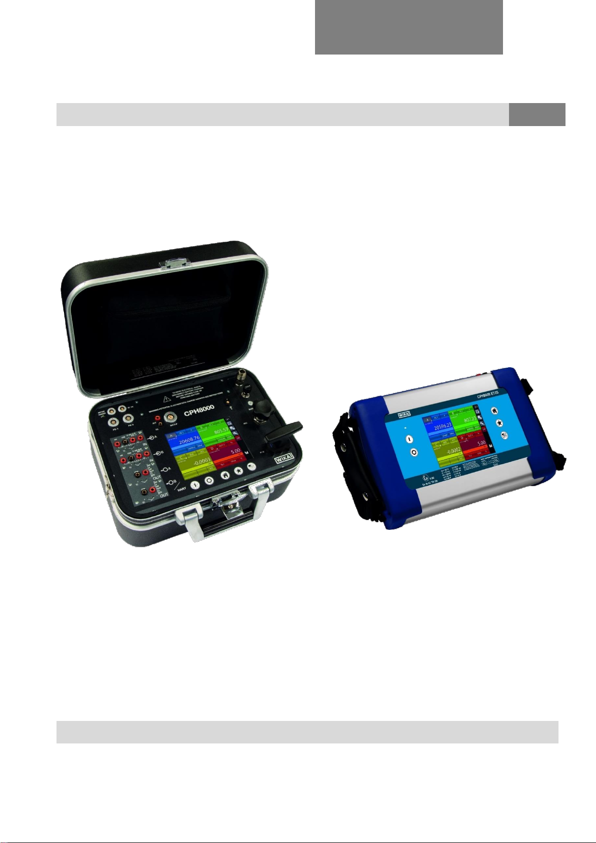
4.1 Description........................................................................................................................................... 22
4.2 Scope of delivery ................................................................................................................................. 24
4.3 Power supply ....................................................................................................................................... 24
4.3.1 Smart Power Supply & Battery Charger model 212009................................................................... 24
4.3.2 Safety instruction.............................................................................................................................. 25
4.3.3 Liability Disclaimer............................................................................................................................ 25
4.3.4 LED status Functionalities................................................................................................................ 25
4.3.5 Operating the device........................................................................................................................ 26
4.3.6 Care and Maintenance..................................................................................................................... 26
4.3.7 Technical Specifications................................................................................................................... 26
5TRANSPORT, PACKAGING AND STORAGE ..................................................................27
5.1 Trasport................................................................................................................................................ 27
5.2 Packaging............................................................................................................................................ 27
5.3 Storage ................................................................................................................................................ 27
6COMMISSIONING, OPERATION ......................................................................................28
6.1 Commissioning .................................................................................................................................... 28
6.1.1 Instrument overview CPH8000 - /IS................................................................................................. 28
6.1.2 Instrument overview CPH8000ET - ET/IS........................................................................................ 29
6.1.3 Functional Modules.......................................................................................................................... 30
6.1.3.1 Input module for electrical/temperature signals............................................................................... 30
6.1.3.2 Output module for electrical/temperature signals............................................................................ 30
6.1.3.3 Pressure module.............................................................................................................................. 30
6.1.3.4 HART module .................................................................................................................................. 31
6.1.3.5 Environmental parameters module (optional).................................................................................. 33
6.2 Pressure............................................................................................................................................... 33
6.2.1 Pneumatic circuit CPH8000 - /IS (not avaiilable for CPH8000ET- ET/IS)....................................... 33
6.3 Electrical section.................................................................................................................................. 35
6.3.1 Misure segnali elettrici...................................................................................................................... 35

Content
4WIKA operating instructions, CPH8000 - ET and CPH8000/IS -ET/IS
EN
6.3.2 Thermocouple measurements ......................................................................................................... 35
6.3.3 Resistance thermometer measurements......................................................................................... 35
6.3.4 Generation of electrical parameters................................................................................................. 35
6.3.5 Thermocouple simulation................................................................................................................. 35
6.3.6 Resistance thermometer simulation................................................................................................. 35
6.4 User interface ...................................................................................................................................... 36
6.4.1 Channel configuration ...................................................................................................................... 39
6.4.2 Other assignments........................................................................................................................... 44
6.4.2.1 Pressure measurement ................................................................................................................... 44
6.4.2.2 Thermocouple signal measurement................................................................................................ 48
6.4.2.3 Electrical parameter measurement.................................................................................................. 50
6.4.2.4 Temperature Simulation .................................................................................................................. 52
6.4.2.5 Electrical parameter generation....................................................................................................... 53
6.4.2.6 Channel D –mathematic functions.................................................................................................. 53
6.4.2.7 HART channel assignment.............................................................................................................. 57
6.4.2.8 HART trimmer calibration ................................................................................................................ 60
6.4.2.9 HART scale adjust........................................................................................................................... 61
6.5 Setting channel, function, instrument .................................................................................................. 62
6.5.1 Channel setting ................................................................................................................................ 62
6.5.2 Functions setting.............................................................................................................................. 65
6.5.3 Instrument setting............................................................................................................................. 66
6.5.3.1 Setting the “F“ key of the keyboard ................................................................................................. 66
6.5.3.2 Setting the Password field............................................................................................................... 67
6.5.3.3 Instrument status page.................................................................................................................... 68
6.6 Channel settings.................................................................................................................................. 68
6.6.1 OFFSET ON –OFFSET OFF .......................................................................................................... 68
6.6.2 SCALING.......................................................................................................................................... 69
6.6.3 HOLD ON –HOLD OFF................................................................................................................... 70
6.6.4 FILTER............................................................................................................................................. 70
6.6.5 RAMP............................................................................................................................................... 71
6.6.6 Modification of the generation/simulation value............................................................................... 72
6.7 REPORT.............................................................................................................................................. 73
6.7.1 Report of Tc/Rtd with dry well calibrator or dry block management ................................................ 80
6.8 CPH8000 Report Software.................................................................................................................. 84
6.9 Data Logger......................................................................................................................................... 87
6.10 Communication.................................................................................................................................... 89
6.11 Calibration examples........................................................................................................................... 90
6.11.1 Example 1 –Calibration of 2-wire pressure transmitters................................................................. 90
6.11.2 Example 2 –Calibration of PTZ gas volume converters.................................................................. 91
6.11.3 Example 3 –Calibration of 4-wire RTD’s ......................................................................................... 92
6.11.4 Example 4 - Calibration of a two-wire temperature transmitter with 3 or 4-wire resistance
thermometer input............................................................................................................................ 93
6.11.5 Example 5 –Calibration of Thermocouples..................................................................................... 94
6.11.6 Example 6 - Calibration of a two-wire temperature transmitter with thermocouple input ................ 95
7MAINTENANCE, CLEANING AND SERVICING ...............................................................96
7.1 Maintenance ........................................................................................................................................ 96
7.2 Cleaning............................................................................................................................................... 96
7.3 Recalibration........................................................................................................................................ 96
8DISMOUNTIG, RETURN AND DISPOSAL........................................................................97
8.1 Dismounting......................................................................................................................................... 97
8.2 Return.................................................................................................................................................. 97
8.3 Disposal............................................................................................................................................... 97
You can find the declarations of conformity online on the website www.wika.com

1 General information
WIKA operating instructions, CPH8000 - ET and CPH8000/IS - ET/IS 5
EN
1 General information
■The models CPH8000 - ET or CPH8000/IS -ET/IS hand-held multifunction calibrator described in
the operating instructions has been manufactured using state-of-the-art technology. All
components are subject to stringent quality and environmental criteria during production. Our
management systems are certified to ISO 9001 and ISO 14001
■These operating instructions contain important information on handling the Multichannel
Calibrator model CPH8000 - ET or CPH8000/IS -ET/IS. Working safely requires that all safety
instructions and work instructions are observed.
■Observe the relevant local accident prevention regulations and general safety regulations for the
range of use of the Multichannel Calibrator model CPH8000 - ET or CPH8000/IS -ET/IS.
■The operating instructions are part of the product and must be kept in the immediate vicinity of
the Multichannel Calibrator model CPH8000 - ET or CPH8000/IS -ET/IS and readily accessible to
skilled personnel at any time.
■Skilled personnel must have carefully read and understood the operating instructions prior to
beginning any work.
■The manufacturer's liability is void in the case of any damage caused by using the product
contrary to its intended use, non-compliance with these operating instructions, assignment of
insufficiently qualified skilled personnel or unauthorized modifications to the CPH8000 - ET or
CPH8000/IS -ET/IS
■The general terms and conditions contained in the sales documentation shall apply.
■Subject to technical modifications.
■Factory calibrations / DKD/DAkkS calibrations are carried out in accordance with international
standards.
■Further information:
- Internet address: www.wika.de / www.wika.com
- Relevant data sheet: CT 18.03
- Application consultant: Tel.: +49 9372 132-0
Fax: +49 9372 132-406
E-Mail: info@wika.com

2 Safety
6WIKA operating instructions, CPH8000 - ET and CPH8000/IS -ET/IS
EN
2 Safety
2.1 Explanation of symbols
DANGER!
... indicates a directly dangerous situation resulting in serious injury or death, if not
avoided.
Information
... points out useful tips, recommendations and information for efficient and trouble-free
operation.
WARNING!
... indicates a potentially dangerous situation in a potentially explosive
atmosphere, resulting in serious injury or death, if not avoided
WARNING!
Before installation, commissioning and operation, ensure that the appropriate reference
pressure sensor has been selected in terms of measuring range, design and specific
measuring conditions. Serious injuries and/or damage can occur should these not be
observed.
Further important safety instructions can be found in the individual chapters of these
operating instruction.

2 Safety
WIKA operating instructions, CPH8000 - ET and CPH8000/IS - ET/IS 7
EN
2.2 Intended use
The Multichannel Calibrator model CPH8000 - ET or CPH8000/IS -ET/IS can be used as a calibration
instrument and also for any application which requires an accurate pressure measurement.
The Multichannel Calibrator model CPH8000 - ET or CPH8000/IS -ET/IS has been designed and built
solely for the intended use described here, and may only be used accordingly.
The technical specifications contained in these operating instructions must be observed.
Improper handling or operation of the Multichannel Calibrator model CPH8000 - ET or CPH8000/IS -
ET/IS outside of its technical specifications requires the instrument to be taken out of service immediately
and inspected by an authorized WIKA service engineer.
Handle electronic precision measuring instruments with the required care (protect from humidity, impacts,
strong magnetic fields, static electricity and extreme temperatures, do not insert any objects into the
instrument or its openings). Plugs and sockets must be protected from contamination.
If the Multichannel Calibrator model CPH8000 - ET or CPH8000/IS -ET/IS are transported from a cold
into a warm environment, the formation of condensation may result in the instrument malfunctioning.
Before putting it back into operation, wait for the instrument temperature and the room temperature to
equalize.
The manufacturer shall not be liable for claims of any type based on operation contrary to the intended
use.
2.3 Personnel qualification
WARNING!
Risk of injury should qualification be insufficient
Improper handling can result in considerable injury and damage to equipment.
■The activities described in these operating instructions may only be carried out
by skilled personnel who have the qualifications described below
Skilled personnel
Skilled personnel, authorized by the operator, are understood to be personnel who, based on their
technical training,
knowledge of measurement and control technology and on their experience and knowledge of country-
specific regulations, current standards and directives, are capable of carrying out the work described and
independently recognizing potential hazards.
Special operating conditions require further appropriate knowledge, e.g. of aggressive media.

2 Safety
8WIKA operating instructions, CPH8000 - ET and CPH8000/IS -ET/IS
EN
2.4 Additional safety instructions for instruments with ATEX approval only CPH8000/IS -ET/IS
WARNING!
Non-observance of these instructions and their contents may result in the loss of
explosion protection.
■Battery operation:
Use only the rechargeable battery which is supplied by WIKA! Only charge the battery
outside of the hazardous area!
■Operation of the serial interface in the hazardous area is prohibited.
Further hazardous area safety instructions!
Observe the operating information and the relevant country-specific regulations
concerning use in hazardous areas (e.g. EN IEC 60079-14).
The CPH8000/IS-ET/IS intrinsically safe multichannel calibrator has been designed for
use in Ex Hazardous Areas. These are areas where potentially flammable or explosive
vapors may occur. These areas are referred to as hazardous (classified) locations in the
United States, as Hazardous Locations in Canada, as Potentially Explosive Atmospheres
in Europe and as Explosive Gas Atmospheres by most of the rest of the world. The
CPH8000/IS-ET/IS intrinsically safe multichannel calibrator is designed as intrinsically
safe. This means that connecting the CPH8000/IS-ET/IS intrinsically safe multichannel
calibrator to equipment that is used within intrinsically safe circuits will not cause an
ignition capable arc as long as the entity parameters are suitably matched.
Information/Approval for hazardous locations:
WARNING!
■Ex Hazardous Areas
An Ex-hazardous area as used in this manual refers to an area made hazardous by the
potential presence of flammable or explosive vapors. These areas are also referred to
as hazardous locations.
WARNING!
Only gauges powered by batteries are approved for use in hazardous locations.
Use only the rechargeable battery which is supplied by WIKA! Only charge the
battery outside of the hazardous area!
II 2G
Ex ib IIC T4 Gb - Tamb -10° C - 50° C

2 Safety
WIKA operating instructions, CPH8000 - ET and CPH8000/IS - ET/IS 9
EN
2.5 Special hazards
WARNING!
■When measuring pressure, make sure that the process pressure line is shut
off and depressurized before it is connected to or disconnected from the
pressure module.
■Disconnect test leads before changing to another measurement or generation
function.
■Observe the working conditions in accordance with chapter "3. Specifications".
■Always operate the device within its overload limits.
■To ensure problem-free operation, only operate the Multichannel Calibrator
model CPH8000/IS-ET/IS on battery power. Only use the mains connection
for charging the Hand-held pressure calibrators batteries.
■Do not apply a voltage greater than the specified voltage to the instrument.
See chapter "3. Specifications".
■Make sure that the test probes never contact a voltage source while the test
leads are connected to the current terminals.
■Do not use the calibrator if it is damaged. Before using the multichannel
calibrator, check that there are no cracks or missing plastic parts on the case.
Pay particular attention to the insulation of the connectors.
■Select the proper function and correct measuring range for the measurement.
■Inspect the test leads for damaged insulation or exposed metal. Check the
continuity of the test leads. Damaged test leads should be replaced before
using the multichannel calibrator.
■When using test probes keep fingers away from the test probe contacts. Keep
your fingers behind the test probes' finger guards.
■First connect the common lead, and then the live lead. When disconnecting,
remove the live test lead first.
■Do not use the multichannel calibrator if it is not working properly. The
instrument protection might be compromised. If in doubt, have the instrument
checked.
■Do not operate the calibrator in areas with explosive gases, vapours or dust.
■To avoid false readings, which could lead to possible electric shock or
personal injury, charge the rechargeable battery as soon as the battery
indicator appears.
■In order to avoid any possible damage to the multichannel calibrator or the
test equipment, use the correct leads, the correct function and the correct
range for the measuring application.

2 Safety
10 WIKA operating instructions, CPH8000 - ET and CPH8000/IS -ET/IS
EN
2.6 Labelling / safety marks
Explanation of symbols
CPH8000 - ET and CPH8000/IS - ET/IS
Before mounting and commissioning the Multichannel Calibrator model CPH8000 - ET
or CPH8000/IS -ET/IS, ensure you read the operating instructions!
CE, European Community
Instruments bearing this mark comply with the relevant European directives.
This marking on the instruments indicates that they must not be disposed of in
domestic waste. The disposal is carried out by return to the manufacturer or by the
corresponding municipal authorities. See Directive 2002/96/EC
Only CPH8000/IS -ET/IS
ATEX European Explosion Protection Directive
(Atmosphère = AT, explosible = Ex)
Instruments bearing this mark comply with the requirements of the European
Directive 94/9/CE (ATEX) on explosion protection.
IECEx for IEC 60079-0, IEC 60079-11

3 Specifications
WIKA operating instructions, CPH8000 - ET and CPH8000/IS - ET/IS 11
EN
3 Specifications
3.1 Base instrument

3 Specifications
12 WIKA operating instructions, CPH8000 - ET and CPH8000/IS -ET/IS
EN
3.2 Certificates
3.3 Pressure module
3.3.1 Internal sensors

3 Specifications
WIKA operating instructions, CPH8000 - ET and CPH8000/IS - ET/IS 13
EN
3.3.2 External pressure sensor CPT8100
Figure 1 –External pressure sensor CPT8100

3 Specifications
14 WIKA operating instructions, CPH8000 - ET and CPH8000/IS -ET/IS
EN
3.4 Electrical signals
3.4.1 Electrical input signals
3.4.2 Electrical output signals

3 Specifications
WIKA operating instructions, CPH8000 - ET and CPH8000/IS - ET/IS 15
EN
3.4.3 HART module
The CPH8000 –CPH8000/ET can be equipped with an optional HART® module having the following
characteristics:
HART® module
■For communication with HART® instruments
■Supports a selected set of HART®universal commands
■Read basic instrument information and trim the mA output on most HART®enabled transmitters
■No necessity to use DDL specific libraries
■Integrated 250 Ωresistance
■Integrated 24 V voltage supply
HART® commands
■Read ID
■Read current and percentage of range
■Read current and four (predefined) dynamic variables
■Read tag (TAG), descriptor (DD), date
■Read PV sensor information
■Read output signal
■Write tag (TAG), descriptor (DD), date
■Enable/disable fixed current mode
■Trim DAC zero
■Trim DAC gain

3 Specifications
16 WIKA operating instructions, CPH8000 - ET and CPH8000/IS -ET/IS
EN
3.5 Resistance thermometer measurement

3 Specifications
WIKA operating instructions, CPH8000 - ET and CPH8000/IS - ET/IS 17
EN
3.6 Resistance thermometer simulation

3 Specifications
18 WIKA operating instructions, CPH8000 - ET and CPH8000/IS -ET/IS
EN
3.7 Thermocouple measurement
3.8 Thermocouple simulation

3 Specifications
WIKA operating instructions, CPH8000 - ET and CPH8000/IS - ET/IS 19
EN
3.9 Environmental parameters module

3 Specifications
20 WIKA operating instructions, CPH8000 - ET and CPH8000/IS -ET/IS
EN
3.10 CPH8000 –IS Dimension in mm (in)
3.10.1 Case for instrument model CPH8000 - /IS
3.10.2 Front panel of model CPH8000 - /IS
This manual suits for next models
2
Table of contents
Other WIKA Test Equipment manuals

WIKA
WIKA CPB3800 User manual

WIKA
WIKA CPH7650 User manual

WIKA
WIKA DELTA-comb DPGS40TA User manual

WIKA
WIKA CPG1000 User manual

WIKA
WIKA Wally Box III User manual

WIKA
WIKA CTD9350 User manual

WIKA
WIKA CPH7650 User manual

WIKA
WIKA mensor CPG2500 User manual

WIKA
WIKA CPB 5000 DP User manual

WIKA
WIKA Pascal ET User manual
Popular Test Equipment manuals by other brands

Multimetrix
Multimetrix XG 2102 user manual

Keysight Technologies
Keysight Technologies N7015A Quick Start and Accessories Guide

Softing
Softing NEXPERT XG2-Plus quick start guide

Energetiq
Energetiq EQ-99X LDLS Operation and maintenance manual

Testboy
Testboy TESTAVIT 416 instruction manual

Extech Instruments
Extech Instruments 380366 user manual