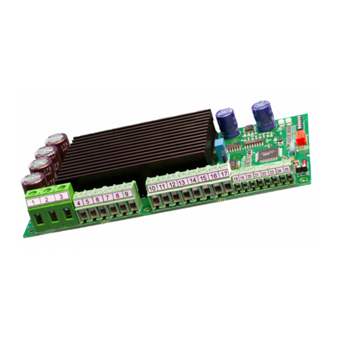
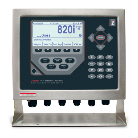
H.E. Anderson Ratio Feeder J+ Advanced Series User manual

Ratio Feeder®
Series J+ Advanced Pumper Controller
GETTING TECHNICAL ASSISTANCE
The H.E. Anderson Company is dedicated to assisting our customers ith installation and use of our
products. Our technical staff are available each eekday from 8:30am to 4:30pm central time. You may
call us toll free at 1-800-331-9620 from any here in the U.S.A.. and Canada. If no one is available, e
ill promptly return your call.
Be ore you call, e suggest that you revie this manual. You may find the ans er to your question here.
But even if you do not, revie ing the manual ill help us to help you.
There is some in ormation you should have available hen you call. You should kno the soft are
version and serial number of your control unit. Also, you should note the number of pumpers of each type,
and their model numbers. We may not need all this information, but having it available at the start can
some times save a lot of time and trouble for you. You may record the information on the information page
belo for convenient reference.
If you need an additional o ners manual for any H.E. Anderson Company product, please visit our
ebsite at http://heanderson.com/manuals.php
UNPACKING
Please open and inspect
your package upon receipt.
Your package as packed
ith great care and all the
necessary packing materials
to arrive to you undamaged.
If you do find an item that is
broken or damaged, you
must contact the delivering
carrier to report the claim.
Figure 1
J Plus Controller

J+ Advanced In ormation Summary
Summary of installation steps:
1. Decide here to place all system components. Consult component specific HEA manuals for individual
components (J Controller, Water Meter, Manifold, Pump Heads Blend Tank).
2. Install and leak check all plumbing including the manifold supply, ater meter, injection point fittings
and blend tank.
3. Install the manifold and pump heads.
4. Mount controller and make connections bet een the controller, ater meter and manifold(s).
5. Po er on and configure J controller.
This manual covers steps 4 and 5 and assumes steps 1-3 are complete. Consult the J Series Installation
Guidelines (http:// .heanderson.com/Install-Guidelines.pdf) and individual component manuals for prior
steps.
Do all iring before connecting po er. Use a surge suppressor on the incoming AC po er line. Plug in the
po er cord and atch the LCD display. If it does not come on, unplug the po er and check the iring.
This unit as ordered ith the follo ing capacities or settings:
MODEL NO. _____________ SERIAL NO. ______________
Customer Requested _____ Default _____
Soft are Version ____________
K Factor [Pulses per Gallon]____________
Maximum Flo ____________
Pumper Models:
PUMPER #1________
PUMPER #2________
PUMPER #3________
PUMPER #4________
PUMPER #5________
PUMPER #6________
PUMPER #7________
PUMPER #8________
GPS=Gallons Per Stroke
GPS #1________
GPS #2________
GPS #3________
GPS #4________
GPS #5________
GPS #6________
GPS #7________
GPS #8________
Once settings have been properly entered into the controller, the ratios for each output can be vie ed
on the controller’s display. To manually calculate the injection ratio for each pumper use the formulas
belo . With the above settings, pumpers ill have the follo ing chemical to ater feed ratio capacities (At
dial setting 10).
BASE #1 = (GPS #1 x N) ÷ 80 = _______ N=3785(gal.)
H8 1:______ (BASE #1) H4, P4 1:______ (BASE #1 x 2)
H2, P2 1:______ (BASE #1 x 4) H1, P1, A10 1:______ (BASE #1 x 8)
A3 1:______ (BASE #1 x 26.7)
BASE #2 = (GPS #2 x N) ÷ 80 = _______
H8 1:______ (BASE #1) H4, P4 1:______ (BASE #1 x 2)
H2, P2 1:______ (BASE #1 x 4) H1, P1, A10 1:______ (BASE #1 x 8)
A3 1:______ (BASE #1 x 26.7)
BASE #3 = (GPS #3 x N) ÷ 80 = _______
H8 1:______ (BASE #1) H4, P4 1:______ (BASE #1 x 2)
H2, P2 1:______ (BASE #1 x 4) H1, P1, A10 1:______ (BASE #1 x 8)
A3 1:______ (BASE #1 x 26.7)
BASE #4 = (GPS #4 x N) ÷ 80 = _______
H8 1:______ (BASE #1) H4, P4 1:______ (BASE #1 x 2)
H2, P2 1:______ (BASE #1 x 4) H1, P1, A10 1:______ (BASE #1 x 8)
A3 1:______ (BASE #1 x 26.7)
If more than one pumper is used to pump the same chemical, divide the ratio (BASE) by the number
of pumpers used for that chemical. The J+ Advanced can operate up to 8 manifolds. Repeat the above
formulas for BASE #5,6,7 and 8 if in use.

Mounting
Ensure the installation location has all the follo ing:
●Allo easy access to front panel
●Must have access to 120 VAC po er outlet.
●Close proximity to other injector components.
●Protect from direct spray
Mount the controller using the 4 metal tabs on the back of the controller enclosure.
Electrical Connections
Legend:
1. External communication connector (see modbus manual)
2. Water meter connector
3. Output connector (1 through 8)
4. Ground connectors
5. Output Type Selector (Jumper 2-9) CAN DAMAGE EQUIPMENT IF SET INCORRECTLY
6. Flo meter Voltage (Jumper 1) DO NOT ADJUST WITHOUT CONSULTING FACTORY
7. Modbus Terminator (Jumper 10) (see modbus manual)
8. Po er connector
Complete the follo ing steps to connect the control box to the required components:
1. Ensure the J+ Advanced controller is NOT connected to electricity.
2. Open the enclosure by releasing the t o latched on the right side of the controller.
Illustration 1: Output Board

WARNING! Connecting the flow sensor incorrectly can damage the flow sensor
electronics.
3. Connect the ater meter by running the ater meter cable through the proper strain relief
connector. The terminals on the flo sensor terminal block are labeled 1, 2, & 3, both on the
terminal board and on the sensor cable. Match the ‘1’, ‘2’ and ‘3’ on the cable to the
corresponding numbers on the terminal marked ‘FLOW’ inside the box. Use a small scre driver
to tighten the connections on the terminal block. If you need a longer cable, use the color coding
to be sure that these connections are correct.
4. The valve output cables should already be connected to the output terminals. If they are not or
more output cables are being added, feed the cables through the appropriate strain relief bushing
on the bottom of the box, then connect the ires up to the proper output terminal number.
◦For Anderson Pilot Valve Manifolds, match the ‘1’, ‘2’ and ‘3’ on the output cable to the
corresponding numbers on the connector.
◦For Solenoid Pumps, match the ‘2’ on the solenoid pump cable to the ‘2’ on the output
terminal block and connect the ire labeled ‘GND’ to one of the 3 positions on the ‘GND’
terminal block. Refer to Illustration 3 for more information.
◦For existing Anderson pilot valve output cables ith only 2 conductors, connect one ire to
position 1 of an output connector and connect the other ire to position 2 of the same output
connector. The order does not matter.
Note: The J+ Advanced controller is only compatible ith 12VDC coils on pilot valves and
manifolds. If the J+ Advanced is being used ith an existing pilot valve or manifold, ensure
the coil is 12VDC or purchase a 12VDC coil (Part #18332) to convert the pilot valve.
Illustration 2: Entrance Connectors

WARNING! Incorrect jumper settings can damage the damage the connected pump
or valve.
5. Each output can be set using the jumpers to control either a traditional Anderson manifold pilot
valve or a solenoid pump.
◦Upper position for Anderson Pilot Valve Manifolds
◦Lo er position for Solenoid Pumps
Ensure the jumper positions are set properly. Check each output jumper to make sure the
position matches the type of device connected to the output.
Illustration 3: Wire Connections
Illustration 4: Jumper Positions

Powering Up The Unit
Plug the controller A surge suppressor/uninterrupted po er supply should be used to po er the controller.
When po er is applied to the unit, the display ill flash and then it ill display:
“Anderson Injectors
J+ Advanced
Version Number
Date”
for a short time as it initializes and ill then start displaying the flo (or OFF if there is no flo , or meter
connected to it), maximum theoretical flo limit for the current settings, and the gallons totalizer value. If
the above message is not displayed then unplug the box immediately and consult the factory for further
instructions.
Setting Up the Controller
The controller must be configured in order to ork properly. Controllers ordered ith a
meter from the factory should be properly configured on delivery. Ho ever, settings should
be double checked for correct configuration.
Make sure the follo ing parameters have been programmed correctly into the controller:
•k Factor
•Active manifolds (outputs)
•Gallons per Stroke for each outputs
•Output mode for each output
•Feed is enabled for each output
Re er to the included quick start guide below to con irm and change controller
settings.

J+ Advanced Start-Up Guide (Version J8A 3.4, 04/01/1 and later)
Page 1
This guide will lead you through the menus used to display and set system parameters.
If you have ordered your J+ Advanced controller as part of a system which includes a water meter, one or more
manifolds, or solenoid pumps, some of the parameters may already be properly set.
ou can use the ▼ and ▲ keys to navigate the top level menus in normal or reverse order. After a 10 second
period with no key press the display will return to the base display. During this period you can move forward or
reverse through the menu sequence. Pressing the Cancel/Exit key will return to the base display immediately.
Any top level menu item with 'Q' characters at the margins allows operator to press Enter to enter or change a
value or perform the currently displayed function. Pressing Cancel/Exit will exit the screen will return to the base
display.
All numeric entries are right justified as they are entered. Decimal places are fixed, and when entering values
with decimal positions, trailing zeros must be entered.
Numeric values are for illustrative purposes only
Base (default) display and top level menu rotation
The Base Display shows the
instantaneous flow,
maximum flow for full
capacity chemical feed, and
the resettable totalizer.
Additional information and
warning messages may be
displayed on line 4. See
Warning, Error, &
Information Messages
(Display Line 4), Page 4
There are both a resettable and
a non-resettable totalizer.
Pressing Enter twice will
clear the resettable totalizer.
See Turning Individual
Manifold Feed n & ff,
Page 2
See Setting The VPS
(Flow Volume per
Stroke), Page 2
See TOTALIZERS, left
column.
See Priming a Pumper
(Pumphead) or
Solenoid Pump, Page 2
See System
Configuration Sub-
menu, Page 3
ou should have the
software version
number, and release
date handy when calling
the factory for assistance
See Turning Global
Chemical Feed n & ff,
Page 2

Selection Screen Pulsing ScreenPriming Screen
Only active outputs
are displayed Pulse CountPulse Indicator
Enter
Exit
Enter
Time-out
or Exit
Priming sends a sequence of six (6) pulses to the selected manifold. If you have more than one pumper on a
manifold and you do not want to prime them all, you will need to turn off some pumpers with the shut-off valves
located on the manifold. Cancel/Exit will abort the priming sequence after the current stroke. There is a thirty
second period before the controller returns to the base display. During that period you may press Enter to repeat
the sequence or you can press Cancel/Exit to return to the selection screen and select another output.
Priming a Pumper (Pumphead) or Solenoid Pump
J Plus Advanced Start-Up Guide
Page 2
Turning Global Chemical Feed n or ff
Enter switches to alternate state:
FEED IS ON to FEED IS OFF
or FEED IS OFF to FEED IS ON
Cancel
Enter
Exit
Loop until all
active outputs
have been set.
Enter
Enter
Turning Individual Manifold Feed n or ff
Enter Enter
Exit
Enter switches to alternate state:
FEED IS ON (FEEDING) to FEED IS OFF (PAUSED)
or FEED IS OFF (PAUSED) to FEED IS ON (FEEDING)
Loop until all
active outputs
have been set.
Enter
Exit
Setting The VPS (Flow Volume per Stroke)
The VPS (Volume Per Stroke) will be displayed as either
Gallons per Stroke or Liters per Stroke according to the setting of
the K Factor Unit (See Page 3)
Both decimal places must be entered, even if zero.
Cancel
Enter Set Value
Enter
If the manifold capacity has been
entered the stroke capacity and
feed ratio at the current setting will
be displayed. Otherwise the line
will show “Capacity Not efined”

J Plus Advanced Start-Up Guide
Configuration Sub-menu
Page 3
Configuration Sub-menu
Top Level Menu, Page1
Enter
This setting is used only when remotely communicating with the controller over a
Modbus link (RTU mode). Otherwise it can be ignored. The The device operates as a
slave. Communications are via RS-485 serial connection operating at 9600 baud. See
the Modbus Addendum for the register description.
ou may enter an optional 4-digit numeric security code to prevent unauthorized access. If
you enter a code, Access beyond the TOTALIZERS display is denied without entering the
security code. Once the screen reverts to the base (default) display the code will have to be
reentered. To set, change, or clear the security code, press Enter and follow the prompts.
Entering ‘0000’ for the code will clear the code and turn off security.
The K Factor value is critical to accurate operation of the system. The K Factor is usually
shown somewhere on the water meter. Enter the K Factor (Pulses Per Gallon/Liter) value.
If you are using fewer than eight outputs setting this value to the maximum number used will
speed navigation through the MANIFOLDS ON/OFF and MANIFOLD RATES screens.
Enter
Enter
Cancel
Set Value
See Setting the Pump
Type and Stroke Capacity
for Each utput, Page 4
The K Factor Unit determines what volume unit (gallons or liters) is used for flow rate
display, totalization, and the Volume per Stroke setting. Changing the unit will clear
both the resettable and grand totals and cannot be undone.
Enter
Exit
Enter
Exit
Exit
Cancel
Enter Set Value
Enter
Enter Set Value
Enter
Cancel

Page 4
To configure a manifold is a two step process. ou must first set the pump type and then enter the chemical capacity per
stroke. Each output must be selected and configured separately.
1) Press Enter to choose the output number to configure.
2) Follow the screen instructions to set the pump type and Press Enter to set and display the Capacity per Stroke.
3) Press Enter again to set the stroke capacity using the numeric keypad. ou must enter the decimal place, even
if zero. This capacity should be the total combined capacity of all pumpers attached to that output which are pumping
a single chemical and for which you want to display the combined feed ratio when setting the VPS.
4) After setting the values you will be returned to the Output selection screen where you can configure another output.
J Plus Advanced Start-Up Guide
HIGH FLOWS: 1 34
The “HIGH FLOWS” line is shown only when the flow exceeds the Max. Flow shown in line 2. The “Max. Flow” is the
computed flow at which the fastest (lowest VPS value) stroking manifold or Solenoid pump reaches its maximum stroking
rate. Each output has its own maximum flow, determined by its VPS setting. The lowest of these values is displayed on line
2. The output number of each output which exceeds its computed maximum is displayed on line 4. In the display above
outputs 1, 3, & 4 are affected. These outputs are being limited to their maximum stroking rate and therefore are pumping
less than their expected (set) feed rate.
MANIFOLDS UNDEFINED!
The message “MANIFOLDS UNDEFINED!” Is displayed when no manifolds are activated to pump. This occurs if no
outputs are turned or if the outputs which are turned on have a VPS setting of zero. Check the VPS settings (See Setting
The VPS (Flow Volume per Stroke), Page 2) of all attached manifolds and make sure all the manifolds you want to pump
are turned on. This message is not affected by flow.
The totalizer displayed here
is the resettable total.
Warning & Information Messages (Display Line 4)
Setting the Pump Type and Stroke Capacity for Each utput
Enter
Set Value
Enter
Cancel
Enter
Exit
Enter
Cancel
Enter
Exit
Set Type
Enter the value. The decimal must
be entered, even if zero.

Repair
efore opening the enclosure and doing anything inside you should remove ac
power from the unit.
The fuse is located on the DIN rail next to the po er supply, inside the plastic fuse holder.
Replace ith the same size and type.
Fuse Replacement
Other repairs are made by replacing complete circuit board assemblies. This should be done only by an
authorized repair person or under the direction of our technical staff.
Factory Service
Should you require service for your Ratio:Feeder® J+ Advanced controller or injector, the H.E. Anderson
Co. offers several flexible factory service options. Call our number listed in the front of this manual for
complete information. If you need to return any parts for service or replacement, our shipping address is:
H.E. Anderson Company
2100 Anderson Drive
Muskogee, Oklahoma 74403
USA
Please enclose a note detailing the problems and the type of service you need. Include the name of a
contact person, phone number, and the billing name and address. Any return for arranty, or credit, must
have an RMA number. Contact H.E. Anderson for this number before returning.
Speci ications
Power Requirements
120 VAC Standard
Enclosure
Gasket sealed plastic enclosure ith sealed front panel.
Display
20 character x 4 line LCD
Flow Totalizer
0 – 99,999,999 gallons
Flow Meters
Multi-Jet, Paddle heel, Turbine, or Custom type supplied by customer.
Outputs
8
Output Voltage
12 VDC for Anderson Pilot Valve Manifolds
5 VDC for solenoid pumps
Operating Temperature Range
33 – 105°F
Table of contents
