MDT Technologies AKH-0400.01 User manual

MDT technologies GmbH • 51766 Engelskirchen • Papiermühle 1
12/2014
Technical Manual
MDT Heating actuators
AKH –0400.01
AKH –0800.01

Technichal Manual Heating Actuators AKH
MDT technologies GmbH • 51766 Engelskirchen • Papiermühle 1
2
1 Content
1 Content................................................................................................................................................. 2
2 Overview............................................................................................................................................... 4
2.1 Overview devices........................................................................................................................... 4
2.2 Usage & Areas of use..................................................................................................................... 4
2.3 Exemplary circuit diagram............................................................................................................. 5
2.4 Structure & Handling..................................................................................................................... 6
2.5 Functions ....................................................................................................................................... 7
2.5.1 Overview Functions................................................................................................................ 8
2.6 Channel-LEDs................................................................................................................................. 9
2.7. Settings at the ETS-Software ........................................................................................................ 9
2.8. Starting up .................................................................................................................................... 9
3 Communication objects...................................................................................................................... 10
3.1 Overview...................................................................................................................................... 10
3.2 Global Communication objects ................................................................................................... 10
3.3.1 Communication objects –switching (1 Bit).......................................................................... 11
3.3.2 Communication objects –continuous (1 Byte) .................................................................... 11
3.3.3 Communication objects –integrated controller .................................................................. 12
3.4 Default settings of the communication objects .......................................................................... 14
4 Reference ETS-Parameter .................................................................................................................. 16
4.1 Setup general............................................................................................................................... 16
4.1.1 Device configuration ............................................................................................................ 16
4.1.2 Summer/Winter mode ......................................................................................................... 17
4.1.3 Heating/Cooling requirement & switchover ........................................................................ 18
4.1.4 Protection of forse fit ........................................................................................................... 19
4.1.5 Max. Control value ............................................................................................................... 20
4.1.6 Behavior after bus power reset............................................................................................ 21
4.2 Mode selection............................................................................................................................ 22
4.3 Channel Configuration –sithig Bit................................................................................ 23
4.3.1 General setting ..................................................................................................................... 23
4.3.2 Blocking function.................................................................................................................. 25
4.3.3 Emergency mode.................................................................................................................. 25
4.3.4 Forced position/Dew point alarm ........................................................................................ 26
Technichal Manual Heating Actuators AKH
MDT technologies GmbH • 51766 Engelskirchen • Papiermühle 1
3
4.4 Channel Configuration –otiuous Bte.......................................................................... 28
4.4.1 PWM cycletime..................................................................................................................... 29
4.4.2 Limitation of the control value............................................................................................. 32
4.4.3 Flow temperature limit ........................................................................................................ 33
4.5 Channel Configuration –itegated otolle........................................................................ 34
4.5.1 Operating modes.................................................................................................................. 36
4.5.2 Priority of the operating modes ........................................................................................... 38
4.5.3 Operating mode switchover................................................................................................. 38
4.5.4 Setpoint offset...................................................................................................................... 41
4.5.5 Message function ................................................................................................................. 43
4.5.6 Heating/Cooling system ....................................................................................................... 44
4.5.7 Additional settings at combined heating & cooling mode................................................... 46
5 Index ................................................................................................................................................... 47
5.1 Register of Illustrations ............................................................................................................... 47
5.2 List of tables................................................................................................................................. 48
6 Attachment......................................................................................................................................... 50
6.1 Statutory requirements............................................................................................................... 50
6.2 Routine disposal .......................................................................................................................... 50
6.3 Assemblage.................................................................................................................................. 50
6.4 Controller..................................................................................................................................... 51
6.4.1 2-Step control....................................................................................................................... 51
6.4.2 PI-control continuous ........................................................................................................... 52
6.4.3 PI-control switching (PWM) ................................................................................................. 53
6.5 Direction of controller ................................................................................................................. 54
6.5 Datasheet .................................................................................................................................... 54

Technichal Manual Heating Actuators AKH
MDT technologies GmbH • 51766 Engelskirchen • Papiermühle 1
4
2 Overview
2.1 Overview devices
The manual refers to the following devices (Order number respectively written in bold letters):
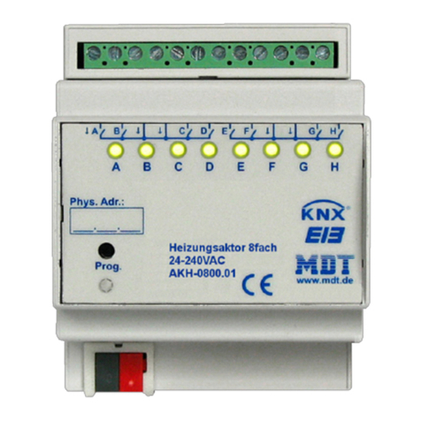
AKH-0400.01 Heating actuator 4-fold, 2TE, 24 or 230V AC, MRDC
o4 channels for electrothermic valve drives, for the maximum number of
electrothermic valve drives have a look at 6.5 Datasheet, detection of 230V AC
failure, 230V AC/24V AC short circuit detection of connected load
AKH-0800.01 Heating actuator 8-fold, 2TE, 24 or 230V AC, MRDC
o8 channels for electrothermic valve drives, for the maximum number of
electrothermic valve drives have a look at 6.5 Datasheet, detection of 230V AC
failure, 230V AC/24V AC short circuit detection of connected load
Attention: Every actuator can be connected to 230V AC or 24V AC.
A mixture of both voltages forbidden!
2.2 Usage & Areas of use
The heating actuator can be connected to 24V AC or 230V AC, so it allows controlling electrothermic
valve drives with 24V AC or 230V AC. The heating actuator is available at the design of 4-fold or 8-
fold.
Integrated 230V AC failure detection as well as short circuit detection, for both voltage types, at the
load allows a high fail-safety. Additional an emergency mode can be adjusted, which gets active
when the cyclic control value fails.
The actuator can be controlled as well by a 1 Bit object as by a 1 Byte object. As special feature, the
controller contains of an integrated controller, which allows controlling the actuator directly by a
temperature value. The integrated controller contains of the 4 operating modes, comfort, night,
standby, and frost-/heat protection. The setpoints can be adjusted individual for the single operating
modes as well as for the heating and cooling mode.
A limitation of the control value, summer /winter mode as well as a protection of the valves
completes the range of service of the heating actuator.

Technichal Manual Heating Actuators AKH
MDT technologies GmbH • 51766 Engelskirchen • Papiermühle 1
5
2.3 Exemplary circuit diagram
Figure 1: Exemplary circuit diagram heating actuator 4-fold 230V
Figure 2: Exemplary circuit diagram heating actuator 4-fold 230V

Technichal Manual Heating Actuators AKH
MDT technologies GmbH • 51766 Engelskirchen • Papiermühle 1
6
2.4 Structure & Handling
The heating actuator, here a 4-fold actuator is shown, contains of the standard elements
programming-knob, programming-LED, which shows an active programming mode, and a bus-
connection.
The electrothermic valve drives can be connected by the terminal strip with respecting the circuit
diagrams.
Every single channel contains of a status-LED, which shows an active channel by a slow flashing. The
ratio of on to off corresponds the current control value. A significant faster flashing of the LEDs
shows an active disturbance of this channel.
Figure 3: Overview hardware module

Technichal Manual Heating Actuators AKH
MDT technologies GmbH • 51766 Engelskirchen • Papiermühle 1
7
2.5 Functions
The functions are identical for all channels. According to the hardware specification, the device
contains of up to 8 channels-
The labeling of the channels is in alphabetically consecutive order.
The general settings are the same for all of the channels.
There are 4 possible functions for each channel:
Channel
The channel has no function. So there are not any parameterization options for this channel.
switching (1 Bit)
The channel works with a 1 Bit value for the control value, e.g. from a two-step controller or
a PWM-signal. So the output can only be switched on or off at a change of the 1 Bit Input
signal.
By further options like valve type, activatable blocking objects, activatable emergency mode
and dew point alarm as well as status objects, the channel can be adjusted for the present
valve type.
continuous (1 Byte)
The channel works with 1 Byte value for the control value, e.g. from a PI-controller. The Input
signal is transmitted to the valve by a PWM-controller with adjustable cycle time.
Next to the same parameterization options like the 1 Bit input value, the actuator contains of
limitations for the control value and the flow temperature at the 1 Byte mode.
integrated controller
When a channel is selected as integrated controller, the channel creates an own continuous
control value from an existing temperature value. This continuous control transmitted to the
switching output by a PWM-signal.
Next to the same parameterization options as by the 1 Byte input value, the actuator
contains of a lot additional settings for the controller at the integrated controller mode.

Technichal Manual Heating Actuators AKH
MDT technologies GmbH • 51766 Engelskirchen • Papiermühle 1
8
2.5.1 Overview Functions
General settings
Settings
Startup delaytime
Selection of 24V AC or 230V AC mode
Objects for requirement Heating/Cooling
activatable
Adjustment of heating/colling switchover
Protection of forse fit activatable
Behavior after bus power reset
Summer/Winter mode adjustable
Channel selections
switching (1Bit)
continous (1Byte)
integrated controller
switching (1 Bit)
Switching functions
Valve type adjustable
Blocking objects activatable
Adjustable emergency mode
Forced position/dew point alarm adjustable
Status objects for the control value activatbale
continuous (1 Byte)
Switching functions
same as switching-mode (1Bit)
Control value functions
PWM-cycle time parameterize able
Minimum & Maximum limitation of the
control value at heating parameterize able
Minimum & Maximum limitation of the
control value at cooling parameterize able
Flow temperature limit
(additional temperature sensor at the flow
requested)
integrated
controller
Switching functions
same as switching-mode (1Bit)
Control value functions
same as continuous-mode (1Byte)
Controller functions
System (2 Pipe/4 Pipe) adjustable
4 modes individual parameterize able
Priority of the modes adjustable
Switchover of the mode by Bit or Byte object
available
Setpoint shift parameterize able
Message for exceeded/underflow of
adjustable temperature available
Heating-/Cooling system by control
parameters adjustable
Table 1: Overview functions

Technichal Manual Heating Actuators AKH
MDT technologies GmbH • 51766 Engelskirchen • Papiermühle 1
9
2.6 Channel-LEDs
Every channel contains of a LED, which shows the current state of the channel. Additional to the
status, these LEDs show errors of the channels.
The errors are shown as described below:
only one of the channel-LEDs flashes 7 fast flashig, short rak, 7 fast flashig, …
The belonging channel is at the overload mode or has a short circuit at the output.
At the 230V mode a mains voltage failure can additional be recognized. Because often 4
channels are supplied in common, all 4 channels are flashing.
all channel-LEDs flashing
At the four fold actuator, the first channel must be always connected to a load. At the 8-fold
actuator, additional the fifth channel must be connected to a load. Otherwise the actuator
will switch to the error mode and show this by a flashing off all channel-LEDs.
The normal behavior of the actuator is also shown via these LEDs as described below:
switching mode (1 Bit)
The LED shows the switching behavior of the output. If the 2-step controller sends a 1-signal,
the LED is switched on.
continuous mode (1 Byte)/ integrated controller
The LED operates at the PWM mode with the fixed period of 4s and flashes with the cadence
of the control value. At a control value of 50%, the LED will shine for 2s and will be off for 2s.
2.7. Settings at the ETS-Software
Auswahl in der Produktdatenbank
Manufacturer: MDT Technologies
Product family: Actuator
Product type: Heating Actuators
Medium Type: Twisted Pair (TP)
Product name: addicted to the used type, e.g.: AKH-0800.01 Heating actuator 8-fold, 4TE
Order number: addicted to the used type, e.g.: AKH-0800.01
2.8. Starting up
After wiring, the allocation of the physical address and the parameterization of every channel follow:
(1) Connect the interface with the bus, e.g. MDT USB interface
(2) Set bus power up
(3) Press the programming button at the device(red programming LED lights)
(4) Loading of the physical address out of the ETS-Software by using the interface(red LED goes
out, as well this process was completed successful)
(5) Loading of the application, with requested parameterization
(6) Switch the power supply on
(7) If the device is enabled you can test the requested functions(also possible by using the ETS-
Software)

Technichal Manual Heating Actuators AKH
MDT technologies GmbH • 51766 Engelskirchen • Papiermühle 1
10
3 Communication objects
3.1 Overview
The communication objects are for programming the actuator. The assignment can be done by these
objects.
For every channel, 20 objects are reserved. The communication objects for the single channels have
only influence to the belonging channels. The numbering of the communication objects is standardly
done this way, also if not all of the 20 objects are used or a channel is completely deactivated. So the
channel A has the objects from 0 to 19, the channel B from 20 to 39 and so on.
After the objects for the single channels, the global valid objects are following. These objects can
have influence to all channels. At the 4-fold actuator, these objects start with number 80 and at the
8-fold actuator with the number 160.
3.2 Global Communication objects
The global communication objects are following to the objects of the single channels. According to
the parameterization maximum 6 global objects can be shown. The first two objects, numbers
80/160 and 81/161, are for the switchover of summer/winter mode and for the switchover of
heating/cooling. The two following objects are state objects of the size of 1 Bit. The object 82 sends a
1, if at least one channel is active. The object 83/163 reports an error. The last two objects have the
size of 1 Byte and are for the shifting of the maximum control value or the responding of the current
value. The maximum control value can be adjusted by object 85165; the object 84/164 sends the
current maximum.
The following illustration shows the global communication objects:
Figure 4: global Communication objects (AKH-0800.01)
Die nachfolgende Tabelle zeigt die 6 globalen Kommunikationsobjekte:
Nr.
Function
Usage
80/160
Summer/Winter
Switchover
In, Write
81/161
Heating/Cooling
Switchover
In, Write
82/162
Heating/Cooling
requirement
Status Heating/Colling mode
In, Read
83/163
Fault
Display of power failure/short circuit
Out, Read
84/164
Max. control value
Status of the current maximum control
value
Out, Read
85/165
Max. control value
Adjustment of the maximum control value
Out, Write
Table 2: global Communication objects

Technichal Manual Heating Actuators AKH
MDT technologies GmbH • 51766 Engelskirchen • Papiermühle 1
11
3.3 Communication Objects per Channel
According to the setting, different objects are shown for this channel. The following sections show
the communication objects for each state. The numbers of the communication objects are always
shown for channel A. At channel B, the numbers would be increased by 20, at channel C by 40 and so
on.
3.3.1 Communication objects –switching (1 Bit)
If a hael is seleted as „sithig Bit, the folloig ojets, depedig to the
parameterization, will be shown:
Figure 5: Couiatio ojets „sithig 1Bit
The control value is executed as 1 Bit value. Furthermore additional objects, depending to the
parameterization, are available.
The chart shows the available objects:
Nr.
Function
Usage
0
Control Value
Input for external control value
In, Write
2
Block
blocks the channel
In, Write
3
State control value
sends the current value of the control
value
Out, Read
4
Message emergency
mode
indicates an active emergency mode
Out, Read
5
Forced position
activates the forced position
In, Write
5
Dew point alarm
activates the dew point alarm
In, Write
Table 3: Couiatio ojets „sithig1Bit
3.3.2 Communication objects –continuous (1 Byte)
If a hael is seleted as „otiuous Bte , the folloig ojets, depedig to the
parameterization, are shown:
Figure 6: Couiatio ojets „otiuous 1Bte
The control value is executed as 1 Byte value. Furthermore additional objects, depending to the
parameterization, are available.

Technichal Manual Heating Actuators AKH
MDT technologies GmbH • 51766 Engelskirchen • Papiermühle 1
12
The chart shows the available objects:
Nr.
Function
Usage
0
Control value
Input for external control value
In, Write
1
Flow temperature
Adjustment of the limitation of the
flow temperature
In, Write
2
Block
blocks the channel
In, Write
3
State control value
sends the current value of the control
value
Out, Read
4
Message emergency
mode
indicates an active emergency mode
Out, Read
5
Forced position
activates the forced position
In, Write
5
Dew point alarm
activates the dew point alarm
In, Write
Table 4: Couiatio ojets „otiuous1Bte
3.3.3 Communication objects –integrated controller
If a channel is selected as integrated controller, the following objects, depending to the
parameterization, will be shown:
Figure 7: Couiatio ojets „itegrated otroller
Because of the control value is created by the integrated controller itself, no object for the control
value is shown. Instead of this, an object for the temperature measurement (Input) is shown.

Technichal Manual Heating Actuators AKH
MDT technologies GmbH • 51766 Engelskirchen • Papiermühle 1
13
The chart shows the available objects:
Nr.
Function
Usage
0
Temperature Value
Input for external temperature value
In, Write
1
Flow temperature
Input for external temperature signal
of the flow temperature
In, Write
2
Block
blocks the channel
In, Write
3
State control value
sends the actual control value
Out, Read
4
Message emergency mode
indicates active emergency mode
Out, Read
5
Forced position
activates the forced position
In, Write
5
Dew point alarm
activates the dew point alarm
In, Write
6
PWM-Cooling for 4 Pipe
system
Output for Cooling at a divided
heating/cooling system
Out, Read
7
Setpoint comfort
adjustment of a new absolute
setpoint
In, Write
8
Setpoint value offset
Shifting of the actual setpoint
In, Write
9
Actual setpoint
Sending of the actual control value
Out, Read
10
Mode selection
Adjustment of the operating mode
In, Write
11
DPT_HVAC Status
sends feedback of the current
operating mode
Out, Read
12
DPT_RHCC Status
sends feedback of the current
operating mode
Out, Read
13
Mode comfort
switches mode comfort
In, Write
14
Mode night
switches mode night
In, Write
15
Mode frost/heat
protection
switches mode frost/heat protection
In, Write
16
Frost alarm
reports an active frost alarm
Out, Read
17
Heat alarm
reports an active heat alarm
Out, Read
Table 5: Communication objects integrated controller

Technichal Manual Heating Actuators AKH
MDT technologies GmbH • 51766 Engelskirchen • Papiermühle 1
14
3.4 Default settings of the communication objects
The following chart shows the default settings of the communication objects:
Default settings
Nr.
Name
Object Function
Length
Priority
C
R
W
T
U
0
Channel A
Control value
1 Bit
Low
X
X
X
0
Channel A
Control value
1 Byte
Low
X
X
X
0
Channel A
Temperature value
2 Byte
Low
X
X
X
1
Channel A
Flow temperature
2 Byte
Low
X
X
2
Channel A
Block
1 Bit
Low
X
X
3
Channel A
State control value
1 Bit
Low
X
X
X
3
Channel A
State control value
1 Byte
Low
X
X
X
4
Channel A
Message emergency mode
1 Bit
Low
X
X
X
5
Channel A
Forced position
1 Bit
Low
X
X
5
Channel A
Dew point alarm
1 Bit
Low
X
X
6
Channel A
PWM-Cooling for 4 Pipe
system
1 Byte
Low
X
X
X
7
Channel A
Setpoint comfort
2 Byte
Low
X
X
8
Channel A
Setpoint value offset
2 Byte
Low
X
X
9
Channel A
Actual setpoint
2 Byte
Low
X
X
X
10
Channel A
Mode selection
1 Byte
Low
X
X
X
11
Channel A
DPT_HVAC Status
1 Byte
Low
X
X
X
12
Channel A
DPT_RHCC Status
2 Byte
Low
X
X
X
13
Channel A
Mode comfort
1 Bit
Low
X
X
X
14
Channel A
Mode night
1 Bit
Low
X
X
X
15
Channel A
Mode frost/heat protection
1 Bit
Low
X
X
X
16
Channel A
Frost alarm
1 Bit
Low
X
X
X
17
Channel A
Heat alarm
1 Bit
Low
X
X
X
+20
next Channel
80/160
Summer/Winter
Switchover
1 Bit
Low
X
X
X
81/161
Heating/Cooling
Switchover
1 Bit
High
X
X
X
82/162
Heating/Cooling
requirement
0 if all valves closed, else 1
1 Bit
High
X
X
X
83/163
Fault
At power failure/short circuit
1 Bit
High
X
X
X
84/164
Max. control value
Output
1 Byte
High
X
X
X
85/165
Max. control value
Input
1 Byte
High
X
X
Table 6: Default-settings of the communication objects

Technichal Manual Heating Actuators AKH
MDT technologies GmbH • 51766 Engelskirchen • Papiermühle 1
15
You can see the default values for the communication objects from the upper chart. According to
requirements the priority of the particular communication objects as well as the flags can be
adjusted by the user. The flags allocates the function of the objects in the programming thereby
stands C for communication, R for Read, W for write, T for transmit and U for update.

Technichal Manual Heating Actuators AKH
MDT technologies GmbH • 51766 Engelskirchen • Papiermühle 1
16
4 Reference ETS-Parameter
4.1 Setup general
The general settings are shown at the illustration below. These settings are valid for all channels:
Figure 8: Setup general
4.1.1 Device configuration
The following both parameters are for the configuration of the actuator:
Figure 9: Device configuration
The following chart shows the dynamic range of this parameter:
Sub function
Dynamic range
[default value]
comment
Startup delaytime
0-60s
[0s]
Time, which elapses between bus
power reset and the restart of the
device
Thermal driving
24V
230V
Adjustment of the voltage level at
the thermal drivings
Table 7: Device configuration

Technichal Manual Heating Actuators AKH
MDT technologies GmbH • 51766 Engelskirchen • Papiermühle 1
17
The startup delay time defines the time, which elapses between a bus power return or an ETS-
Download and the functional restart of the device.
The setting of the voltage level defines the voltage for the connected thermal drives. This setting
changes only the fault detection, other functions are identical. At the 230V mode, the fault detection
recognizes power failure as well as short circuits. At the 24V mode only short circuits are recognized.
If a fault is detected, a 1-signal is sent by the belonging communication object. Additional, the
channel, which is in the fault mode, reacts with a fast flashing of the belonging channel LED. If the
230V main voltage failures, all 4 channels flash, which are connected to this L-connection.
Number
Name
Length
Usage
83/163
Fault
1 Bit
reports an active fault
Table 8: Communication object fault
Attention: The first channel of the 4-fold actuator as well as the first and fifth channel of
the 8-fold actuator has to be connected first. Otherwise a fault will be detected!
Attention: Every actuator can operate only one voltage, either 230V or 24V. A
combination of both voltages is forbidden because of the conductor track distances!
4.1.2 Summer/Winter mode
At the following settings, the summer/winter mode can be adjusted:
Figure 10: Summer/Winter mode
The following chart shows the dynamic range for this parameter:
Sub function
Dynamic range
[default value]
comment
Control values set to 0% at
summer mode
Yes
No
If this setting is active, the control
value will set to 0% at summer
mode
Polarity for object
Summer/Winter
Summer=1/Winter=0
Summer=0/Winter=1
Adjustment of the polarity for
switchover
Table 9: Summer/Winter mode
The heating actuator can be set in a summer or winter mode. The polarity of the switchover object
can be adjusted.
Additional a setting can be made which sets the control value continuous to 0% at the summer
mode. Of course, this setting can only be done if a switchover between heating and cooling is
disabled (have a look at 4.1.3). So the actuator works only at the heating mode.
Number
Name
Length
Usage
80/160
Summer/Winter
1 Bit
Switchover between summer and winter mode
Table 10: Communication object Summer/Winter mode

Technichal Manual Heating Actuators AKH
MDT technologies GmbH • 51766 Engelskirchen • Papiermühle 1
18
4.1.3 Heating/Cooling requirement & switchover
The switchover for heating and cooling defines whether the heating actuator shall switch a cooling or
not:
Figure 11: Heating/Cooling switchover
The following chart shows the dynamic range for this parameter:
Sub function
Dynamic range
[default value]
comment
Object for requirement
Heating/Cooling
not active
send 1 if required
send 0 if required
send 1 if required, 20
min power off delay
send 0 if required, 20
min power off delay
Activation of the object
heating/cooling requirement and
adjustment of the signal for
requirement
Switching for cooling
not active
via object
summer/winter
via object cooling
Adjustment whether the actuator
shall switch a cooling or not;
defines the switchover between
heating and cooling.
Control values set to 0% at
summer mode
No
Yes
This setting can only be done if
the oolig is hose as ot
atie.
Table 11: Heating/Cooling switchover
The heating actuator can control as well heating-systems as cooling-systems and combined systems.
Adjustig the sithoe etee heatig ad oolig a e doe the paaete “ithig fo
oolig. This paaete defies hethe the sithoe shall e done via an own object or via the
ojet sue/ite. Fo eah hael a e adjusted idiiduall hethe it shall eat to the
switchover or not.
If the switchover is done by the object summer/winter, the actuator will switch automatically to
heating at the winter mode and to cooling at the summer mode. At the switchover via an own object,
the sithoe ill e doe ia the ojet heatig/oolig. A logial sithes the oolig o
ad a logial the heatig o.
The settig Cotol alues set to % at sue ode a ol e atiated if the heatig/oolig
switchover is disabled.

Technichal Manual Heating Actuators AKH
MDT technologies GmbH • 51766 Engelskirchen • Papiermühle 1
19
Via the paaete Ojet fo euieet Heatig/Coolig a e adjusted, hethe a additioal
object for the requirement of a heating or cooling process shall be shown. This object has its usage
e.g. at a pump control. If all valves are closed, for example the pump can be switched off to save
eeg. Via the settig sed if euied /sed if euied, the polait of this ojet a e
defined. The settig sed if euied effets, that the ojet seds a at a euieet ad a
he it is ot used. The additioal poe off dela peets the atuato off a to feuet
switching, e.g. at the PWM mode.
The following chart shows the belonging communication objects:
Number
Name
Length
Usage
81/161
Heating/Cooling
1 Bit
Switchover between heating(=1) and cooling(=0)
82/162
Heating/Cooling
requirement
1 Bit
sends a if all ales ae losed ad if one or
more are open
Table 12: Communication object Summer/Winter mode
4.1.4 Protection of forse fit
The following illustration shows the settings for this parameter:
Figure 12: Protection of forse fit
The following chart shows the dynamic range for this parameter:
Sub function
Dynamic range
[default value]
comment
Protection of forse fit (all 6 days
for 5min valve open/close)
inactive
active
activates the protection of forse
fit
Table 13: Protection of forse fit
To be sure, that a valves, which was not opened for a long period of time, does not block, the heating
actuator has a protection of forse fit. This protection controls all channels at a fixed period of 6 days
for 5 min and drives the valves once completely open.
So, a smooth operation of the valves can be secured.

Technichal Manual Heating Actuators AKH
MDT technologies GmbH • 51766 Engelskirchen • Papiermühle 1
20
4.1.5 Max. Control value
The following illustration shows the settings for this parameter:
Figure 13: max. Control value
The following chart shows the dynamic range for this parameter:
Sub function
Dynamic range
[default value]
comment
Object max. control value
inactive
send at changes
send at changes and at
cycle 30min
Activates the objects for the max.
control value and defines the
sending behavior of them
Table 14: max. Control value
The paaete Ojet a. otol alue defies hethe a ojet fo the aiu otol alue
shall be shown. If this parameter is activated with one of the two settings, two objects will be shown
which you can see at the chart below. The maximum control value is only sent at a change or at a
change and additional cyclically every 30min.
This function allows heatig’s, which can modulate their power, if only less power is required. The
object for the output (Number 84/164) sends the maximum used value at the heating actuator of the
enabled channels. Afterwards this output signal can be analyzed and send the used power to the
heating.
If more than one heating actuator is used, which get all their heating power from one heating, the
objects can be connected by the additional object of the input (Number 85/165). Therefore, the
output of the first actuator has to be connected to the input of the second actuator and so on. Now
the output object of the last actuator sends the maximum used power from all enabled channels of
the connected actuators.
Number
Name
Length
Usage
84/164
Max. control
value(Output)
1 Byte
sends the current maximum control value
85/165
Max. control value(Input)
1 Byte
receives the current maximum control value
from another actuator
Table 15: Communication objects max. Control value
Other manuals for AKH-0400.01
1
This manual suits for next models
1
Table of contents
Other MDT Technologies Controllers manuals

MDT Technologies
MDT Technologies AKU-0816.01 User manual

MDT Technologies
MDT Technologies SCN-RTRGW.02 User manual

MDT Technologies
MDT Technologies RF-TA55A2.01 User manual

MDT Technologies
MDT Technologies BE-GT2TW.01 User manual

MDT Technologies
MDT Technologies JAL-0206.01 User manual

MDT Technologies
MDT Technologies AKK UP Series User manual

MDT Technologies
MDT Technologies AKH-0400.01 User manual

MDT Technologies
MDT Technologies KNX SCN-LCDGW.01 User manual

MDT Technologies
MDT Technologies AMI-0416.03 User manual

MDT Technologies
MDT Technologies SCN-RT1UP.01 User manual