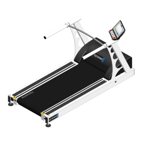
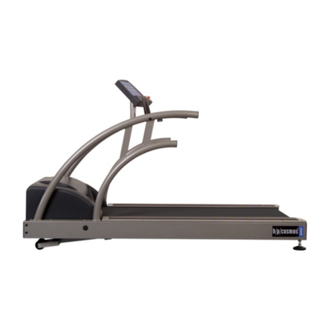
h/p/cosmos Arsalis Gaitway 3D User manual

gaitway-3D Service manual
Ref.:TM-MAN-0005-ARS Iss.: A Rev.: 9 Date: 07/12/2020 Page : I
gaitway-3D instrumentation
Service manual
gaitway-3D treadmill manufacturer:
h/p/cosmos: sports & medical gmbh
Am Sportplatz 8
DE 83365 Nussdorf-Traunstein
Germany
phone +49 86 69 86 42 0
fax +49 86 69 86 42 49
service@hpcosmos.com
www.hpcosmos.com
Version:
gaitway-3D treadmill firmware: MCU5-v1.08.3
MCU6-v1.2.0176
gaitway-3D Instrumentation manufacturer:
Arsalis SRL
Chemin du Moulin Delay, 6
B-1473 Glabais
Belgium
phone +32 10 474425
fax +32 10 473106
www.arsalis.com
Version:
gaitway-3D software: 1.6
gaitway-3D[Service] software: 1.6
gaitway-3D force amplifier firmware: 1.3

gaitway-3D Service manual
Ref.:TM-MAN-0005-ARS Iss.: A Rev.: 9 Date: 07/12/2020 Page : II
This service manual is only valid for the software / firmware version noted on the first
page of this manual and only for the original configuration of the first delivery of the
machine. Firmware updates, software updates, changes of the system configuration
or retrofitting of additional equipment or accessories can result in invalidity of this
manual. In case of alterations of the device or the additional equipment; the latest
version of the manual or the corresponding additional information always should be
considered.
The service manual for the gaitway-3D 150/50, gaitway-3D 170/65 and gaitway-3D
190/65 systems is split in two parts: the present manual covers all service instruction
and safety precautions for the instrumentation of the gaitway-3D instrumentation;
the service instructions and safety precaution for the gaitway-3D treadmill are
described in the instructions for use of the h/p/cosmos treadmill ergometer.
Throughout this manual, the sign below indicates instances where you should consult
the gaitway-3D treadmill service manual.
The present manual only covers the service relative to the gaitway-3D
instrumentation. More safety notes, warnings, precautions, service
instructions are available
in the instructions for use of the h/p/cosmos treadmill ergometer. Please
refer to the manual available at the address below:
https://www.hpcosmos.com/en/contact-support/media-downloads/manuals
All operations described in this manual, such as installation, commissioning, part
replacement and repair work, are to be carried out only by trained and authorized
technicians who have been certified by Arsalis. Customers must not perform these
kinds of tasks.
We recommend calling our competent service team or entering into a maintenance
contract for a routine service at an interval of 6 or 12 months for standard machines
and standard applications.
It is strictly forbidden to perform any amendments of the technical
design, technical specifications, labelling and configurations (except
allowed programming as described in this manual) of this machine
and the software and accessories connected to this machine.
Any amendments, unauthorized, poor or lack of service /
maintenance will result in loss of manufacturer’s liability and
warranty.

gaitway-3D Service manual
Ref.:TM-MAN-0005-ARS Iss.: A Rev.: 9 Date: 07/12/2020 Page : III
TABLE OF CONTENTS
1. Model overview.................................................................................................... 1
1.1. Options and accessories .............................................................................. 2
2. Introduction.......................................................................................................... 4
2.1. Description.................................................................................................... 4
2.2. Device components, including software and accessories............................. 4
2.2.1. Treadmill components........................................................................... 4
2.2.2. Treadmill supports................................................................................. 5
2.2.3. Force sensor units................................................................................. 6
2.2.4. Amplifier ................................................................................................ 6
2.2.5. gaitway-3D software.............................................................................. 7
2.3. Safety equipment.......................................................................................... 7
3. Safety notes, warnings, precautions.................................................................... 8
3.1. General......................................................................................................... 8
3.2. Room conditions and environmental requirements....................................... 8
3.3. Transport and installation ............................................................................. 9
3.4. Storage....................................................................................................... 10
3.5. Device care................................................................................................. 10
3.6. Service safety aspects................................................................................ 11
4. How to use this manual ..................................................................................... 11
5. Installation and commissioning.......................................................................... 11
5.1. gaitway-3D unpacking ................................................................................ 12
5.2. Treadmill support assembly........................................................................ 12
5.3. gaitway-3D floor fixation ............................................................................. 12
5.4. gaitway-3D final assembly.......................................................................... 14
5.5. gaitway-3D startup...................................................................................... 14
6. gaitway-3D sensors calibration.......................................................................... 14
7. gaitway-3D on-site check-out ............................................................................ 16
8. Amplifier replacement........................................................................................ 16
9. Load cell replacement........................................................................................ 16
10. Amplifier fuse replacement............................................................................. 16
11.Installation equipment.................................................................................... 17
12. Installation and commissioning checklist........................................................ 19
12.1. gaitway-3D unpacking............................................................................. 19
12.2. Treadmill support assembly.................................................................... 20
12.3. gaitway-3D floor fixation.......................................................................... 24
12.4. gaitway-3D final assembly ...................................................................... 27
12.5. gaitway-3D startup.................................................................................. 54
12.6. Installation and commissioning summary sheet...................................... 57
13. gaitway-3D sensors calibration checklist........................................................ 58
13.1. Sensors calibration summary sheet........................................................ 67
14. gaitway-3D on site check-out checklist .......................................................... 68
14.1. On-site checkout summary sheet............................................................ 74
15. Amplifier replacement checklist...................................................................... 75
15.1. Force amplifier dismounting and packing................................................ 75
15.2. Force amplifier installation ...................................................................... 79
15.3. Amplifier replacement summary sheet.................................................... 83
gaitway-3D Service manual
Ref.:TM-MAN-0005-ARS Iss.: A Rev.: 9 Date: 07/12/2020 Page : IV
16. Load cell replacement checklist ..................................................................... 84
16.1. Load cell dismounting............................................................................. 84
16.2. Load cell mounting.................................................................................. 91
16.3. Load cell replacement summary sheet ................................................... 99
17. gaitway-3D amplifier fuse replacement checklist.......................................... 100
17.1. Fuse replacement summary sheet........................................................ 104
18. DOCUMENTS.................................................................................................. a
18.1. Applicable documents............................................................................... a
18.2. Reference documents............................................................................... a

gaitway-3D Service manual
Ref.:TM-MAN-0005-ARS Iss.: A Rev.: 9 Date: 07/12/2020 Page : 1
1. Model overview
This service manual is applicable to the instrumentation of the gaitway-3D 150/50
(Figure 1), gaitway-3D 170/65 (Figure 2) and gaitway-3D 190/65 (Figure 3)
instrumented treadmills.
Figure 1. gaitway-3D 150/50 overview.
Figure 2. gaitway-3D 170/65 overview.

gaitway-3D Service manual
Ref.:TM-MAN-0005-ARS Iss.: A Rev.: 9 Date: 07/12/2020 Page : 2
Figure 3. gaitway-3D 190/65 overview.
More information on the gaitway-3D treadmill model overview is
available in the instructions for use of the h/p/cosmos treadmill
ergometer. Please refer to the manual available at the address below:
https://www.hpcosmos.com/en/contact-support/media-downloads/manuals
1.1. Options and accessories
The options and accessories available for gaitway-3D are listed in Table 1.
Figure 4. Example gaitway-3D options.
cos102999_150-50elev
cos102999_XXX-65elevva02
cos102999_XXX-65elevva01
cos103975
cos103752va01
cos103752va02
cos103752va03
cos103971
cos102999ip
cos102999ds
cos103335-01va02
cos103566va01
cos102292
cos102293
cos102294
cos101629
cos101733
cos101734
cos103308
cos102999e
cos103266
cos103267
cos103268
cos103300
cos103301
cos103312
cos14970-03
cos101277
cos00097010034
cos00097010035
cos12769-01
cos10223-01
cos102999d
cos102999u
cos102397
cos101624
Portable baseplate gaitway 3d with wheels for gaitway 170/65
Elevation 0% to +20% for gaitway® 3D 150/50
Elevation 0% to +20% for gaitway® 3D 170/65
Elevation 0% to +20% for gaitway® 3D 190/65
Special speed* 0 - 30 km/h 170/65 (MCU6)
Portable baseplate gaitway 3d with wheels for gaitway 150/50
zebris® FDM pressure measuring platform 3i
Noraxon Package 3D Force and Pressure Treadmill
Digital data streaming interface module
Portable baseplate gaitway 3d with wheels for gaitway 190/65
Wheels for gaitway incline module for gaitway 150 - 190
zebris® FDM pressure measuring platform 2i
zebris® FDM pressure measuring platform 3i
zebris® FDM pressure measuring platform 2i
zebris® FDM pressure measuring platform 3i
zebris® FDM pressure measuring platform 2i
"Science port" speed output TTL
zebris® modular extension with 120 Hz for running deck 150/50
zebris® modular extension with 180 Hz for running deck 170/65
zebris® modular extension with 100 Hz for running deck 190/65
zebris FDM flat cable gaitway3D
zebris® FDM force/pressure measuring platform, stand alone
zebris® modular extension with 100 Hz for FDM platform stand alone
zebris® SC-PP Sync-cable
USB 3.0 glass fiber cable A/A 20 m
h/p/cosmos satellite PC med
LCD monitor TV 50'' (with a small monitor stand for table)
Monitor stand mobile for LCD TV 32-60''
Connection cable RS232 5 m
Connection cable RS232 10 m
USB to RS232 converter
Potential equalization cable 5 m (with 2 POAG-plugs)
analog interface cable for gaitway 3D
zebris FDM Sync-In Cable Noraxon

gaitway-3D Service manual
Ref.:TM-MAN-0005-ARS Iss.: A Rev.: 9 Date: 07/12/2020 Page : 3
Table 1. gaitway-3D options and accessories.
cos102999_150-50elev
cos102999_XXX-65elevva02
cos102999_XXX-65elevva01
cos103975
cos103752va01
cos103752va02
cos103752va03
cos103971
cos102999ip
cos102999ds
cos103335-01va02
cos103566va01
cos102292
cos102293
cos102294
cos101629
cos101733
cos101734
cos103308
cos102999e
cos103266
cos103267
cos103268
cos103300
cos103301
cos103312
cos14970-03
cos101277
cos00097010034
cos00097010035
cos12769-01
cos10223-01
cos102999d
cos102999u
cos102397
cos101624
Portable baseplate gaitway 3d with wheels for gaitway 170/65
Elevation 0% to +20% for gaitway® 3D 150/50
Elevation 0% to +20% for gaitway® 3D 170/65
Elevation 0% to +20% for gaitway® 3D 190/65
Special speed* 0 - 30 km/h 170/65 (MCU6)
Portable baseplate gaitway 3d with wheels for gaitway 150/50
zebris® FDM pressure measuring platform 3i
Noraxon Package 3D Force and Pressure Treadmill
Digital data streaming interface module
Portable baseplate gaitway 3d with wheels for gaitway 190/65
Wheels for gaitway incline module for gaitway 150 - 190
zebris® FDM pressure measuring platform 2i
zebris® FDM pressure measuring platform 3i
zebris® FDM pressure measuring platform 2i
zebris® FDM pressure measuring platform 3i
zebris® FDM pressure measuring platform 2i
"Science port" speed output TTL
zebris® modular extension with 120 Hz for running deck 150/50
zebris® modular extension with 180 Hz for running deck 170/65
zebris® modular extension with 100 Hz for running deck 190/65
zebris FDM flat cable gaitway3D
zebris® FDM force/pressure measuring platform, stand alone
zebris® modular extension with 100 Hz for FDM platform stand alone
zebris® SC-PP Sync-cable
USB 3.0 glass fiber cable A/A 20 m
h/p/cosmos satellite PC med
LCD monitor TV 50'' (with a small monitor stand for table)
Monitor stand mobile for LCD TV 32-60''
Connection cable RS232 5 m
Connection cable RS232 10 m
USB to RS232 converter
Potential equalization cable 5 m (with 2 POAG-plugs)
analog interface cable for gaitway 3D
zebris FDM Sync-In Cable Noraxon

gaitway-3D Service manual
Ref.:TM-MAN-0005-ARS Iss.: A Rev.: 9 Date: 07/12/2020 Page : 4
2. Introduction
2.1. Description
The product tree of the gaitway-3D showing the sub-units is presented in Table 1.
The table also reports the serial numbers of the sub-units and version number for the
software and firmware.
Table 2: gaitway-3D sub-units.
Sub unit
Manufacturer
Model
Serial number
Software
version
Treadmill (non
instrumented)
h/p/cosmos
stratos/mercury legacy
stratos/mercury
stellar/quasar
pulsar
cos30000vaxxxx
cos30000-02vaxxxx
cos30003vaxxxxxx
cos30004vaxxxxxx
Firmware
MCU5-v1.08.3
MCU6-
v1.2.0176
gaitway-3D
instrumentation
Arsalis
Size 150/50
Size 170/65
Size 190/65
P001-xxxxxx
P002-xxxxxx
P021-xxxxxx
NA
gaitway-3D force
amplifier
Arsalis
PTF-SCH-004-ARS
TM-SW-0009-ARS
0004-xxxxxx
Firmware
V1.3C, V1.3D,
V1.3E.
Mini-3D Transducers
Arsalis
Mini-3D_steel
0015-xxxxxx
0015-xxxxxx
0015-xxxxxx
0015-xxxxxx
NA
Speed cable
Arsalis
TM-SP-0011-ARS
NA
NA
Power cable
Arsalis
TM-SP-0012-ARS
NA
NA
gaitway-3D software
Arsalis
TM-SW-0011-ARS
NA
V1.6
Service software
Arsalis
TM-SW-0015-ARS
NA
V1.6
More information on the gaitway-3D treadmill description is available in
the instructions for use of the h/p/cosmos treadmill ergometer. Please
refer to the manual available at the address below:
http://www.h-p-cosmos.com/en/company/downloads.htm
2.2. Device components, including software and accessories
2.2.1. Treadmill components
The treadmill used for the gaitway-3D is presented in Figure 5. The treadmill is
composed of a belt (yellow) and a motor unit (grey) fixed between the two side
beams (green). The beams are attached to the treadmill supports (white), on the
sensor units. The motor is located under the motor cover. Handrails (orange) with or
without the optional control panel (red) can be fixed on the treadmill or on external
supports (brown). On the front panel (dark blue) of the treadmill are the main switch,
the optional data connectors and the power cable. The force amplifier (black) is also
attached on the front panel with two brackets.

gaitway-3D Service manual
Ref.:TM-MAN-0005-ARS Iss.: A Rev.: 9 Date: 07/12/2020 Page : 5
Figure 5: Treadmill.
2.2.2. Treadmill supports
The treadmill is supported by two longitudinal supports. Each support is composed of
a foot plate (blue) on which are two sensor units (green) and a handrail support
(brown). The sensor cables are routed through cable trays (white). The supports are
laid down on a rubber carpet (black) and bolted to the floor.
Figure 6: TM left support.

gaitway-3D Service manual
Ref.:TM-MAN-0005-ARS Iss.: A Rev.: 9 Date: 07/12/2020 Page : 6
2.2.3. Force sensor units
The force sensor unit is presented in Figure 7. The load cell (red) is fixed with two
countersunk screws (orange): one to the foot plate (not shown) at the bottom and one
to the Flat-support (green) at the top. The Flat-support is screwed to four inserts into
the treadmill beam. The load cell is protected by a box (clear blue).
Figure 7: Force sensor unit.
2.2.4. Amplifier
The force amplifier is composed of a powder coated stainless steel enclosure with
connectors on the top and bottom panels (Figure 8). The bottom panel includes all
connectors mounted during integration; i.e. the connectors for the four load cells
(right side), the treadmill speed sensor connector (left side) and the power supply
connector beside the fuse (center). The top panel includes all user interface
connectors; i.e. the Ethernet connector (right side), the activity LEDs (red for status
and green for Ethernet), four digital connectors (center) and analog force output
connector (left side). The female analog force output connector is a Sub-D 9 for
amplifier versions C and D (up to S/N 0021-190004) and a high density Sub-D 15 for
amplifier version E (from S/N 0021-190005). The force amplifier is mounted to a
bracket located in front of the treadmill motor compartment of the treadmill (see
Figure 5).

gaitway-3D Service manual
Ref.:TM-MAN-0005-ARS Iss.: A Rev.: 9 Date: 07/12/2020 Page : 7
Figure 8: Force amplifier top panel and bottom panel.
2.2.5. gaitway-3D software
The gaitway-3D©software is a user application for Windows 7, 8 and 10 that controls
the gaitway-3D instrumented treadmill and records data from it. The gaitway-3D©
software welcome screen is presented in Figure 9. The application is installed on the
customer computer as part of the installation procedure described in this manual. The
gaitway-3D application is not used for the service operation described in this manual.
The operation instructions for the gaitway-3D application are described in the
gaitway-3D user manual.
Figure 9: gaitway-3D software welcome screen.
2.3. Safety equipment
The gaitway-3D instrumentation does not include safety equipment but it is important
to have the knowledge of the safety equipment of the gaitway-3D treadmill to service
the device.
More information on the gaitway-3D treadmill safety equipment is
available in the instructions for use of the h/p/cosmos treadmill
ergometer. Please refer to the manual available at the address below:
http://www.h-p-cosmos.com/en/company/downloads.htm

gaitway-3D Service manual
Ref.:TM-MAN-0005-ARS Iss.: A Rev.: 9 Date: 07/12/2020 Page : 8
3. Safety notes, warnings, precautions
3.1. General
Important notes, warnings and precautions are marked with this sign.
These service instructions are part of the device and must always be accessible
when servicing the device.
Exact observance of the service instructions is required for appropriate operation
of the device.
Before servicing the device, read carefully the service instructions, especially the
safety notes, warnings and precautions.
All operations described in this manual, such as installation,
commissioning, part replacement and repair work, are to be carried
out only by trained and authorized technicians who have been
certified by Arsalis. Customers must not perform these kinds of
tasks.
All regulations and prohibitions are to be followed.
Installation, commissioning, instruction, extension, alteration, recommended
preventive maintenance, safety checks and repair are performed by trained and
authorized technicians who have been certified by Arsalis.
All parts of this device are to be kept away from children and animals and should
neither be drunk nor eaten.
Pull the plug before cleaning electric devices.
Pay special attention to all maintenance and service instructions.
Pay special attention to all warnings and precautions in the accessory manuals.
The manufacturer has no liability for any injury to persons or damage to property.
Only connect accessories, software and host equipment if they are approved as
compatible by all involved manufacturers. Non-compliance to this clause can lead
to serious injury or death and loss of manufacturer warranty and liability.
More information on the gaitway-3D treadmill safety equipment is
available in the instructions for use of the h/p/cosmos treadmill
ergometer. Please refer to the manual available at the address below:
http://www.h-p-cosmos.com/en/company/downloads.htm
3.2. Room conditions and environmental requirements
Due to the mass of the treadmill, the measurements are sensitive to the vibrations
of the floor. Avoid installing the device in a room where the floor is subject to
vibrations (e.g. other person are running in the room, displacement of heavy
mass, use of other vibrating equipment, subway passage nearby building).

gaitway-3D Service manual
Ref.:TM-MAN-0005-ARS Iss.: A Rev.: 9 Date: 07/12/2020 Page : 9
Operate the device at a temperature of +10 °C to +40 °C with relative humidity of
30 % to 70 % non-condensing, air pressure of 700 to 1060 hPa (maximum 3000m
altitude).
More information on room conditions for the gaitway-3D treadmill is
available in the instructions for use of the h/p/cosmos treadmill
ergometer. Please refer to the manual available at the address below:
http://www.h-p-cosmos.com/en/company/downloads.htm
3.3. Transport and installation
The device must be installed by trained and qualified technicians certified by
Arsalis.
After the installation, the device must remain bolted to the floor for safe and
optimal operation.
Any transport of the device requires supervision by trained and qualified
technicians certified by Arsalis.
The manufacturer does not assume liability for any damage, complaints or
missing parts which are not reported immediately upon delivery on the packing
list/delivery note.
Failure to comply with the conditions listed in this service manual and listed in the
operation and service manuals of other respective devices which may be used in
connection with this device, failure of performing recommended maintenance and
safety inspection intervals, unauthorized maintenance or amendments of the
design and/or performance and/or specifications and/or labelling of the devices
shall absolve Arsalis from any responsibility for the safety, reliability and
performance of this equipment.
Always ground (earth) the device to prevent electric shock. If the power supply
outlet is not grounded, it will be necessary to install a ground by qualified
engineers.
It should be ensured that all cables (power connection, Ethernet, interface,
potential equalization, etc.) and accessories are installed properly and safely and
that nobody can stumble or fall over the cables and/or accessories.
All parts should be kept away from children and animals.
Only connect accessories, software and host equipment if it is confirmed as
compatible by all manufacturers.
It is not allowed to connect sports devices to medical devices such as ECG-
systems.
Connecting a running machine to a medical device results in a medical system.
Only trained staff is authorized to perform this connection. Always use IEC 60601-
1 approved potential isolation components. This medical system is to be
connected via a potential balance cable with the provided connector bolt and
bearing within the designated room.
Do not touch any electrical parts (such as power supply plug) with a wet hand.
This may cause electric shock.

gaitway-3D Service manual
Ref.:TM-MAN-0005-ARS Iss.: A Rev.: 9 Date: 07/12/2020 Page : 10
Never put containers with liquid on the device as this may cause electric shock or
short circuit when the liquid is spilled.
More information on transport and installation for the gaitway-3D
treadmill is available in the instructions for use of the h/p/cosmos
treadmill ergometer. Please refer to the manual available at the address
below:
http://www.h-p-cosmos.com/en/company/downloads.htm
3.4. Storage
Store the device at a temperature of -25 °C to +40 °C with relative humidity of 0 %
to 95 % non-condensing, air pressure of 700 to 1060 hPa (maximum 3000m
altitude).
3.5. Device care
In case of any detected and/or assumed malfunctions and/or defects
or unreadable safety labels, the device must be discontinued
immediately. The device must be marked accordingly and its
operation discontinued (e.g. by pulling the power plug and affixing a
warning/defect label on the power plug). The supplier and authorized
service personnel are to be informed in writing immediately.
Connector caps have to be installed on unused connectors of the instrumentation
amplifier top panel.
Damaged socket connections, wires and pressure control switches are to be
replaced immediately by trained and authorized personnel.
Fluid entering into the device is to be removed immediately by the authorized
customer service and a safety check is to be performed.
More information on the gaitway-3D treadmill device care is available in
the instructions for use of the h/p/cosmos treadmill ergometer. Please
refer to the manual available at the address below:
http://www.h-p-cosmos.com/en/company/downloads.htm

gaitway-3D Service manual
Ref.:TM-MAN-0005-ARS Iss.: A Rev.: 9 Date: 07/12/2020 Page : 11
3.6. Service safety aspects
All operations described in this manual, such as installation,
commissioning, part replacement and repair work, are to be carried
out only by trained and authorized technicians who have been
certified by Arsalis. Customers must not perform these kinds of
tasks.
All service operations are performed with the mains plug
disconnected.
Lifting equipment (e.g. jack, crane) and transportation equipment
(e.g. wheel boards, trolleys) shall be rated for at least 270 kg.
Unless explicitly required, the treadmill motor compartment cover
shall be closed when the mains plug is connected.
Only trained and authorized personnel shall be close to the parts
moved or elevated.
Mechanical shocks (e.g. accidental contact with the part, drop of
metallic tool on the part, drop of part to the floor) shall be avoided to
the treadmill supports, especially on the load cells and U-supports
before they are mounted to the treadmill.
Mechanical shocks (e.g. accidental contact with the part, drop of
metallic tool on the part, drop of part to the floor) shall be avoided to
the whole treadmill and locomotion surface once the treadmill is
mounted on the treadmill supports.
More information on the gaitway-3D treadmill service safety aspects is
available in the instructions for use of the h/p/cosmos treadmill
ergometer. Please refer to the manual available at the address below:
http://www.h-p-cosmos.com/en/company/downloads.htm
4. How to use this manual
The layout of the checklists in appendix to this manual is such that they provide a
template for the service report. Each time a service described in this manual is
performed a report shall be produced by filing in the corresponding checklist in
appendix to this manual. The report shall be used during the test and can be filled in
with a black pen. Annexes can be added in handwritten or typed version.
5. Installation and commissioning
The gaitway-3D installation must be performed in a clean environment. The
installation of the system can be done in multiple sessions in order to allow the
various components to be pre-assembled as needed and complete the installation
process.
An overview of the installation process flow is given below.

gaitway-3D Service manual
Ref.:TM-MAN-0005-ARS Iss.: A Rev.: 9 Date: 07/12/2020 Page : 12
5.1. gaitway-3D unpacking
The gaitway-3D is delivered on a palette as shown in Figure 10. The fixation belts
and plastic protection are removed. The parts are manipulated without shock to avoid
any damage to the load cells. The main parts are unpacked. The treadmill and other
main parts are transported on wheel boards to the installation location.
Figure 10: Shipment configuration on palette and treadmill transport.
5.2. Treadmill support assembly
The load-cells are mounted on the foot plates.
While the treadmill is supported by two wheel boards, the left and right support
assemblies are mounted to the treadmill.
5.3. gaitway-3D floor fixation
The holes for floor anchorages are marked and drilled according to the floor fixation
pattern shown on Figure 11. The floor anchorage parts are placed and the gaitway-
3D supports are bolted to the floor.

gaitway-3D Service manual
Ref.:TM-MAN-0005-ARS Iss.: A Rev.: 9 Date: 07/12/2020 Page : 13
gaitway-3D 150/50 with stratos or mercury legacy treadmill, SN: cos30000va
gaitway-3D 150/50 with stratos or mercury treadmill, SN: cos30000-02
gaitway-3D 170/65 with stellar or quasar treadmill, SN: cos30003

gaitway-3D Service manual
Ref.:TM-MAN-0005-ARS Iss.: A Rev.: 9 Date: 07/12/2020 Page : 14
gaitway-3D 190/65 with pulsar treadmill, SN: cos30004
Figure 11. Floor pattern
5.4. gaitway-3D final assembly
The force amplifier, hand rails and optional safety arch are installed. The power
supply and speed sensor cable are routed to the amplifier. The load cell cables are
routed to the amplifier. The gaitway-3D is set ready for startup.
5.5. gaitway-3D startup
The gaitway-3D software is installed on the operator computer; the computer is
connected to the gaitway-3D device; the device mains power plug is connected and
the system is power-up. The gaitway-3D dimensions and serial numbers are set in
amplifier’s flash memory.
6. gaitway-3D sensors calibration
This procedure is used to calculate the sensitivity of the sensors of the gaitway-3D
instrumentation. The calibration set is connected in parallel to the force amplifier to
the computer via a router. The Gaitway-3D[Service] software gives detailed
instructions to perform the calibration and update the calibration values in the
treadmill.
For the calibration of the speed sensor, the treadmill speed is set at a constant value
without subject. The speed set by the treadmill is used as reference. During the time
of two belt rotations, an acquisition is done and the average speed sensor counter
value is used to calculate the calibration factor. The test is repeated at different
speeds. The average calibration factor for all speeds is calculated and used for
speed measurement.
For the calibration of the vertical ground reaction force channels, different masses (or
bodyweights) are measured with a precision weight scale. Then they are
successively placed at different positions on the gaitway-3D belt and are measured
by the instrumentation sensors.

gaitway-3D Service manual
Ref.:TM-MAN-0005-ARS Iss.: A Rev.: 9 Date: 07/12/2020 Page : 15
For the calibration of the fore-afterward ground reaction force channels, a calibration
gauge is fixed at different positions behind the treadmill. A rope is used to pull on the
calibration gauge. The force is measured simultaneously by the instrumentation
amplifier and the calibration amplifier.
For the calibration of the lateral ground reaction force channels, the calibration gauge
is placed at different positions along the side of the treadmill. A rope is used to pull on
the calibration gauge. The force is measured simultaneously by the instrumentation
amplifier and the calibration amplifier.
The software then computes the 6x8 calibration matrix for the three ground reaction
force direction and the three moment direction from the 8 measurement channels.
Figure 12. Calibration network

gaitway-3D Service manual
Ref.:TM-MAN-0005-ARS Iss.: A Rev.: 9 Date: 07/12/2020 Page : 16
7. gaitway-3D on-site check-out
This procedure contains the standard verifications to do in order to verify the
functions of the device. The connection to the device is verified. The control of the
treadmill speed and the readout of the treadmill indicators are verified. The
connection to the force amplifier is verified. The operation of all emergency stops is
verified. The belt tension is verified. The treadmill speed setting and readout are
verified. The force measurement is verified in each direction. The noise on force
measurement and locomotion data are recorded.
8. Amplifier replacement
The force amplifier is disconnected and dismounted. A new force amplifier is screwed
and connected. The connection of the amplifier to the treadmill PE is verified. The on-
site check out procedure is executed.
The replacement of the force amplifier requires a re-calibration of the
device to obtain accurate measurements within the specifications.
The manufacturer does not assume liability for inaccurate
measurements after replacement of the force amplifier in case the
system is not re-calibrated.
9. Load cell replacement
The load cell cable is disconnected from the amplifier. The handrail and safety arches
are removed from the handrails supports. The motor cover is removed and the load
cell cable is unrouted. The other load cell cables are loosened to lift the treadmill. The
left and right treadmill supports are unscrewed from the floor to dismount the load
cell. The new or repaired load cell is mounted to the support. The supports are bolted
to the treadmill. The treadmill is laid down on the floor and is screwed to the floor.
The new load cell cable is routed. The cable lengths are adjusted and the cables are
tied. The handrails and safety arches are screwed to the handrail support. The
connection of the load cell to the treadmill PE is verified. The cable is connected to
the amplifier. These operations should be at least followed by the on-site check out
procedure. If a new load cell is used or if a strain gauge has been changed, a new
calibration is necessary to maintain the specified precision of the instrumented
treadmill.
10.Amplifier fuse replacement
The fuse of the amplifier is replaced after some diagnostic data are measured with a
multimeter.
Table of contents
Other h/p/cosmos Treadmill manuals

h/p/cosmos
h/p/cosmos 170-190/65 Series User manual

h/p/cosmos
h/p/cosmos 150/50 Service manual

h/p/cosmos
h/p/cosmos 190/65 3p Troubleshooting guide

h/p/cosmos
h/p/cosmos 170-190/65 Series Service manual

h/p/cosmos
h/p/cosmos 190/65 3p Service manual

h/p/cosmos
h/p/cosmos venus 200/75 Service manual

h/p/cosmos
h/p/cosmos pluto Service manual

h/p/cosmos
h/p/cosmos mercury User manual