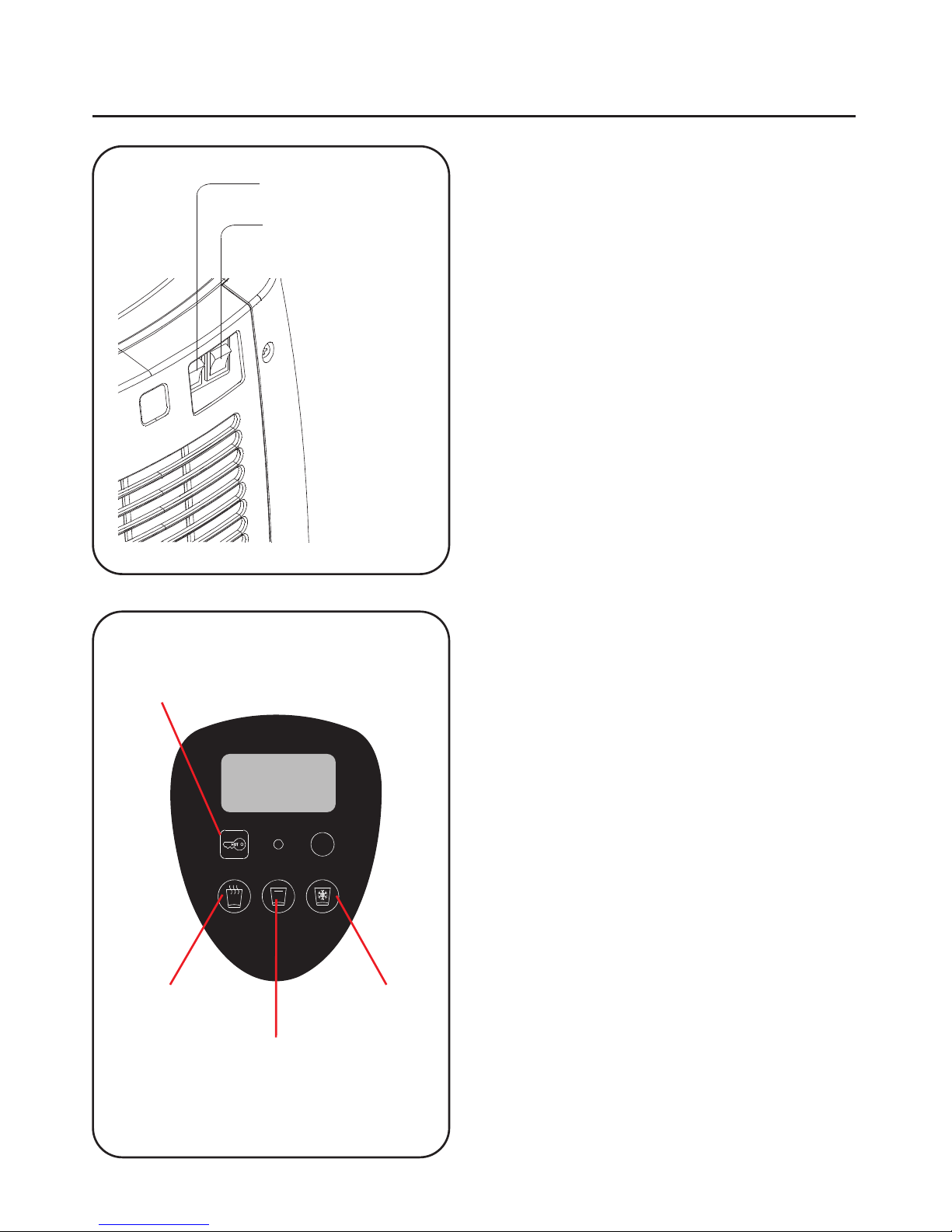
H2O LIFE SOURCE Renaissance REN- HCA2200 User manual

All-in-one Convenience
Cold, Ambient and Hot Water Dispenser with UV
REN- HCA2200
Operation Manual
Operation and Setting 11- 15
Installation
1
Page
10
8, 9
5
3
2
Replacement of UV
Cleaning &Maintenance
Safety Reminder
Directions for Use
Preface / Parts
Contents
Operation Method 4
Replacement of Filter 6, 7
Please read these instructions completely before operating this unit
Ver2_10092018

Top Cover
Drip Tray
Drip Collector
Hot -
Water Button
UV (inside)
Safety Lock
IC Board Control Panel
Ambient -
Water Button
Cold -
Water Button
Preface/Parts
Before using this water dispenser , we advise you to read this manual thoroughly.
Please follow the instructions to ensure proper operation and the lasting of the
dispenser.

Installation
Drawing (A)
Drawing ( B )
Back view
Tri - way Socket
Faucet
Standard Installation of Tap Diverter Valve
Installation using Under Sink
1. Disassemble the original
water tap. Then put on
the tri-way socket and
inlet ball valve. See
drawing (A).
2. Connect the 1/4" PE
water pipe between
inlet ball valve and
inlet connector. See
drawing (B).
1/4” Inlet Ball Valve
1/4” PE Water Pipe
1/4” Inlet Ball Valve
Water In Connector
Inlet Water Pressure
Minimum : 10Psi/68,947 Pa
Maximum : 40Psi/275,790 Pa
Connecting divertor to
ourside threads on faucet
Remove
Existing
Aerator
Swivel
Collar
Gasket
Adapter
Gasket
Adapter
Swivel
Collar
Handle
Handle
Faucet
adapters
(use size as needed)
Diverter valve
Diverter valve
1/4” PE
Water Pipe
2

Safety Reminder
If the supply cord is damaged, it
must be replaced by a special
cord or assembly available from
the manufacturer or its service
agent.
Be sure to use single
outlet socket with
correct power
voltage. Plug the
power cord directly
into electrical
socket.
Leave a space no less than 15cm between
the wall and dispenser.
Keep the machine away
from sunlight, heat, and
wetness.
Caution
1. This appliance is not intended for use by persons (including children) with reduced physical,
sensory or mental capabilities, or lack of experience and knowledge, unless they have been
given supervision or instruction concerning use of the appliance by a person resposible for
their safety.
2. Children should be supervised to ensure that they do not play with the appliance.
3. This appliance is intended to be used in household and similar applications such as
• staff kitchen areas in shops, offices and other working environments.
• farm houses and by clients in hotels, motels and other residential type environments;
• catering and similar non-retail applications.
3

Operation Method
Safety Lock
Cold
Water
Button
Ambient
Water
Button
Hot
Water
Button
Set
1. Turn on the main power switch for
electricity but keep the power switches
for hot and cold water OFF. These
switches are found on the back of the
dispenser.
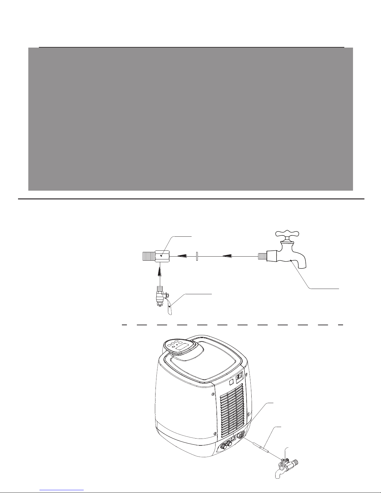
Next, turn on the water supply to allow
water to fill up the tanks in the dispenser.
Takes about 2 to 3 minutes to fill up the
tanks on the inside. Press the cold and
hot water buttons individually to clear
the water from the tanks. Takes about 2
to 3 minutes each to empty the water
from the cold and hot water tanks
completely. You may wish to flush the
tanks once or twice in this manner
before actual use.
Now wait for 2 to 3 minutes for the tanks
to be refilled (this should be an automatic
process as long as the water supply is
switched on at the faucet or under-sink
permanently. If not, manually turn on the
supply to allow water flow). When the
tanks are filled, the dispenser is ready to
for heating and chilling.
2. Turn ON the power switches on the back
of the dispenser. Indications relating to
the hot & cold water will show up on the
LCD as listed on Pages 11 to 15.
3. To drink, select the water you wish to
have by pressing the hot, ambient or
cold temperature buttons.
4. When the hot water is not hot enough,
the water will reheat automatically. To
dispense hot water, remember to press
the Safety Lock button first, then press
the HOT water button to dispense. The
hot water button locks automatically
after 5 seconds.
Hot Power Switch
Cold Power Switch
4

Replacement of UV Lamp
4
2
3
Top Cover
Cover
Set Switch
UV Lamp
1
Push
When hearing the alarm from the dispenser, the WARN sign will flash to indicate
malfunction. To replace UV Lamp, please disconnect the machine from the electricity
before starting any procedures.
First, press the button as directed in #1 to open the top cover. Second, follow steps
#2, #3 and #4 to remove the UV cover. Then take out the used/damaged UV Lamp
and replace with a new one to complete the replacement.
5

Replacement of Filter
1
Twist in clockwise
direction to remove
Top Cover
Push
Twist in Counterclockwise
direction to install
Push
When hearing the alarm from the dispenser, the WARN sign will flash to indicate
filters need to be changed. To replace filters, please turn off the dispenser from the
electricity before starting any procedures.
First, press the button from behind the unit (as directed) in order to open the top
cover. Second. follow steps #2, #3 and #4 to remove the filters. Then, replace with a
set of new filters to complete the replacement
F1 F2
6

Replacement of Filter
Place back the new filter into filter place. Push the filter head down until you hear the
‘click’ sound to secure filter position. Then you need to reset the day counter and
flow meter back to “0000”. Hold the safety lock button and Set switch for 3 seconds
until you hear 5 beep sounds.
Safety Lock
Set Switch
Once the filter counter already reset, you MUST do flushing the new filter for at
least 1-2L by pressing Ambient water button continuously.
Ambient
Water Button
7

Cleaning & Maintenance
B
A
2
1
1. When drip collector is full, the water
dispenser will make 3 long beeping
sounds every 30 seconds. The FULL sign
will be shown on the display. Please
place the drip tray back and press the
drip collector to let it to pop out (shown
by arrow A).
Take out the drip collector and empty
the water inside (shown by arrow B).
Place it back and the dispenser will
provide water again.
2. When the drip collector is full, water
will not come out when pressing the
water buttons.
8

Cleaning & Maintenance
Cold Water Drain
Caps
Hot Water Drain
1. Please make sure the water dispenser is
completely disconnected from electricity
before cleaning.
2. Remove the caps on top of the hot water and cold water drains. The
remaining water in the tanks will drain out. Cleaning may start when both
tanks are emptied. Please put the caps back when cleaning is done.
Caution:
For your safety , please contact your distributor or qualified technician for repairment when
the water dispenser is damaged.
9

Directions for Use
Drip Tray
1
2
This unit may provide water to
containers of all sizes. When filling
a small container or cup, simply open
the drip tray (as shown).
If the container is taller or bigger,
please keep the drip tray and fill it
directly under the dispensing point
(as shown)
10

Operation and Setting
1. Machine On
All functions and signs on the screen are shown. Then according to each model to
display its functions, cold and hot temperature, UV, Filter and enegy saving indicator.
2. Descriptions
Hot water in use.
The 98oC next to it is the hot water temperature.
When heating the water, the color bar flashes.
Cold water in use.
The 5oC next to it is the cold water temperature.
When chilling the water, the color bar flashes.
UV in use.
Flow Meter: Showing liters of water produced.
F 1500 L stands for 1500 liters have been produced.
Day Counter: Showing how long the filters were used.
F 0180 Day means the filters were used for 180 days.
Energy saving in use.
Soda in use.
(If no hot water, soda and its temperature appear on the first row.)
Not Applicable for this model
Warning for machine errors.
11
F
HOT
F
COLD
UV
SODA
WARN

Operation and Setting
3. Setting
To adjust hot water temperature, press set one time to indicate
current hot water temperature. Press set again and hold for 3
seconds the temperature may be changed from 80 to 100oC.
Default setting is 100. To complete setting, press set and hold
for 3 seconds. If no button is pressed, the unit saves the setting
automatically after 30 seconds.
SET
Safety Lock
To adjust cold water temperature, press set 2 times to indicate
current cold water temperature. Press set again and hold for 3
seconds, the temperature may be changed from 2 to 8oC.
Default setting is 2.
To adjust surrounding brightness, press set 3 times to indicate
current brightness level. Press the internal switch and hold for
3 seconds, the brightness level may be changed from 0 to 5.
Default setting is 3. ( 0 = the darkest, 5 = the brightest )
Set
Set Set
Set
12

Operation and Setting
4. Energy Saving
5. Reboil On/Off
Set
HOT +
Set
HOT
Set
HOT +
Turn on
Turn off
When energy saving is off, hold the lock button and press set to turn on.
When energy saving is on, hold the lock button and press set to turn off.
• Energy saving will turn on or off the heating system according to the current
setting of brightness level.
• If the surrounding is darker than the current setting level, the heating system will
turn off after 10 minutes.
• If the surrounding is brighter than the current setting level, the heating system
will activate after 1 minute.
Press the lock button. Within 5 seconds, press Set to activate
reboil. A short beep sound will be heard and the hot water
color bar on the screen flashes as to indicate heating in
process.
When reboil starts, it will not stop till water reaches 100oC. To
stop heating, press lock and then press set.
6. Reset Day Counter and Flow Meter (After Changing Filter)
To reset the counters back to zero, hold the lock button and the internal switch for 3
seconds. The unit will make 5 beeping sounds and clear the record of the counters.
When energy saving is on, the hot temperature will
appear as - - , and the color bar is not showing.
13

Operation and Setting
7. Errors
Problem to the hot temperature control, not connected or over 105oC.
Temperature rises too quickly or empty heating. Will return to normal when
water is added. Please contact distributor when error keeps appearing.
Constant heating for 1 hour or not reaching the set temperature. If water is
added during the heating, the timer starts over.
Problem to the cold temperature control, not connected or over 70oC.
Constant chilling for 8 hours or not reaching the set temperature.
Fan error, disconnected or damaged.
Leaking detected on the bottom plate. Please reconnect to electricity.
Water-in solenoid valve or related parts damaged, might cause leaking.
IC board self testing. Problem with electro voltage.
Providing water for over 40 seconds or buttons jammed. Remove button
jam to return to normal status.
Drip collector is full over 3 seconds. Drain the collector to return to
normal status.
C101
C102
C103
C201
C202
C203
C301
C302
C303
OFF
FULL
8. Alarm and Malfunctions
When C101 to C302 appears, chilling and heating systems are both off. When C101
to C202 appears, water may still be provided. The unit will make short beeping
sounds when malfunctions occur, please restart to stop the alarm.
When C301, C302, C303 or OFF appears, water supply and power system will be off.
This unit makes alarm sounds when the following conditions happen:
OFF, FULL, UV malfunction, and change filters.
The alarm will be 3 long beeps every 30 seconds and WARN flashes on the display.
To stop the alarm, just press set. WARN sign will be gone for 10 seconds. After 10
seconds, WARN flashes again until the problem is solved. During this time, if other
problems are detected, the alarm will beep again.
14

For more information, please contact our
H2O LIFE SOURCE office:
H2O LIFE SOURCE (SEA) PTE LTD
No 38 Jalan Pemimpin
#06-02 @ M38 Singapore 577178 SINGAPORE |MALAYSIA | PHILIPPINES |
MYANMAR | THAILAND | AUSTRALIA
www.h2olifesource.com
+65 8100 6600
WhatsApp
For more advanced technical support,
Operation and Setting
9. Others
1. When chilling reaches the set temperature, the fan will run for another five minutes.
2. All settings are stored in memory.
3. When errors happen to the LCD display, the unit will reset every five seconds till
recover from the problems.
Note: IC board of LCD will reset when 1Kv electric shock occurs. The display reappears again
after 5 seconds.
4. When the fan is stucked, the alarm will activate after 5-15 seconds due to voltage
control. The fan and its component will not damage immediately, but the temperature
will gradually goes up. The alarm signal will appear as 203 on the display for safety
concern.
5. When the fan is damaged, burnt off, short circuit, or disconnected, alarm signal 203
will appear. Please be aware that when unable to dissipate heat will cause damages
to the compressor.
6. IC board and the fan will perform self testing when each time the unit is on.
7. Fan control wiring improved. The power lowers automatically from 33V to 24V to
reduce noisy as well as the squeaky sound.
8. When power parts are not working normally and cause the unstable internal power,
the IC board may still work properly. But to avoid all parts from bearing high
voltage, the alarm will indicate 303 on the display.
9. Alarm 302 -- 2 problems as listed below
Error occurs to water supply system, either certain parts not working properly or
short circuit of water-out solenoid valve.
a. Parts not working -- alarm goes on when solenoid valve is on for over 5 seconds
b. Solenoid valve short circuit -- alarm goes on immediately
Normally, solenoid valve and the switch on the IC board are not electrified
when not being pressed.
Table of contents
Other H2O LIFE SOURCE Water Dispenser manuals
Popular Water Dispenser manuals by other brands

BRIO
BRIO CLBLT620BLK Installation and operation manual

Pentair
Pentair FLECK 2900S Service manual

Watts Premier
Watts Premier Sof-Tek Installation, operation and maintenance manual

Ultra
Ultra ECO & ECO Installation & operating instructions

Newa
Newa Duetto DJ50 Instructions and warranty

Rheem
Rheem RHW42 Installation and operation manual