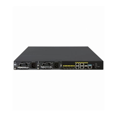
H3C CR16000-M User manual

H3C CR16000-M Routers
Installation Guide
New H3C Technologies Co., Ltd.
http://www.h3c.com
Document version: 5W101-20221206

Copyright © 2022, New H3C Technologies Co., Ltd. and its licensors
All rights reserved
No part of this manual may be reproduced or transmitted in any form or by any means without prior
written consent of New H3C Technologies Co., Ltd.
Trademarks
Except for the trademarks of New H3C Technologies Co., Ltd., any trademarks that may be
mentioned in this document are the property of their respective owners.
Notice
The information in this document is subject to change without notice. All contents in this document,
including statements, information, and recommendations, are believed to be accurate, but they are
presented without warranty of any kind, express or implied. H3C shall not be liable for technical or
editorial errors or omissions contained herein.
Environmental protection
This product has been designed to comply with the environmental protection requirements. The
storage, use, and disposal of this product must meet the applicable national laws and regulations.

Preface
This document describes the installation procedure for the CR16000-M routers. It includes safety
precautions, preparing for installation, installing the router, installing modules, connecting cables,
starting and configuring the router, replacing modules, troubleshooting, engineering labels, cable
assembling and management, and repackaging procedures.
This preface includes the following topics about the documentation:
•
Audience.
•
Conventions.
•
Documentation feedback.
Audience
This documentation is intended for:
•
Network planners.
•
Field technical support and servicing engineers.
•
Network administrators working with the CR16000-M routers.
Conventions
The following information describes the conventions used in the documentation.
Command conventions
Convention
Description
Boldface
Bold
text represents commands and keywords that you enter literally as shown.
Italic Italic text represents arguments that you replace with actual values.
[ ] Square brackets enclose syntax choices (keywords or arguments) that are optional.
{ x | y | ... }
Braces enclose a set of required syntax choices separated by vertical bars, from which
you select one.
[ x | y | ... ]
Square brackets enclose a set of optional syntax choices separated by vertical bars,
from which you select one or none.
{ x | y | ... } *
Asterisk marked braces enclose a set of required syntax choices separated by vertical
bars, from which you select a minimum of one.
[ x | y | ... ] *
Asterisk marked square brackets enclose optional syntaxchoices separated byvertical
bars, from which you select one choice, multiple choices, or none.
&<1-n> The argument or keyword and argument combination before the ampersand (&) sign
can be entered 1 to n times.
# A line that starts with a pound (#) sign is comments.
GUI conventions
Convention
Description
Boldface Window names, button names, field names, and menu items are in Boldface. For
example, the
New User
window opens; click
OK
.

Convention
Description
> Multi-level menus are separated by angle brackets. For example, File > Create >
Folder.
Symbols
Convention
Description
WARNING!
An alert that calls attention to important information that if not understood or followed
can result in personal injury.
CAUTION:
An alert that calls attention to important information that if not understood or followed
can result in data loss, data corruption, or damage to hardware or software.
IMPORTANT:
An alert that calls attention to essential information.
NOTE:
An alert that contains additional or supplementary information.
TIP:
An alert that provides helpful information.
Network topology icons
Convention
Description
Represents a generic network device, such as a router, switch, or firewall.
Represents a routing-capable device, such as a router or Layer 3 switch.
Represents a generic switch, such as a Layer 2 or Layer 3 switch, or a router that
supports Layer 2 forwarding and other Layer 2 features.
Represents an access controller, a unified wired-WLAN module, or the access
controller engine on a unified wired-WLAN switch.
Represents an access point.
Represents a wireless terminator unit.
Represents a wireless terminator.
Represents a mesh access point.
Represents omnidirectional signals.
Represents directional signals.
Represents a security product, such as a firewall, UTM, multiservice security
gateway, or load balancing device.
Represents a security module, such as a firewall, load balancing, NetStream, SSL
VPN, IPS, or ACG module.
T
T
T
T

Examples provided in this document
Examples in this document might use devices that differ from your device in hardware model,
configuration, or software version. It is normal that the port numbers, sample output, screenshots,
and other information in the examples differ from what you have on your device.
Documentation feedback
You can e-mail your comments about product documentation to info@h3c.com.
We appreciate your comments.

i
Contents
1 Safety precautions···················································································1-1
Safety labels····················································································································································1-1
Basic safety guidelines····································································································································1-2
Local laws and regulations······················································································································1-3
Basic requirements ·································································································································1-3
Grounding requirements ·························································································································1-3
Personal safety ·······································································································································1-3
Device safety···········································································································································1-4
Installation site ················································································································································1-4
Basic requirements ·································································································································1-4
Indoor installation····································································································································1-4
Installation in a rack ································································································································1-5
Electrical safety···············································································································································1-5
High voltage············································································································································1-5
High leakage current·······························································································································1-5
AC and DC power supply························································································································1-5
Power cables···········································································································································1-6
Cabling····················································································································································1-6
TNV circuit···············································································································································1-6
ESD·························································································································································1-7
Laser safety·····················································································································································1-7
Mechanical safety ···········································································································································1-8
Drilling holes············································································································································1-8
Sharp objects··········································································································································1-8
Fan trays·················································································································································1-8
Moving heavy objects······························································································································1-8
Hoisting safety·········································································································································1-9
Card installation and cable connection ·········································································································1-10
Installing and removing a card··············································································································1-10
Bundling cables·····································································································································1-10
Cabling under a low temperature··········································································································1-11
1-1
1 Safety precautions
To avoid possible bodily injury and device impairment, read the following safety recommendations
carefully before installing your device. In actual installation, you need to take safety measures
including but not limited to the safety recommendations listed in this section.
•
Safety labels
•
Basic safety guidelines
•
Installation site
•
Electrical safety
•
Laser safety
•
Mechanical safety
•
Card installation and cable connection
Safety labels
Carefully identify the safety labels on the device before you use the device, and follow the
instructions on the labels to operate the device.
Table1-1 Safety label description
Label Name Description
ESD ESD sensitive device.
Grounding Grounding point of the device. If a separate
grounding point is available, you must connect the
grounding point to the earth permanently.
Fan tray alarm label
•Do not touch rotating fan blades before a fan
tray stops.
•Hazardous rotating component.
•Stay away from rotating fan blades.
•Operate this component 1 minute after this
component is removed or the device is
powered off.
Hot surface
•The surface is of high temperature.
•Hot surface. Do not touch it.
•Operate this component 1 minute after this
component is removed or the device is
powered off.
Altitude The device can operate correctly in an area with an
altitude lower than 2000 m (6561.68 ft).

1-2
Label Name Description
Non-tropical climate The device can operate correctly only in a
non-tropical climate.
Read instruction
manual Read the instruction manual for how to operate the
device.
Weight-supporting
handle
To lift a chassis with a weight higher than 100 kg
(220.46 lb), read the instruction manual and use
tools.
Laser safety Invisible laser radiation with a hazard class of 1M.
Do not view directly with non-attenuating optical
instruments.
Multiple power
sources
•The device has multiple power sources.
•
To power off the device, you must shut down all
power sources.
•Disconnect all power cables, including RPS.
High leakage current High leakage current. You must ground the device
before you connect it to the power source.
The safety labels vary depending on the device model. The labels in this section are for illustration
only.
Basic safety guidelines
Installation and removal of the unit and its accessories must be carried out by qualified personnel.
You must read all of the Safety Instructions supplied with your equipment before installation and
operation.
Before any operation is performed, please read the operation instructions and precautions carefully
to minimize the possibility of accidents. The Note, Caution, and Warning items in other manuals do
not cover all safety precautions that should be followed. They are only the supplements to the safety
precautions for operations as a whole. Therefore, the personnel in charge of the installation and
maintenance of the products are required to understand these basics of safety operation.
To avoid device failure, use the device only in an environment that meets the design specifications.
Device anomalies, component damage, personal safety accidents, or property damage are not
covered by the warranty.

1-3
Local laws and regulations
Comply with local laws and regulations. The safety precautions in this document are only
supplements to the local laws and regulations.
Basic requirements
Only trained and qualified personnel are allowed to install and maintain H3C devices. Note the
following guidelines during installation, operation, and maintenance of the device:
•
The personnel to install or maintain H3C devices must be trained and familiar with correct
operation skills and all safety preventive measures. Only qualified personnel can install and
maintain the device.
•
Only qualified personnel can remove safety facilities and maintain devices.
•
Only H3C certified or authorized personnel can replace devices or components and perform
software upgrade.
•
Operators must report failures or errors that might lead to safety issues to people in charge in
time.
Grounding requirements
•
When you install the device, make sure the ground connection is always made first and
disconnected last.
•
Never defeat the ground conductor.
•
Never operate the device in the absence of a suitably installed ground conductor.
•
Before you operate the device, make sure the device is grounded reliably.
Personal safety
•
To avoid electric shocks, do not connect a safety extra low voltage (SELV/ES1) terminal to a
communication network voltage (TNV/ES2) terminal.
•
To avoid possible eye damage, do not stare into the fiber port without eye protection.
•
To avoid possible electrical shocks or injury, wear ESD clothes, ESD gloves, and ESD wrist
strap, and remove any jewelry or watches before you operate the device.
•
In the event of fire, evacuate the equipment room and pull the fire alarm or call your local
emergency number. Never go back into a burning building.

1-4
Device safety
•
Attach the device on the ground or other secure places.
•
Do not block the air vents when the device is operating.
•
Use tools rather your hands to fasten screws.
•
Remove all packing materials from the equipment room after the installation is complete.
•
Shut off the power before you can install or move a power supply.
Installation site
Basic requirements
Make sure the installation site meets the following requirements:
•
The installation must be compliant with local laws and regulations.
•
Make sure the installation environment meets the specifications as required by the device, such
as ground load bearing, temperature, humidity, cleanliness, anti-interference, grounding, power
supply, ventilation, and space.
•
To ensure correct operation and long service life of the device, make sure the installation site is
free from flammable and explosive, acid, and alkaline gases, and harmful gases such as SO2,
H2S, NH3, Cl2, and NO2.
•
To prevent fire caused by high temperature, do not install the device near heat sources, such as
stoves, ovens, microwaves, and electric heaters.
•
To prevent fire caused by high temperature, do not use flammable materials such as paper and
cotton to shield or cover the device when it is operating.
•
Do not use devices with electrical equipment protection rating lower than IP54 outdoors.
Indoor installation
•
To prevent water from entering the device and causing device failure, make sure no water
leakage or condensation can occur on top of the equipment room because of air conditioning
failures.
•
If the device has large openings at the bottom for installation on the ground, you must install the
device on concrete, tile or other non-combustible surfaces.
•
Prevent rodent and pest infestations at the installation site.

1-5
Installation in a rack
•
Check the earthing and stability of the rack, and make sure there is no obstacle inside or near
the rack that might hamper the installation.
•
Reserve sufficient space around the rack. For a closed rack, make sure the rack has good
ventilation.
Electrical safety
High voltage
Direct contact or contact through wet objects with high voltage power can result in fatal hazard.
Incorrect high voltage operation can cause fire and electric shock.
High leakage current
WARNING
!
To avoid bodily injury or device damage, ground the device before powering it on if a "high leakage
current" label is attached to the power terminal on the device.
AC and DC power supply
WARNING
!
•
Direct contact or contact through wet objects with the power source can result in electric shock.
•Incorrect operation might cause accidents such as fire and electric shock.
•
If the device uses AC power input, each power supply must have a separate circuit breaker.
•
This device is suitable for TN power systems. It cannot be powered by an IT power system. If
your supplies are of the IT type, this unit must be powered by 230V (2P + T) via a 1:1 ratio
isolation transformer, and the Neutral wire on the secondary point must be connected to the
earth (ground) directly.
•
For devices that use a DC power source, use reinforced insulation or double insulation to
isolate the DC power source from the AC mains supply.
•
For devices that use an SELV/ES1 DC power source, use SELV/ES1 power source compliant
with IEC60950-1/IEC 62368-1.
•
For devices that use a DC power source, provide circuit breakers compliant with local power
supply regulations and make sure the circuit breakers are always available.
•
The device comes with high-voltage DC power supplies. Please use supplied or recommended
power cables to connect the power supplies.

1-6
•
If there is any possibility that you might touch a live part on the device, you must disconnect
power from the upper-level equipment of that live part.
•
Before connecting a power cable, verify that the input voltage is within the rated voltage range
of the device.
•
Before connecting a power cable, check the cable and terminal for reversed polarities.
•
Before powering on the device, make sure electrical connections are correct.
Power cables
WARNING
!
Do not connect or remove power cables when the device is operating. If you do so, electric arcs or
sparks might cause fire or hurt your eyes.
•
To avoid short circuit and bodily injuryor fire, always check that the insulation of the power cable
is not damaged.
•
Before connecting or removing a power cable, turn off the power switch.
•
Before connecting a power cable, verify that the label on the power cable is correct.
•
The power cable kits must meet the local certification requirements.
Cabling
•
Using a cable in a high-temperature environment might cause the insulation layer to deteriorate
and break. Leave sufficient distance between cables and the heat-generating devices.
•
After a power cable is led into the equipment room, install a power surge protector that meets
the local industry standards and connect it to the grounding terminal.
•
Route and bind power cables, grounding cables, and signal cables separately. For parallel
cabling, make sure the space between cables is not less than 30 mm (1.18 in).
•
Route grounding cables indoor or bury them in the earth. Do not route a grounding cable from
outdoor or from near the tower foot.
•
Do not route cables through the air outlet vents in the rack.
TNV circuit
•
To avoid electric shocks, do not connect a safety extra low voltage (SELV/ES1) circuit to a
communication network voltage (TNV/ES2) circuit.
•
Do not operate the device or cables in lightning conditions.

1-7
ESD
•
Wear anti-static clothes and shoes in work areas, and wear anti-static wristbands or anti-static
gloves, and use anti-static tools when operating the device.
•
Clean up materials that can generate static electricity, including ordinary plastic bags, foam-like
materials, plastic products, and adhesive tape to keep them at least 1 m (3.28 ft) away from the
cabinet and devices.
•
When you operate a card, hold the ejector lever or external metal shield of the card. Do not
touch the ports or sockets on a card with your bare hands or any metal component. Do not
touch the printed lines, solder joints, or pins on a component or PCB.
•
All conductors in the equipment room must be grounded reliably.
Static electricity generated by the human body can damage static-sensitive components on a card,
for example, large-scale integrated circuits (LSIs).
Laser safety
To avoid laser radiation, follow these guidelines:
•
Only trained and qualified personnel can perform laser-related operations.
•
Do not remove the dust plugs from a transceiver module until you are ready to connect optical
fibers to it.
•
Install a dust cap on a fiber port if no transceiver module is installed in that fiber port.
•
Wear goggles when you operate a fiber port or fiber cable.
•
Use the shutdown command in interface view at the CLI to shut down a fiber port before you
remove the optical fiber from that fiber port.
•
Never look into a fiber or the ends of a fiber connector unless you know for sure that there is no
laser light in that fiber.
•
You can use an optical power meter to measure the optical power to ensure that the light source
is turned off.
•
Do not use optical instruments such as microscopes, magnifying glasses, or inch glasses to
view the ends of fiber optic connectors or fibers.

1-8
Mechanical safety
Drilling holes
CAUTION:
Do not drill holes in the
cabinet yourself. Incorrect drilling operations can affect EMI shielding
performance of the cabinet and damage cables inside the cabinet. Metal shavings or debris from
drilling can cause a short circuit on the circuit boards.
•
Remove all cables inside the cabinet before you drill holes in the cabinet.
•
Wear goggles and protective gloves when drilling holes.
•
Prevent metal shavings from entering the cabinet when you drill holes. Clean up metal shavings,
if any after drilling holes in the cabinet.
Sharp objects
Wear protective gloves when you move the device to protect yourself from cuts.
Fan trays
•
To prevent damage to fan trays or the device, place the component, screws, and tools in a safe
place when you replace a component.
•
To avoid hurting your fingers or damaging the device, keep your fingers and the component
away from the spinning fan blades when you replace a component around a fan tray.
Moving heavy objects
WARNING
!
•
To avoid bodily injury, be cautious when you move heavy objects.
•
To avoid bodily
injury, pay attention to the unstable or heavydevices in the cabinet when pulling a
chassis out of the cabinet.
•
The handles on a device with a no handling label attached are used onlyfor adjusting the location
of the device. To lift the chassis, use tools.
When moving heavy objects, wear protective gloves to protect against sharp edges and follow these
guidelines:
•
Power off the device, remove all cards from the device, and remove all the external cables
(including power cables) before moving the chassis.
•
Moving the chassis requires a minimum of four people. As a best practice, use a mechanical lift.
•
Lift and put down the chassis slowly and never move suddenly.

1-9
•
Never move suddenly or twist your body. Move the router at stable and consistent paces with
your peer. Keep balance of your body.
•
Stack devices according to the sizes of and packing symbols on the packages.
Table1-2 Packing symbols
Symbol Description
Stored with a maximum stack of n units.
Transported and stored with the arrows up.
Transported and stored with care.
Transported and stored avoiding humidity, rains and wet floor.
Hoisting safety
WARNING
!
Do not walk under the cantilever or hoisted objects when heavy objects are being hoisted.
•
Only trained and qualified personnel can hoist heavy objects.
•
Before hoisting heavy objects, verify that you have all the required hoisting tools and the tools
are in good condition.
•
Before hoisting a heavy object, make sure the hoist is secured on an object or wall that can
support the weight of the object.
•
Make sure the sling angle between the two ropes is not larger than 90 degrees.

1-10
Figure1-1 Hoisting heavy objects
Card installation and cable connection
Installing and removing a card
•
To avoid damage to the components on a card, do not touch the surface of a card, including
parts, circuits, and connectors.
•
To avoid short-circuit or scratching on cards, prevent the surface of a card from contacting the
surface of another.
•
Install a filler panel in the slot without a card installed.
•
Wear ESD gloves or an ESD wrist strap when you install a card. Use proper force to prevent the
pins on the card from being damaged.
Bundling cables
•
Bind and put the cables inside the cabinet in a straight and neat way. No intertwinement or
bending is allowed.
•
Route and bundle different types of cables (power cables, signal cables, ground wire)
separately. If they are close to each other, you can route them in cross-shape. For parallel
cabling, make sure the space between power cables and signal cables is not less than 30 mm
(1.18 in).
•
The cable binding rack and cabling channel inside and outside the cabinet must be smooth and
without sharp edges or tips.
•
The metal cable management hole must have a smooth and fully rounded surface or wear an
insulating bush.
•
Use the right type of ties to bundle the cables. Do not bundle cables with joined ties.

1-11
•
Cut the extra parts of the ties neatly after bundling the cables, leaving no sharp or angular tips.
Cabling under a low temperature
When the temperature is very low, a violent impact or vibration might damage the cable sheathing.
To ensure safety, comply with the following requirements:
•
Make sure you attach and connect cables at a temperature higher than 0°C (32°F).
•
If a cable is stored at a place with a temperature lower than 0°C (32°F), allow a 24-hour
warm-up period to bring it to normal operating temperature before connecting it to the device.
•
Be cautious when you handle cables, especially at a low temperature. Do not drop cables
directly from the vehicle.

i
Contents
2 Preparing for installation··········································································2-1
Preparing the installation site··························································································································2-1
Weight support········································································································································2-1
Temperature and humidity······················································································································2-1
Cleanliness··············································································································································2-2
Harmful gas limit ·····································································································································2-2
EMI··························································································································································2-2
Grounding ···············································································································································2-3
Power supply···········································································································································2-3
Cooling····················································································································································2-3
Space······················································································································································2-4
Unpacking and inspecting the router ··············································································································2-5
Pre-unpacking inspection························································································································2-5
Unpacking and inspecting the chassis····································································································2-6
Unpacking and inspecting removable components·················································································2-6
Inspecting modules·········································································································································2-7
Tools and equipment·······································································································································2-8
Measuring and marking tools··················································································································2-8
Drills························································································································································2-8
Fastening tools········································································································································2-8
Fitter tools ···············································································································································2-9
Auxiliary tools··········································································································································2-9
Fiber-optic cleaning tools······················································································································2-10
Equipment·············································································································································2-10

2-1
2 Preparing for installation
Preparing the installation site
Before installing the router, inspect and prepare the installation site to be sure that the router will
work in a good operating environment. For the operating environment requirements of the router, see
Generic Operating Environment Requirements of H3C Devices Installed Indoors.
Weight support
Make sure the floor or ground at the installation site can support the combined weight of the router
and the rack. The total weight of the router includes the chassis and its components (for example,
modules and power supplies) and accessories. For information about the weights of the router and
its components, see H3C CR16000-M Routers Hardware Information and Specifications.
TIP
:
To assess the load
-bearing requirements for the floor, take potential system expansion (for
example, adding more modules) also in consideration.
Temperature and humidity
CAUTION:
If condensation
occurs on the chassis after you move it from a lower temperature to a higher
temperature, dry the chassis before powering it on to avoid short circuits.
Adverse temperature and humidity conditions in the equipment room will accelerate the aging of
devices and reduce the capability of the device to withstand harsh environment conditions.
•
Lasting high relative humidity can cause poor insulation, electricity leakage, mechanical
property change of materials, and metal corrosion.
•
Lasting low relative humidity can cause washer contraction and ESD and bring issues including
loose screws and circuit failure.
•
High temperature can accelerate aging of insulation materials and significantly lower the
reliability and lifespan of the router.
•
Lasting high temperature and relative humidity can aggravate corrosion of corrosive gas and
particles to the bare parts of the device and significantly reduce the service life of the device.
To prevent the preceding issues, maintain the temperature and humidity in the equipment room in
the ranges as described in Table2-1.
Table2-1 Temperature and humidity requirements
Item Operating Storage
Temperature 0°C to 45°C (32°F to 113°F) –40°C to +70°C (–40°F to +158°F)
Relative humidity 5% to 95%, noncondensing 5% to 95%, noncondensing

2-2
Cleanliness
Dust buildup on the chassis might result in electrostatic adsorption, which causes poor contact of
metal components and contact points. In the worst case, electrostatic adsorption can cause
communication failure.
Table2-2 Dust concentration limits in the equipment room
Substance Particle diameter Concentration limit
Dust particles ≥ 0.5 µm ≤ 1.8×10⁷particles/m3
Harmful gas limit
Corrosive gases can accelerate corrosion and aging of components. Make sure the corrosive gases
do not exceed the concentration limits as shown in Table2-3.
Table2-3 Corrosive gas concentration limits
Gas Average concentration (mg/m3) Maximum concentration (mg/m3)
SO20.3 1.0
H2S 0.1 0.5
Cl20.1 0.3
HCI 0.1 0.5
HF 0.01 0.03
NH31.0 3.0
O30.05 0.1
NOX0.5 1.0
EMI
All electromagnetic interference (EMI) sources, from outside or inside of the router and application
system, adversely affect the router in the following ways:
•
A conduction pattern of capacitance coupling.
•
Inductance coupling.
•
Electromagnetic wave radiation.
•
Common impedance (including the grounding system) coupling.
To prevent EMI, use the following guidelines:
•
If AC power is used, use a single-phase three-wire power receptacle with protection earth (PE)
to filter interference from the power grid.
•
Keep the router far away from radio transmitting stations, radar stations, and high-frequency
devices.
•
Use electromagnetic shielding, for example, shielded interface cables, when necessary.
•
To prevent signal ports from getting damaged by overvoltage or overcurrent caused by lightning
strikes, route interface cables only indoors.
Other manuals for CR16000-M
1
Table of contents
Other H3C Network Router manuals

H3C
H3C S3100 Series Installation instructions

H3C
H3C MSR 900 Series User manual

H3C
H3C S3100-52P User manual

H3C
H3C SR8800-X User manual

H3C
H3C SR6600 Series User manual

H3C
H3C CR16006-F Quick guide

H3C
H3C S3100-52P User manual

H3C
H3C MSR Series User manual

H3C
H3C MSR 2600 Operating and maintenance manual

H3C
H3C SR6600 SPE-FWM Installation manual

H3C
H3C CR16000-F Operating and maintenance manual

H3C
H3C SR6600 SPE-FWM User manual

H3C
H3C SR6608 User manual

H3C
H3C MSR 5660 Use and care manual

H3C
H3C SR6600 SPE-FWM User manual

H3C
H3C S3100-52P User manual

H3C
H3C CR16000-F User manual

H3C
H3C AR 46-80 User manual

H3C
H3C S7500 Series User manual

H3C
H3C SR6600 SPE-FWM User manual