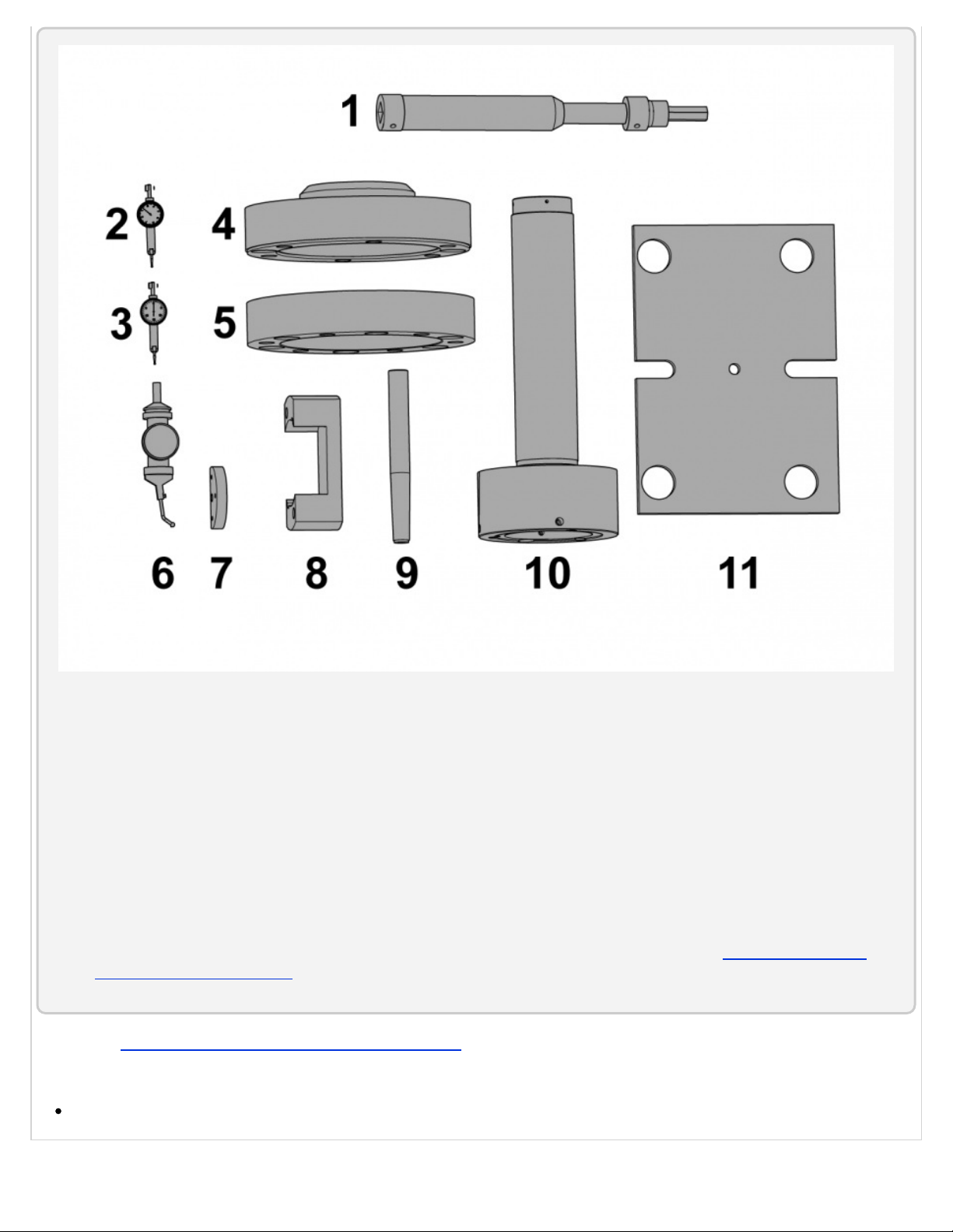
Haas Automation ST User manual

ST, DS - Alignment Correction - Introduction
Correct lathe alignment makes a common centerline through the spindle [1], the turret pocket [2], and the tailstock [3] or
secondary spindle. If the turret crashes, the lathe can lose its alignment. This procedure tells you how to correct the lathe
alignment. For clarity, the illustrations hide surrounding components.
Prerequisites
Make sure the machine is level. Refer to the Lathe Leveling Video.
Haas Technical Documentation
ST, DS - Alignment Correction
Scan code to get
the latest version
of this document
Translation
Available
Applies to machines built from:
June, 2010
Copyright 2018 by Haas Automation, Inc. No unauthorized reproduction | Last Published On November 05, 2015 1/67

Tools Required:
1. T-0025 - 5/8" Hex Extension for ST-20/30 Spindle Head
2. 0.0001-inch (0.002 mm) indicator
3. 0.0005-inch (0.01 mm) indicator
4. Spacer for the Spindle Alignment Tool (for ST-40 Big Bore only)
5. Adapter for the Spindle Alignment Tool (for ST-40 Big Bore only)
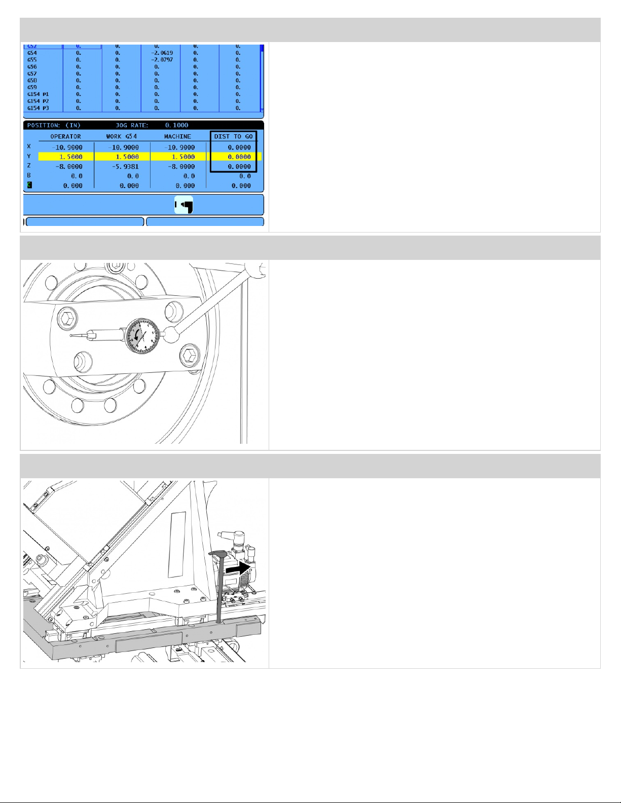
6. 0.0005-inch (0.01 mm) Coaxial indicator. The indicator shaft size must be 0.375 inches (9.525 mm), to fit into the
coaxial indicator mount (T-0017).
7. T-0017 - Coaxial Indicator Mount
8. Face Indicator Tool
9. Tailstock Alignment Tool
10. Spindle Alignment Tool
11. Optional: Spindle Head Alignment Tool (for ST-20/30, DS-30 only). To make this tool, refer to ST-20, ST-30, DS-30
Spindle Head Alignment Tool. To attach this tool you need a 1/2-13x1 flat head cap screw.
Refer to the Field Service Lathe Level and Alignment Checklist for the part numbers of these alignment tools for each lathe model.
Parts Required:
(6) Rail Plugs (P/N 20-4300)
Copyright 2018 by Haas Automation, Inc. No unauthorized reproduction | Last Published On November 05, 2015 2/67

ST, DS - Spindle Centerline to Z Axis Parallelism Correction
This section tells how to correct the alignment of the spindle housing [1] to the Z Axis travel [2].
STEP 1
Refer to ST, DS - Spindle Centerline to Z Axis Parallelism Check to
measure the alignment on the top of the alignment tool.
If the error is greater than 0.0004" (0.01 mm) per 10" (254 mm), correct
the alignment in the steps that follow.
Note: This adjustment is rare. If the error is greater than 0.0004"
(0.01 mm), measure the alignment again. Make sure the
alignment tool is aligned and make sure your indicator setup is
stable.
Copyright 2018 by Haas Automation, Inc. No unauthorized reproduction | Last Published On November 05, 2015 3/67

ST, DS - Y Axis Square to Z Axis Correction
This section corrects the squareness of the Y-Axis [1] to the spindle centerline [2]. This procedure applies only to machines with
the Y-Axis option.
STEP 1
Measure the squareness of the Y Axis to the Z Axis. Refer to ST, DS - Y
Axis Square to Z Axis Check .
Note: This procedure is very similar to the procedure ST, DS - X
Axis to Z Axis Squareness Correction.
Copyright 2018 by Haas Automation, Inc. No unauthorized reproduction | Last Published On November 05, 2015 14/67

STEP 2
Look at the indicator to see the amount and the direction of the error.
STEP 3
Press [ZERO RET] to set the [DIST TO GO] values to 0. Press [HAND
JOG] to see the coordinate position display. We will return to this 0 [DIST
TO GO] position in the steps that follow.
STEP 4
Jog the Z Axis a small amount to move the indicator away
from the spindle.
You will jog the X and Y Axes to move the turret to get access
to the screws.
There are (16) screws [1] that attach the saddle to the linear guide trucks
(4 for each truck), and (10) screws [2] that attach the saddle to the
ballscrew nut housing.
Copyright 2018 by Haas Automation, Inc. No unauthorized reproduction | Last Published On November 05, 2015 15/67

STEP 5
Use a screwdriver and a dead blow hammer, or a drill, to remove the
plugs that cover some of the screws.
Note: You must destroy the plugs to remove them.
STEP 6
Jog the X and Y Axes to move the turret to get access to the (10) screws
that attach the saddle to the ballscrew nut housing.
STEP 7
For some of the screws you must use the access holes in the wedge.
There are access holes on the left side [1].
Copyright 2018 by Haas Automation, Inc. No unauthorized reproduction | Last Published On November 05, 2015 16/67

STEP 8
There is an access hole on the inside [1], and there are access holes on
the right side [2].
STEP 9
There is also an access hole in the rear.
Jog the Y Axis to move the access holes to the correct
positions to loosen the screws.
Note: You must jog the X Axis to near the middle of travel to jog
the Y Axis the full distance.
STEP 10
Loosen a small amount the (16) screws [1] that attach the saddle to the
linear guide trucks, and the (10) screws [2] that attach the saddle to the
ballscrew nut housing.
Note: After you loosen the screws, tighten them enough to let
you control the adjustment, but keep them loose enough to let
you correct the alignment. This is approximately 5-10 ft-lb (7-14
Nm).
Copyright 2018 by Haas Automation, Inc. No unauthorized reproduction | Last Published On November 05, 2015 17/67

STEP 11
Tighten (1) screw to approximately 20 ft-lb (27 Nm) to use as a pivot in the
steps that follow.
Note: Keep the pivot screw loose enough to allow the casting to
rotate, but tight enough to prevent unwanted movement.
STEP 12
Note: You can choose any one of the (4) corner screws [1] as the
pivot screw.
STEP 13
Remove (1) screw at the corner opposite to the pivot screw.
Copyright 2018 by Haas Automation, Inc. No unauthorized reproduction | Last Published On November 05, 2015 18/67

STEP 14
Jog the Axes until the [DIST TO GO] values are 0 again.
STEP 15
The indicator shows amount and direction of the error.
STEP 16
Insert a pry bar into the empty screw hole and push the wedge into
alignment.
Copyright 2018 by Haas Automation, Inc. No unauthorized reproduction | Last Published On November 05, 2015 19/67

STEP 17
The saddle moves around the pivot screw.
STEP 18
Push the pry bar while you monitor the indicator to see the correction.
STEP 19
Tighten the (16) screws [1] that attach the saddle to the linear guide
trucks. Tighten to approximately half of the specified torque.
For torque values, refer to Haas Fastener Torque Specifications.
Copyright 2018 by Haas Automation, Inc. No unauthorized reproduction | Last Published On November 05, 2015 20/67

STEP 20
Measure the squareness. If the alignment is not correct, repeat the
previous steps.
STEP 21
If the alignment is correct, tighten the (10) screws [1] that attach the
wedge to the ballscrew nut housing. Tighten to approximately half of the
specified torque.
For torque values, refer to Haas Fastener Torque Specifications.
STEP 22
Measure the squareness.
Copyright 2018 by Haas Automation, Inc. No unauthorized reproduction | Last Published On November 05, 2015 21/67

STEP 23
If the alignment is correct, torque the (16) screws [1] that attach the
wedge to the linear guide trucks.
For torque values, refer to Haas Fastener Torque Specifications.
STEP 24
If the alignment is correct, torque the (10) screws [1] that attach the
wedge to the linear guide trucks.
For torque values, refer to Haas Fastener Torque Specifications.
STEP 25
Replace the plugs (P/N 20-4300) that cover some of the screws.
Caution: Without the plugs, chips can build up in the holes and
the wiper can sweep them into the linear guides and cause
damage.
Copyright 2018 by Haas Automation, Inc. No unauthorized reproduction | Last Published On November 05, 2015 22/67

ST, DS - X Axis to Z Axis Squareness Correction
This section corrects the squareness of the X Axis [1] to the spindle centerline [2].
STEP 1
Refer to ST, DS - X Axis to Z Axis Squareness Check to measure the
squareness of X Axis movement to the Spindle Centerline.
Copyright 2018 by Haas Automation, Inc. No unauthorized reproduction | Last Published On November 05, 2015 23/67

STEP 2
Look at the indicator to see the amount and the direction of the error.
STEP 3
Press [ZERO RET] to set the DIST TO GO values to 0. Press [HAND
JOG] to see the coordinate position display. We will return to this 0 DIST
TO GO position in the steps that follow.
STEP 4
Jog the Z Axis a small amount to move the indicator away
from the spindle.
Jog the X Axis to move the turret to get access to the screws.
Copyright 2018 by Haas Automation, Inc. No unauthorized reproduction | Last Published On November 05, 2015 24/67

STEP 5
Loosen a small amount the (10) screws [1] that attach the wedge to the
ballscrew nut housing.
Note: After you loosen the screws, tighten them enough to let
you control the adjustment, but keep them loose enough to let
you correct the alignment. This is approximately 5-10 ft-lb (7-14
Nm).
STEP 6
Loosen a small amount the (16) screws that attach the wedge to the linear
guide trucks.
Note: After you loosen the screws, tighten them enough to let
you control the adjustment, but keep them loose enough to let
you correct the alignment. This is approximately 5-10 ft-lb (7-14
Nm).
STEP 7
Tighten (1) screw to approximately 20 ft-lb (27 Nm) to use as a pivot in the
steps that follow.
Note: Keep the pivot screw loose enough to allow the casting to
rotate, but tight enough to prevent unwanted movement.
Copyright 2018 by Haas Automation, Inc. No unauthorized reproduction | Last Published On November 05, 2015 25/67

STEP 8
Note: You can choose any one of the (4) corner screws [1] as the
pivot screw.
STEP 9
Remove (1) screw at the corner opposite to the pivot screw.
STEP 10
Jog the X Axis and the Z Axis until the DIST TO GO values are 0.
Copyright 2018 by Haas Automation, Inc. No unauthorized reproduction | Last Published On November 05, 2015 26/67

STEP 11
The indicator shows the amount and direction of the error.
STEP 12
Insert a pry bar into the screw hole and push the wedge into alignment.
STEP 13
The wedge moves around the pivot screw.
Copyright 2018 by Haas Automation, Inc. No unauthorized reproduction | Last Published On November 05, 2015 27/67

STEP 14
Push the pry bar and monitor the indicator to see the correction.
STEP 15
Tighten to approximately half of the specified torque the (16) screws that
attach the wedge to the linear guide trucks.
For torque values, refer to Haas Fastener Torque Specifications.
STEP 16
Measure the squareness.
Copyright 2018 by Haas Automation, Inc. No unauthorized reproduction | Last Published On November 05, 2015 28/67

STEP 17
If the alignment is correct, tighten to approximately half of the specified
torque value the (10) screws that attach the wedge to the ballscrew nut
housing.
For torque values, refer to Haas Fastener Torque Specifications.
STEP 18
Measure the squareness.
STEP 19
If the alignment is correct, torque the (16) screws that attach the wedge to
the linear guide trucks. For torque values, refer to Haas Fastener Torque
Specifications.
Copyright 2018 by Haas Automation, Inc. No unauthorized reproduction | Last Published On November 05, 2015 29/67

STEP 20
If the alignment is correct, torque the (10) screws that attach the wedge to
the ballscrew nut housing.
For torque values, refer to Haas Fastener Torque Specifications.
STEP 21
For machines with a Y Axis, you must align the wedge [1], after you align
the saddle [2], as shown in the previous section.
STEP 22
For machines with a Y Axis, the steps to align the X Axis are the same as
the previous steps.
Loosen the (16) screws that attach the wedge to the linear guide trucks
and the (8) screws that attach the wedge to the ballscrew nut housing.
The only difference is that the (8) screws that attach the wedge to the
ballscrew nut housing are in the rear, as shown [1].
Copyright 2018 by Haas Automation, Inc. No unauthorized reproduction | Last Published On November 05, 2015 30/67
This manual suits for next models
1
Other Haas Automation Industrial Equipment manuals
Popular Industrial Equipment manuals by other brands

Reef Octopus
Reef Octopus Neck Cleaner-110 quick start guide

Blohm + Voss Oil Tools
Blohm + Voss Oil Tools Gray Chain 3570 Technical documentation

Tiger
Tiger TYAA211 User instruction manual

R.V.R. Elettronica
R.V.R. Elettronica SDC2000 user manual

Knick
Knick Ceramat WA160 user manual

ABB
ABB HT576687 Operation manual