Fireye HEP-2-Z Series User manual

© 2022 Carrier 1
CU-124
May 23, 2022
HEP-2
HEP-2-Zxxxx
Portable High-Energy Hand-Held Igniter
(Battery Powered)
OPERATING MANUAL
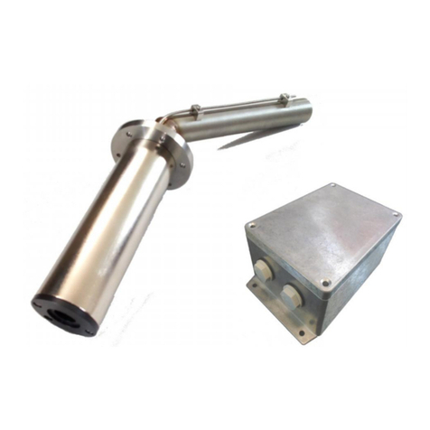
HEP-2 with exible cable in front of the ignition electrode and short ignition tip HE-S
HEP-2-Zxxxx with xed ignition electrode and screwed-on ignition tip HE-S
The operating instructions must be read carefully before installation, commissioning and maintenance.
Instructions must be observed and the operating manual must be kept for later use!

© 2022 Carrier 2
Operating Manual Portable High-Energy Hand-Held Igniter HEP-2
Document Name CU-124 Operating Manual HEP-2
Edition of the manual: First edition: 05/23/2022
Revision Status: A
Last Update
The texts and illustrations have been prepared with the greatest care. Fireye (and the authors) cannot accept any legal
or any other liability for possibly remaining, incorrect or incomplete information and their consequences.
Without prior written permission of Fireye, the documentation or parts thereof may not be reproduced, copied or lent
or passed on to third parties.
Fireye, as supplier of the described portable high-energy hand-held ignition device described, reserves the right to
change the equipment and design of the device modules or individual assemblies at any time - even without prior
notice. The actual availability results from the individual oer created in each case.
No notication will be made if contents are changed.
Illustrations may deviate due to the representation of customer-based special solutions or further developments;
no claim to the delivery of identical products is derived from this.

© 2022 Carrier 3
SAFETY INSTRUCTIONS AND PROTECTIVE MEASURES
Safety during operation and use:
Improper handling can lead to considerable personal injury and damage to property.
Work on the portable high-energy hand-held ignition device may only be carried out by appropriately trained operating
personnel or a qualied electrician.
Operator is a person who is responsible for installing, operating, setting up, maintaining, cleaning, repairing or transporting
equipment and machines so that they can recognize and avoid hazards.
A qualied electrician within the meaning of the accident prevention regulation is someone who, based on their technical
training, knowledge and experience as well as knowledge of the relevant regulations, can assess the work assigned to them
and recognize possible dangers.
The High Energy Portable Igniter (or any part thereof) is not intended for climbing or standing on.
Electromagnetic interference may occur during the ignition period.
Safety during storage, assembly, installation and maintenance:
Proper and safe operation of the device requires proper transport, professional storage, installation and assembly as well as
careful operation.
There is a risk of fatal injury when touching live components, so regular visual inspections must be carried out by the user.
The visual inspection is limited to the intactness of the connected cables, mechanical connections, and the tightness of the
screws. Compliance with the permissible ambient temperatures must be checked.
During ignition, 2kV are applied to the ignition electrode. There is a danger to life if touched!
The portable high-energy hand-held ignition device may only be operated in the combustion chamber with the lid of the
ignition unit closed (and with an undamaged cable, depending on the version) and the ignition electrode installed.
A voltage of 2kV is generated in the ignition unit. If damage is found, the ignition system must be taken out of service and
sent in for repair. Before inspection work, the power supply must be switched o.
The portable high-energy hand-held ignition device requires at least 120 seconds. After this time you can work on the device
There is a risk of burns after pulling the ignition electrode out of the combustion chamber. All components such as internal
parts and the ignition electrode must be cooled down to ambient temperature before removal. The use of protective gloves
and protective work clothing is required.
Protective gloves must be worn when installing the ignition tip. In addition, the risk of crushing when screwing in is pointed
out.
LIMITATIONS OF LIABILITY
The manufacturer accepts no liability for damage due to:
1. Non-compliance of these operating instructions
2. Improper use
3. Use by unqualied or appropriately trained personnel
4. Unauthorized technical and mechanical modications
5. Use of unapproved replacement parts
6. Use of defective and/or improperly repaired devices or parts
7. Repairs by external companies

© 2022 Carrier 4
TABLE OF CONTENTS
Safety instructions and protective measures .......................................................................................................................3
Limitations of liability ........................................................................................................................................................3
Image directory ...................................................................................................................................................................4
General ...............................................................................................................................................................................5
Description .........................................................................................................................................................................5
Necessary components for a complete system ...................................................................................................................6
Assembly Instructions ........................................................................................................................................................7
Applications ........................................................................................................................................................................9
Loading process ................................................................................................................................................................10
Replacing the batteries .....................................................................................................................................................11
Technical specications ....................................................................................................................................................12
Accessories and spare parts ..............................................................................................................................................13
Warranty ...........................................................................................................................................................................14
Liability ............................................................................................................................................................................14
PICTURE DIRECTORY
Individual components HEP-2 with exible cable in front of the ignition electrode .........................................................6
Individual components HEP-2-Zxxxx with xed ignition electrode .................................................................................8
Handle top view ..................................................................................................................................................................9
The ignition start (Ignition) ................................................................................................................................................9
Displays while charging ...................................................................................................................................................10
The polarities must be observed when changing the battery ............................................................................................11

© 2022 Carrier 5
GENERAL
The operating instructions must be read carefully before commissioning. The device generates a life-threatening
voltage of 2kV. Failure to do so may result in personal injury and/or mechanical destruction.
DESCRIPTION
The portable high-energy hand-held ignition device consists of electronics, a 2kV ignition generator and an integrated
battery charger. The HEP-2 series is used for the safe ignition of gas and light oil burners, e.g. in reneries, the steel
industry and in the petrochemical industry. The device is switched ready for operation via a latching switch.
The ignition is started with a button
The device has an LED status indicator and informs the user when the device needs to be recharged.
Two versions are available:
See individual drawings enclosed
1. The HEP-2 is supplied with a pluggable ignition cable, a junction box and the ignition lance with a replaceable igni-
tion tip. The user can determine the required overall length during the initial assembly by using extension tubes.
2. The HEP-2-Zxxxx version is available with a xed ignition lance in two dierent ignition lance lengths. The ignition
tips, which can be ordered separately, are interchangeable.
A power cord and carrying strap are supplied with each HEP-2.

© 2022 Carrier 6
NECESSARY COMPONENTS FOR A COMPLETE SYSTEM
Individual components HEP-2 with exible cable in front of the ignition electrode
HEP-2-Z0750 or HEP-2-Z100 (Highest level, complete system)
HEP-2-PP - Portable high-energy hand-held ignitor with device plug, mains cable and carrying strap
HEP-2-C-1.5 - Ignition cable with handle, ignition tip adapter with high-voltage cable
HE-SSR-0.0 - Ignition tip adapter
HE-S / HE-L - Ignition tip short / long (to be selected depending on the required overall length)
ET 0.0X - Extension tube (to be selected depending on the required total length)
Adjustment of the immersion depth of the ignition electrode above 525mm is made by using optional extension
tubes ET 0.XX and selecting ignition tips HE-S (screwed in 200mm) or HE-L (screwed in 675mm).
Please note that the red high voltage cable is shortened to the required length in the junction box only after all
components have been assembled.
NOTICE:
Due to the pre-assembled high-voltage cable, the electrode length is usually 3 m and can be longer if required.
In this case, please contact Fireye.
WARNING: ATTENTION HIGH VOLTAGE!
Before mounting, replacing the ignition tip or opening the ignition unit, it is absolutely necessary to switch o the
high-energy ignition unit in order to prevent unintentional ignition. Due to the discharge time of the capacitors,
work on the ignition electrode as well as opening the cover may be carried out at the earliest 120 seconds after
the supply voltage has been switched o.
In addition, at least the safety instructions on page 3 must be observed.
The electrical connection may only be carried out by a qualied electrician.
HEP-2-PP
HEP-2-C-1.5
Includes HE-SSR-0.0.
HE-S
HE-L
HE-SSR-0.0
ET 0.XX

© 2022 Carrier 7
ASSEMBLY INSTRUCTIONS
If the optionally available extension tubes are used, the extension tube is rst screwed into the thread of the junction box. Then the
cover of the junction box is unscrewed. The red high-voltage cable from the ignition tip adapter is pulled through the extension tubes
into the junction box. The ignition tip adapter is then screwed into the extension tube. If no extension tube is used, the ignition tip
adapter is screwed directly into the junction box.
The red high-voltage cable is to be shortened in the junction box so that approximately 8 cm (measured from the bottom of the junc-
tion box) remain. The insulation is stripped down to about 1 cm at the ends of the red and brown lines. The wires of the high-voltage
cables are inserted into the rotary connector (supplied with the junction box) up to the stop and contacted by turning the connector
clockwise.
Before: After:
High Voltage Cable (Red)
from the ignition electrode
High voltage cable (brown)
from the ignition unit
Ground connection (blue)
to the ignition unit
The cover of the junction box is screwed on again in the last step.
The ignition tip HE-S or HE-L has to be screwed into the ignition tip adapter.
For personal protection and for later use, it is recommended to connect a protective conductor (minimum cross-section 4mm²)
to the external PE connection bolt of the junction box with a grounding clamp for connecting the ground potential to the burner
(see installation instructions described below).
Protective conductor assembly
The insulation of the PE wire must be oset by approx. 8mm at the end. The supplied yellow ring cable lug
(4 mm²) is tted here with crimping pliers (model for insulated ferrules with forced lock). The yellow ferrule is placed on the external
grounding bolt on the housing and secured with the washer and serrated lock washer and a nut.
On the other side of the PE cable, a grounding clamp should be connected to metal surfaces grounded on the system side for easy
handling to ensure good contact.
A ready-made PE cable with mounted grounding clip is available as an accessory (HEP-2-CLIP).

© 2022 Carrier 8
See bottom of page 12 for further details.
HEP-2-Zxxxx - Portable high-energy hand-held ignitor with mains cable and carrying strap
HE-S / HE-L - Ignition tip short / long (to be selected depending on the required overall length)
(Representation with optionally available grab handle HEP-2-GRIP)
The ignition unit is already pre-assembled. Only the ignition tip HE-S or HE-L has to be screwed in.
For personal protection and for later use, it is recommended to connect a protective conductor (minimum cross-sec-
tion 4mm²) to the external PE connection bolt of the junction box with a grounding clamp for connecting the ground
potential to the burner (see installation instructions described below).
Protective conductor assembly
The insulation of the PE wire must be oset by approx. 8mm at the end. The supplied yellow ring cable lug
(4 mm²) is tted here with crimping pliers (model for insulated ferrules with forced lock). The yellow ferrule is placed
on the external grounding bolt on the housing and secured with the washer and serrated lock washer and a nut.
On the other side of the PE cable, a grounding clamp should be connected to metal surfaces grounded on the system
side for easy handling to ensure good contact.
A ready-made PE cable with mounted grounding clip is available as an accessory (HEP-2-CLIP).
INDIVIDUAL COMPONENTS HEP-2-Zxxx WITH FIXED IGNITION ELECTRODE
HE-L
HE-S
HEP-GRIP (Optional)
HEP--Zxxxx

© 2022 Carrier 9
APPLICATION
Caution! Hot Surface Possible!
Danger of burns: The ignition rod may be hot after being pulled out of the combustion
chamber and also after ignition has taken place - wear protective gloves.
Attention!
The device is not suitalbe for continuous ignition!
Before commissioning, potential equalization should be carried out between the grounding bolt on the housing and
the front panel of the burner, for example with the optionally available potential equalization line
(at least 4 mm² PE cable with grounding clamp, length 3m).
Handle top view
Switching the device on and o
(Power On/O)
The device is switched on and ready for
operation by pressing the latching switch
on the top of the device.
In the On state, the background LED lights
up in white.
Push the electrode of the portable ignition
device into the combustion chamber.
The ignition start (Ignition)
To ignite, the “ Ignition “ button (in front
of the handle on the side of the ignition
lance) must be pressed.
If the ring light turns red (Battery charge
indicator LED), the battery level is too low
and the batteries must be recharged.
Once the mixture has ignited, stop pressing the button to stop the ignition. After withdrawing the ignition electrode
from the combustion chamber, press the white-framed Power On/O switch on the top of the device again to shut
down the device.

© 2022 Carrier 10
ATTENTION!
Before each charging process, the connection cable and the plug connection must be checked for damage.
A defective charging cable must not be used and must be replaced. If any damage is detected, the device
must be sent to the manufacturer for repair
LOADING PROCESS
The rechargeable battery (three individual cells) of the hand-held ignition device is charged via the supplied mains cable.
Ignition is not possible during the charging process. Depending on the state of charge of the battery, this process can take
up to 2 hours. After charging, the hand-held ignition device must be disconnected from the mains.
If the ignition spark is very weak and the red background LED on the ignition button lights up, the battery should also be
charged. If batteries are allowed to drop below 3.0 volts, they can be permanently damaged.
Displays while charging
The charge status displays are located on the back of the hand-held ignition device.
When not in use, the device must be disconnected from the mains after the charging process has been completed.
To ensure full battery capacity, we recommend recharging the hand-held ignitor at intervals of approx. two months
and then disconnecting it from the mains again.
Green LED lights up:
Charging process completed
Red LED lights up:
Charging on

© 2022 Carrier 11
The housing cover is removed using the four screws (on the side of the type plate). Beware of live parts!
It must be ensured that the PE connection between the two housing parts is not interrupted.
The polarities must be observed when changing the battery
To avoid compensating currents, all batteries must always be replaced at
the same time. When installing the housing cover, make sure that the PE
connection between the housing parts is not pinched. After replacing the
batteries, the housing cover must be attached again with the four previous-
ly loosened screws.
Proper operation can only be guaranteed with the batteries installed by the
manufacturer.
BATTERY REPLACEMENT
The batteries may only be replaced by a qualied electrician.
WARNING: ATTENTION HIGH VOLTAGE!
Before opening the ignition unit, it is absolutely necessary to disconnect the main connection and secure it
against being switched on again. Check whether the power switch is switched o (signal dark).
(background LED o).
Due to the discharge time of the capacitors, both work on the ignition electrode or opening the cover of the
ignition unit may be carried out at the earliest 120 seconds after the supply voltage has been switched o
and the unit has been switched o (Power O).

© 2022 Carrier 12
TECHNICAL DATA
Ignition Voltage: 2kV
Ignition frequency: 3 sparks/sec
Ignition energy: 4 J / spark
Maximum ignition duration: 180 s (ED 30%)
Max. current consumption during charging: 1.0 A
Supply voltage: 100 - 240 V, 50/60 Hz
(For charging the batteries)
Operational availability: approx. 1 hour
Charging time: approx. 2 hours
Protection class of the housing: IP 54
Permissible operating temperatures:
Control unit: - 20 °C to + 65 °C
Ignition electrode (tip): + 650 °C, briey up to + 800 °C
Dimensions basic device (L x W x H):
HEP-2: 280 x 90 x 180 mm
HEP-2-Zxxxx: 605 x 90 x 180 mm
Housing material: Die-cast aluminum, powder-coated
Weight basic device:
HEP-2 (remote ignition electrode) approx. 2.7 kg (varies depending on length)
HEP-2-Zxxxx (xed ignition electrode) approx. 3.1 kg (varies depending on length)
Possible ignition electrode total lengths
HEP-2 (Length without ring tip): 325 mm
Total insertion depth through use of extension tubes:
525mm with HE-S (200 mm)
725 mm with ET 0.02 (200 mm) and HE-S (200 mm)
825 mm with ET 0.03 (300 mm) and HE-S (200 mm)
925 mm with ET 0.04 (400 mm) and HE-S (200 mm)
1000 mm with HE-L (675mm)
1125 mm with ET 0.06 (600 mm) and HE-S (200 mm)
1225 mm with ET 0.07 (700 mm) and HE-S (200 mm)
1325 mm with ET 0.08 (800 mm) and HE-S (200 mm)
1400 mm with ET 0.04 (400 mm) and HE-L (675 mm)
1500 mm with ET 0.05 (500 mm) and HE-L (675 mm)
HEP-2-Zxxxx: xxxx is a placeholder for the total electrode length
0725 for 725 mm with HE-S
1000 for 1000mm with HE-L
Ignition electrode diameter: 16 mm

© 2022 Carrier 13
ACCESSORIES AND SPARE PARTS
- Order no.: HEP-2-PP
Portable Battery Igniter
- Order no.: HE-SSR-0.0
Ignition Cable
- Order no.: HEP-SR
Spacer Ring with 16.5mm inner diameter and Allen screw for locking
- Order no.: HEP-2-GRIP
Grip Handle
- Order no.: HEP-BP
The set consists of three at-top Li-Ion single batteries 3.7V, 3000 mAh .

© 2022 Carrier 14
Fireye, Inc. CU-124
3 Manchester Road May 23, 2022
Derry, New Hampshire 03038 USA
Fireye.com
ACCESSORIES AND SPARE PARTS (continued)
- Order No.: HE-S
Replacement ignition tip, screwed in 200 mm long
- Order No.: HE-L
Replacement ignition tip, screwed in 675 mm long
- Order No.: ET 0.0X
Extension tube (see technical data for selection of dierent lengths)
- Order no.: HEP-2-CLIP
PE - compensation line
NOTICE
When Fireye products are combined with equipment manufactured by others and/or integrated into systems designed or
manufactured by others, the Fireye warranty, as stated in its General Terms and Conditions of Sale, pertains only to the
Fireye products and not to any other equipment or to the combined system or its overall performance.
WARRANTIES
FIREYE guarantees for one year from the date of installation or 18 months from date of manufacture of its products to
replace or repair (Fireye’s option) any product or part thereof (except lamps and photocells) which is found defective
in material or workmanship or which otherwise fails to conform to the description of the product on the face of its sales
order. THE FOREGOING IS IN LIEU OF ALL OTHER WARRANTIES AND FIREYE MAKES NO WARRANTY
OF MERCHANT-ABILITY OR ANY OTHER WARRANTY, EXPRESS OR IMPLIED. Except as specically stated
in these general terms and conditions of sale, remedies with respect to any product or part number manufactured or sold
by Fireye shall be limited exclusively to the right to replacement or repair as above provided. In no event shall Fireye be
liable for consequential or special damages of any nature that may arise in connection with such product or part.
This manual suits for next models
1
Table of contents
Other Fireye Industrial Equipment manuals