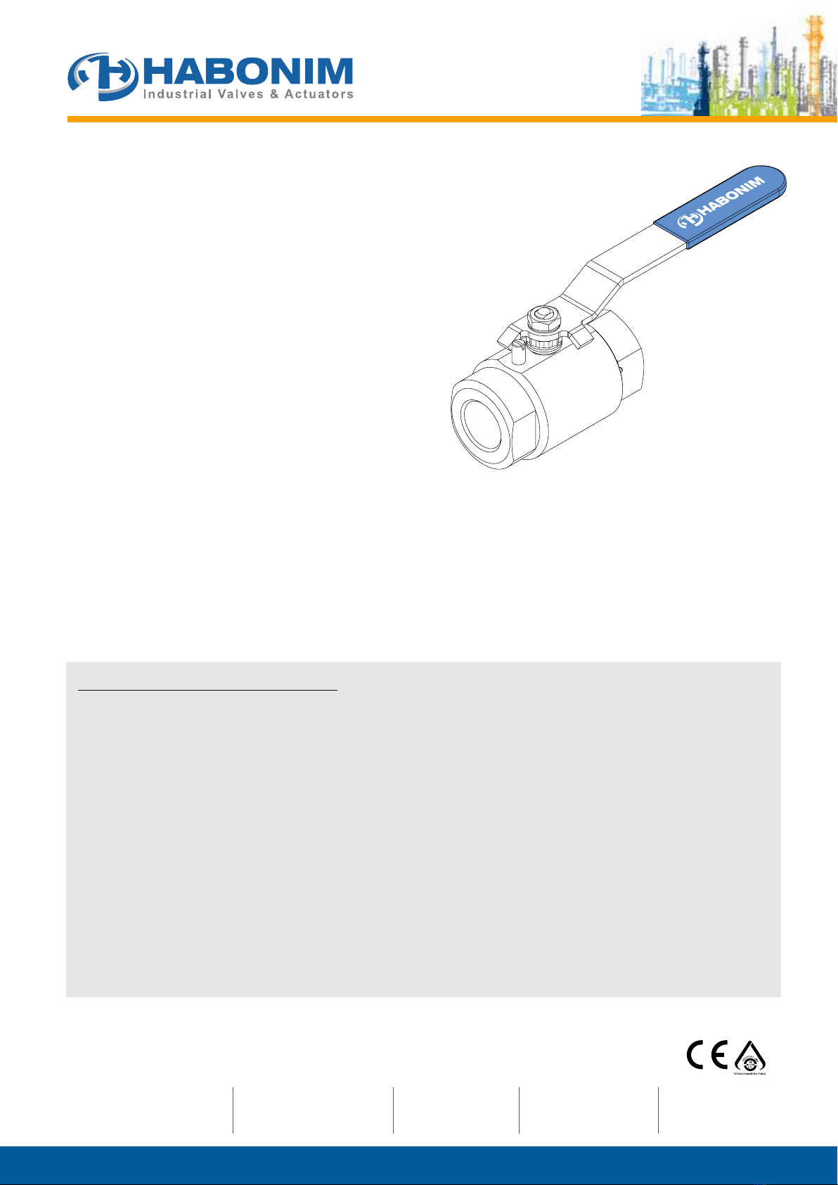
HABONIM AFH24 Owner's manual

Installation, Operating & Maintenance
2-Piece High Pressure Ball Valves
Series included:
H24, AH24X, AFH24
Sizes included:
½” – 1½” (DN15-DN40)
WARNINGS & SAFETY INSTRUCTIONS
Habonim cannot anticipate all of the situations a user may encounter while installing and using Habonim valves. The user MUST
know and follow all applicable industry specifications on the safe installation and use of these valves. Misapplication of the
product may result in injuries or property damage. Refer to Habonim product catalogues, product brochures and installation,
operating and maintenance manuals for additional product safety information or contact Habonim.
1. Keep hands and objects away from the valve ports at all times. Actuated valves could be accidentally operated, resulting in
serious injury or valve damage.
2. Before removing a valve from the line, always make sure the line has been depressurized and drained. Cycle the valve a few
times to relieve any pressure that could be trapped in the body cavity.
3. Utmost caution must be taken when handling a valve that has toxic, corrosive, flammable or a contaminant nature media
flowing through its pipeline. The following safety precautions are recommended when dismantling valves with hazardous
media:
a. Wear eye shield, protective headgear, clothing, gloves and footwear.
b. Have available running water.
c. Have a suitable fire extinguisher when media is flammable.
4. Do not try to operate a valve that exhibits any sign of leakage. Isolate the valve and either repair or replace it.
5. Do not use or substitute non Habonim components or parts in Habonim valves and assemblies.
1. GENERAL
This Installation, Operating & Maintenance manual present the instructions required for safe use of Habonim 2-piece High Pressure,
reduced bore ball valves type H24 series. Before using any of these valves, read the entire IOM carefully and make sure you understand
everything. Where in doubt, please consult with Habonim engineering team.
Inspired By Challenge
Habonim ISRAEL
Tel: +972-4-6914911 / 6914903
Fax: +972-4-6914935
Habonim USA
Toll Free Phone: 1-866-261-8400
Toll Free Fax: 1-866-243-9959
Habonim China
Tel: + 86 21 64453190 *146
Fax: + 86 21 64453191
Habonim UK
Tel: +44-1633-484554
Fax: +44-1633-482252
Habonim Australia
Tel: +61 3 9556 5428
I-H24-12/15

Flanged Ball Valves
2
H24 Series
2. SIL
Under normal operating conditions the Habonim valve should be
inspected for proper functioning and signs of deterioration every
50,000 cycles or 6 months (whichever comes rst). Under severe
operating conditions inspection should be more frequently; detected
defects should be repaired promptly.
Severe operating conditions can be dened as:
• Application temperature less than -20 deg C
• Application temperature higher than +230 deg C
• Flow velocity higher than 5 m/sec for liquids, and 200 m/sec
for gaseous
• Acidic media PH < 5 or alkaline media PH > 9
• Differential pressure above 70bar
Habonim recommend a proof test interval of 12 months; in case of
Fail to Open ESD system a partial stroke is acceptable to conrm
that the installation is functioning properly.
For ESD systems with a Fail-To-Close demand, it is necessary to
plan a system shut-down; de-energize the system and inspect the
valve turning to its fully closed position.
It is essential to log-in the following parameters on site QA records
as a proof for preserving SIL capabilities: date, hour, name and
signature of the responsible engineer, air pressure on site, time to
close the valve, time to open the valve.
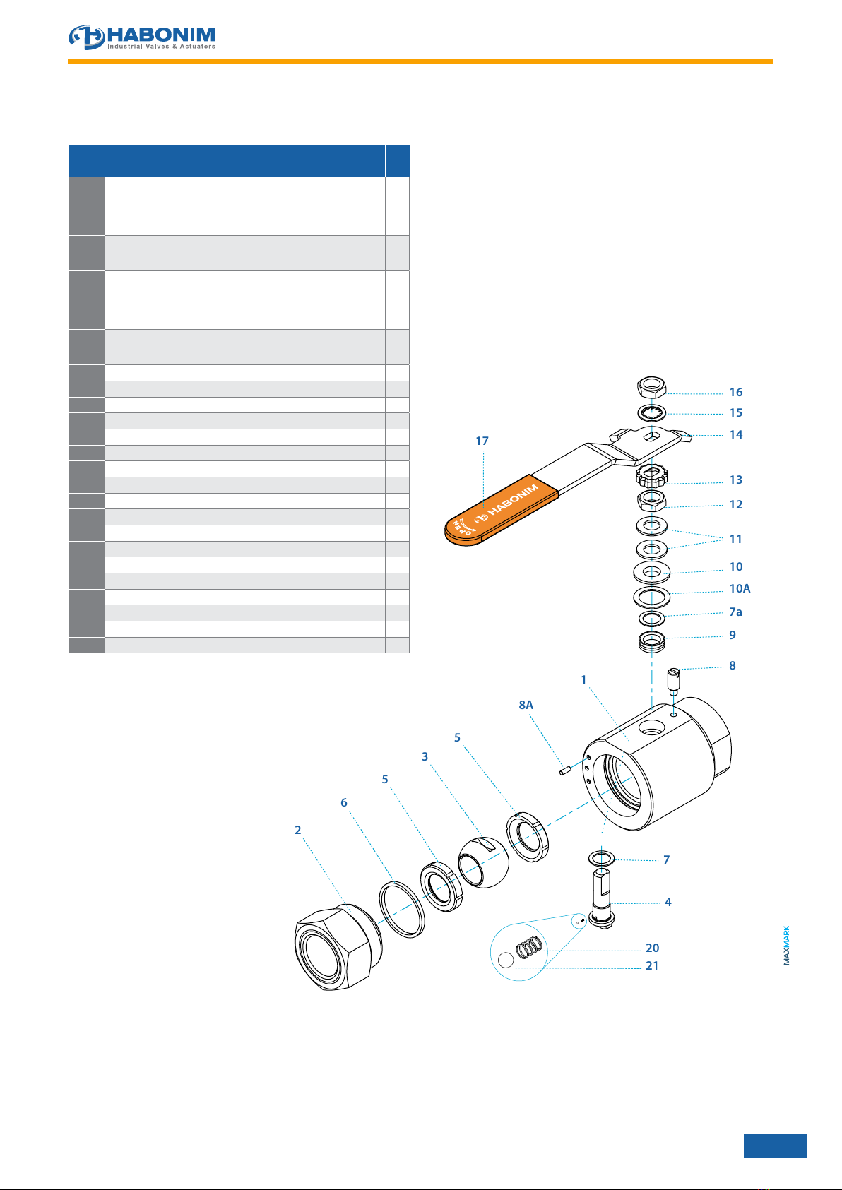
Habonim recommend valve full maintenance operation every
500,000 cycles or 4 years, whichever comes rst (refer to para. 7 in
this IOM for maintenance instructions). The combined corrosion and
erosion allowance for the valve body wall thickness is 1 mm. When
this allowance has been eroded or corroded, mechanically removed
or otherwise, the valve should no longer be used. Inspect the valve
wall thickness every time the valve is maintained. Refer to Habonim
Corrosion Data Chart T-614 to determine the corrosion rate for your
application.
The estimated mean time to repair (MTTR) a valve, i.e. time net
(line draining or cooling down time excluded from the valve MTTR)
of replacing old valve with a new one is 60 minutes. Maintenance
team must read and understand the Habonim product IOM before
starting the operation. In case of a doubt please consult the Habonim
engineering team.
When a valve has been repaired or any maintenance is performed,
check the valve for proper function (proof testing). Any failures
affecting functional safety should be reported to the Habonim factory.
Client should consult the Habonim factory in order to obtain the
product assessment, FMEDA report, and other associated statistical
data to satisfy SIL level.
3. LIMITATIONS
The correct selection of materials of construction, seats and seals,
internal valve components and pressure/temperature ratings
determines the safe use of the valves and the particular performance
requirements for the application. This information can be found on
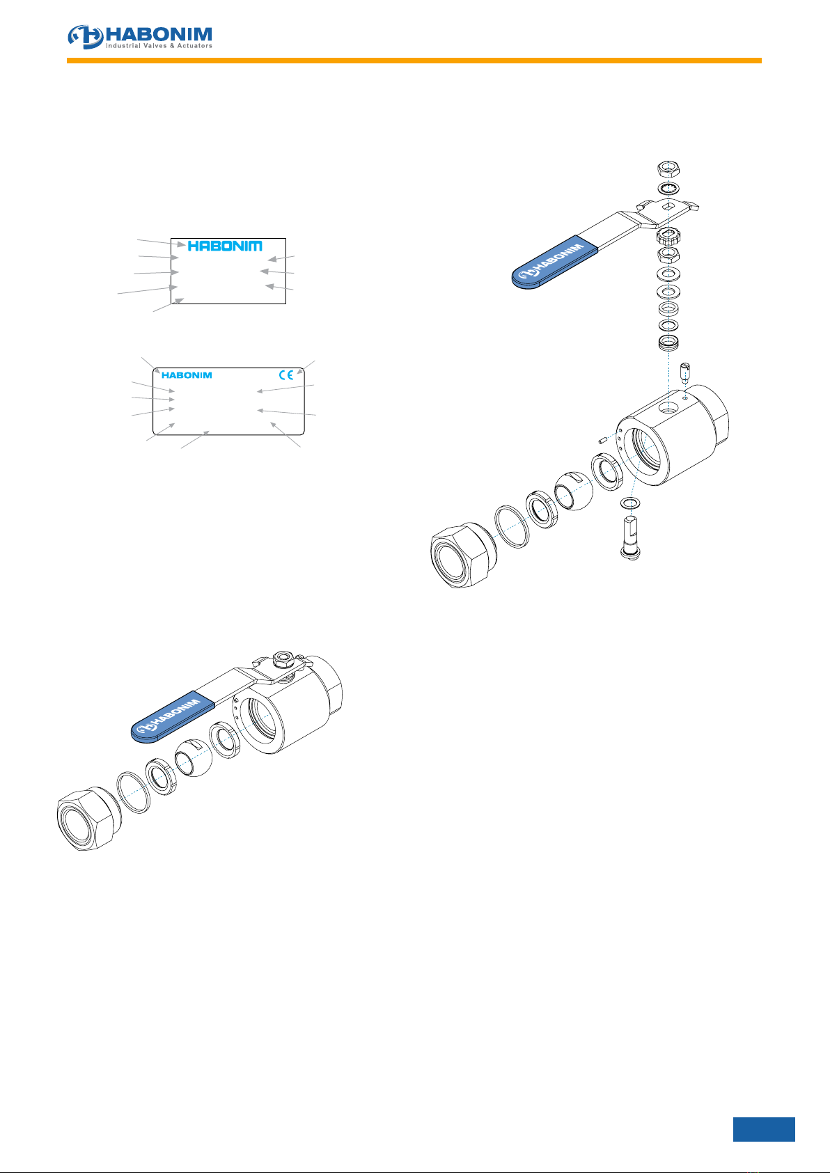
the nameplate welded to the valve body.
As the extent of applications that these valves can be used in, is
large, it is not possible to cover all installation and maintenance
instructions for service of the valves. It is the user’s responsibility
to use the valves as recommended and in accordance with the
pressure and temperature limits as stated in this manual. Where in
doubt, please consult with Habonim.
Any unstable uid or gas should be identied by its manufacturer
and must not be used with Habonim valves.
CAUTION:
The valves should be used in a well designed, adequately protected
system to ensure that external and internal pressure and
temperature limits do not exceed the valve limits.
Note: The valve body rating can be higher than the seat rating.
Valve surface temperature may become extremely hot or cold
due to ambient or operating conditions. Prevent any type of direct
contact with the valve that may cause harm or injury .Avoid direct
contact with the valve by wearing protective gloves.
The valves should be used in a well designed, adequately supported
piping system such that it will not be subjected to undue forces,
stresses or shock loads during service.
The valves are not designed to operate during or after earthquakes
or under fatigue conditions. It is the responsibility of the owner to
determine if fatigue conditions exist.
Do not allow dust layers to build up on the equipment.
The process fluid temperature shall not exceed the ignition
temperature of the dust.
4. STORAGE
Prior to storage, inspect the valve for shipping damage. Keep all
protective packaging, ange covers and end caps attached to the
valves during storage. It is recommended to keep the valves in a
clean and dry environment until ready for use.
Carbon Steel valves have a “black oxide” and oil dipped nish. This
nontoxic process is performed to retard rusting during storage. It is
not a substitute for paint or other means of protective coating to be
applied to the valve once installed.
Stainless steel valves have their natural nish and do not require
additional protection once installed.
5. LONG TERM STOREAGE
5.1. It is advisable to store the valves in waterproof conditions.
Ball valves should be protected to safeguard against humidity,
moisture, dust, dirt, sand, mud, salt spray, and sea water.
5.2. Manual ball valves must remain in the open position during
the period of storage.
5.3. Actuated valves (fail to close position) remain in closed
position during this time.
5.4. Valves may be stored as shipped, provided the above storage
location and equipment orientation instructions are followed
5.5. In order to prevent damage, protective covers on valve ends
should not be removed until immediately prior to installation.
5.6. Visual inspection should be performed on a semi-annual
basis and results recorded.
5.7. If the actuated valve (fail to close position) is planned for long
storage after dispatch it will be necessary to operate once in
6 months for fully open/close position.
5.8. Ball valves should be operated for at least two complete
cycles before installing or returning to storage.

Flanged Ball Valves
3
H24 Series
6. OPERATING INSTRUCTIONS
Habonim Valves provide tight shut off when used under normal
conditions and in accordance with Habonim’s published pressure/
temperature chart. If these valves are used in a partially open
(throttled) position, seat life may be reduced. Consult with Habonim
for the proper seat material selection.
Valve operation works by operating the valve handle 90° turn anti-
clockwise to open, and 90° turn clockwise to close. On manually
operated valves the valve is open when the handle or stem ats are
parallel with the pipeline and closed when the handle or stem ats
are perpendicular to the pipeline.
All standard valves are bidirectional and as such, can be installed
for ow in either direction. Valves which are unidirectional will have
a ow direction arrow welded to the body and separate assembly
instructions.
A silicone-based lubricant is applied to assist valve break in. The
lubricant, if unacceptable, may be removed by a solvent wash.
If a shut-off valve is installed for end of line service, it must be
ensured that it is closed with a blind end connection and the valve is
secured against being opened unintentionally.
WARNING: Never look into the valve bore while the valve is in a
owline. Pressure and uids could escape from the valve causing
bodily injury.
To prevent leakage, malfunctions resulting from internal wear or seal
degradation, the user must establish a preventive maintenance and
inspection program. This program must include:
a. Inspection of parts to detect loss of wall thickness which
may result in decreased pressure capacity (see para. 2 for
acceptable reduction of wall thickness).
b. Routine replacement of seals and inspection for proper
operation (See para. 7 for maintenance instructions).
Valve operating torques as published in the Habonim literature are
the normal expected maximum break-away torques. These torques
have been conrmed by laboratory testing of each valve under
controlled conditions. Highly viscous or abrasive media, frequency
of operation and temperature uctuations could cause an increase
in valve torque.
7. INSTALLATION
The installation procedure for ball valves is critical to ensuring both
long life and satisfactory performance. Valves stored on site awaiting
installation should be kept in their original packing, in dry conditions,
where damage will not occur (see para. 4). Before carrying out the
installation, it is important to follow the basic procedures described
below:
7.1 General
7.1.1. Carefully unpack the valve and check valve nameplate for
identication of materials (see Figure 2).
7.1.2. Remove any special packing materials, which were used for
packing.
7.1.3. Check the valve for any ow direction indication marks.
Appropriate care must be taken, to install the valve for proper
ow orientation.
7.1.4. Inspect the valve interior through the end ports to determine
it is clean and free from foreign matter according to ASME
G93-03E1.
7.1.5. Cycle the valve and inspect any functionally signicant
features.
7.1.6. Read all the literature and note any special warning tags or
plates attached to the valve.
7.1.7. Before installation check to insure the ball is in the fully open
position in order to prevent possible damage to the ball
and seats. The valve performance depends on its original
conditions. At any stage do not leave the valve in the partially
open position.
7.2 Threaded End Valves
7.2.1. Valves with threaded ends should be treated as a single unit
and should not be dismantled when installing to pipeline.
7.2.2. Before installing the valves, make sure that the threads on
the mating pipe are free from excessive grit, dirt or burrs.
7.2.3. When tightening the valve, apply a pipe wrench or spanner
to the end connector closest to the pipe being worked, using
standard piping practices.
7.2.4. Use appropriate joining sealants material in correct quantities.
7.2.5. If “back-welding” is required on threaded end valves, refer
to the instructions for Weld End valves or to the “Habonim
Welding Instructions” bulletin.
8. MAINTENANCE
HABONIM valves have a long and trouble free life, and
maintenance is seldom required. When maintenance is necessary,
valves can be refurbished on site.
To extend valve performance and reduce possible plant problems,
the following procedures should be followed:
8.1. If leakage at the stem is noted, tighten the gland nut about
a 1⁄6-turn as a routine maintenance procedure. This will
compensate for any wear or settling of the gland packing.
8.2. Caution: Excessive tightening of the stem nut can result in
accelerated seal wear and high valve operating torque.
8.3. If the valve is removed from the line and disassembled,
replacement of all seats and seals is recommended using
the appropriate Habonim Repair kit. Examine all metallic
sealing surfaces such as ball, stem, and the surfaces on the
end connectors that contact the seats for wear, corrosion or
damage.
8.4. Only Habonim’s authorized spare parts should be used.
Repair kits from Habonim consist of the following:
2 x seat ring
1 x stem packing
1 x stem thrust seal
1 x body seals
1 x Safety Pin
8.5. In addition to repair kits, other spare parts available from
Habonim are: valve balls, stems, glands, bolts, screws and
nuts. Should additional parts be required, it is recommended
that the complete valve be replaced.
8.6. When ordering repair kits, please provide the valve size and
full gure number code and series.

Flanged Ball Valves
4
H24 Series
9. DISASSEMBLY
The following instructions are for off-line disassembly of
valves sizes 1⁄2” to 1 1⁄2”
9.1. Cycle the valve with the line pressure fully relieved before
attempting to remove the valve from the pipeline, to insure
pressure has also been discharged from the valve cavity.
9.2. Bring the valve handle to the open position.
9.3. Remove the valve from the pipeline using appropriate
wrench (see table 2).
9.4. Inspect the valve interior through the end ports to determine
it is clean and free from foreign matter.
9.5. Clamp the valve in a vice, pull the safety pin out and release
the end connector.
9.6. Remove and discard the body seal and seats. Be careful not
to damage the sealing surfaces.
9.7. Turn the handle to the closed position to enable removal of
the ball. Carefully slide the ball out .Set the ball aside in clean
secure area for reuse.
9.8. Remove the wrench nut, serrated washer, handle, locking
clip, gland nut, disk springs and gland. Place all components
removed, in clean secure area.
9.9. Push the stem down into the body and remove it. Discard
the stem thrust ring and packing, care taken not to scratch or
nick the packing bore area of the body. Clean the stem and
packing bore area.
9.10. Remove and discard the second seat.
10. ASSEMBLY
The following instructions are for off-line assembly of valves
sizes 1⁄2” to 1 1⁄2”
10.1. Insert one new seat ring into the valve cavity with its round
prole facing up.
10.2. Lubricate the new stem thrust ring and packing, with
appropriate lubricant (Molycote 33 - thin smear). Place the
stem thrust ring on the stem.
10.3. Insert the stem horizontally into the center body with the
threaded side rst and carefully guide it up through the stem
bore.
10.4. Holding the stem up insert the new packing over the stem and
into the stem bore. Place the follower and two disk springs
(face to face) onto the stem.
10.5. Thread the stem nut onto the stem. Tighten the stem nut to
the torque gures (table 1).
10.6. Place the locking clip on the stem nut by adjusting the
orientation of the nut (in the clockwise direction).
10.7. Place the handle, serrated washer and thread the handle nut
on the stem. Holding the handle tighten the handle nut tight.
10.8. Bring the handle to the closed position and insert the ball in
the valve cavity until the stem tounge is engaged to the ball
slot and the ball is nested in the seat.
10.9. Place the new body seal and seat ring into the valve body.
10.10.Screw back the end connector using the proper wrench and
tighten according to table 2.
10.11. Place the safety pin in its hole. Use an hammer to insert the
pin inside. Refer to the installation instructions in section 5 of
this manual to complete the valve assembly to the line.
TABLE 1
Stem Nut Tightening Torque
Full Bore Nut Thread
* PTFE Gland
Packing Graphite Seal Hermetix™
Nm in.lb Nm in.lb Nm in.lb
½”- ¾” ⁄” - 24 UNF 4 35 6 53 6 53
¾” ⁄” - 24 UNF 4 35 6 53 6 53
1” ⁄” - 20 UNF 9 80 11 97 11 97
1¼” ⁄” - 20 UNF 9 80 11 97 11 97
1½” ⁄” - 18 UNF 13 115 16 140 15 133
* These torque gures are applicable on other stem seal materials
such as glass lled PTFE, UHMWPE and TFM.
IMPORTANT:
An excessively tightened stem nut can cause excessive packing wear
and increase stem torque.
TABLE 2
End Connector Tightening Torque
Size Nut
Thread
Tightening
Torque
Hexagon
Dimensions
Nm in.lb mm inch
½” 1 1⁄8” – 18 UNEF-2A 120 1060 30 1.18
¾” 1 7⁄16”– 18 UNEF-2A 150 1330 40 1.57
1” 1 7⁄8”– 16 UN-2A 180 1600 50 1.97
1 ¼” 2 1⁄4”– 20 UN-2A 210 1860 60 2.36
1 ½” 25⁄8” – 16 UN-2A 240 2100 70 2.75

Flanged Ball Valves
5
H24 Series
FIGURE 1
Valve Marking and Labeling
All valves marking is on a nameplate which is spot welded to the
valve body. Valves for the European market and above 1” carry the
CE mark with the information required by the PED.
ATTENTION:
Prior to servicing the valve, bring it to the open position
making sure to release line pressure and drain all trapped
media from the valve cavity.
FIGURE 2
Valve swing out position and maintenance
BODY BALL
SEAT
PRES.SIZE
**** ****
**** ****
** ***
******************
Habonim logo
Body material
Seat material
Valve size
Valve description
Ball material
Work order
Max. pressure
Step 1 – Slide out and center Section maintenance
Step 2 – Stem maintenance
INDUSTRIAL VALVES & ACTUATORS LTD
KFAR HANASSI, 1230500 IL
BODY
BALL
SEAT
BAR @ °C
1155
Habonim logo
Body material
Max. pressure @
Min. temperature Min. pressure @
Max. temperature
Valve description
CE mark
Ball material
Seat material
Valve size
Year manufacture
DN
P.O.
YR
BAR @ °C

Flanged Ball Valves
6
H24 Series
H24 - 1⁄2” to 1 1⁄2” (DN15 to DN40)
In accordance with our policy to strive for continuous improvement of the product, we reserve the right to alter the dimensions,
technical data and information included in this IOM when required.
9
8
7a
16
11
12
13
10
14
15
10A
7
4
2
3
6
5
5
1
8A
20
21
17
ø W
H
DC
B
A
S
ø Ball port
Y
Preparation
for actuation
M
N Thread
P
P
Stem flats
show valve
ball position
¼"-¾"
without nut
1" - 1½"
with nut
Item Description Material specification Qty.
1
Body
S.St. A479 316/316L, C.St. A350 LF2,
B473 N08020 (Alloy 20), B164 N04400 (Monel
400), B574 N06022 (Alloy C22), B574 N10276
(Alloy C276), A479 S31254 (254 SMO), A479
S31803 (Duplex), A479 S32750 (Super Duplex)
1
2
End
A479 316/316L, A350 LF2
B473 N08020, B164 N04400, B574 N06022, B574
N10276, A479 S31254, A479 S31803, A479 S32750
1
3
Ball
S.St for 1/2" and 3/4" valves: A564 Gr.630 H1150D
17-4PH, S.St for 1" and up valves: A351 CF8M,
A479 316/316L, B473 N08020 , B164 N04400, B574
N06022, B574 N10276, A479 S31254, A479 S31803,
A479 S32750, B637 UNS-N07718 (Inconel 718)
1
4
Stem
A564 Gr.630 H1150D 17-4PH, B164 N04400,
B574 N06022, A479 S31803, A479 S32750, B637
UNS-N07718 (Inconel 718)
1
5*
Seat
PVDF, DELRIN, PEEK, CF PEEK, PCTFE (KEL-F)
2
6*
Body seal
PTFE, Graphite, NBR, Viton
1
7*
Stem thrust seal
PEEK, CF PEEK, PCTFE (KEL-F), TFM
(2)
, CF PTFE
(2)
1
7a**
Anti-abrasion ring
PEEK, CF PEEK, PCTFE (KEL-F), TFM
(2)
, CF PTFE
(2)
1
8
Stop pin
A582 303
1
9*
Stem seal
CF PTFE, TFM, Graphite
(2)
1
10
Follower
B783 316L
1
10A*
Slide bearing
TF316
1
11
Disc spring
A693 631 17-7PH
2
12
Stem nut
A194 8M, EN3506-2 A4-80
1
13
Locking clip
A164 8, 8A
1
14
Handle
C.St. A29 G10200 Zinc plate, S.St. A240 430
1
15
Serrated washer
A194 6
1
16
Handle nut
A194 8M, EN3506-2 A4-80
1
17 Sleeve
PVC
1
20 Anti static spring
A313 302
1
21
Anti-static plunger
A479 304
1
23
Tag (not shown)
A167 304
1
* Repair kit components
** Only with HermetiX™ stem seal. Does not supplied in
1
/
2
" and
3
/
4
" valves
This manual suits for next models
2
Table of contents
Other HABONIM Control Unit manuals
Popular Control Unit manuals by other brands

Elkron
Elkron MP 200 Installation and maintenance manual

CKD
CKD M3GA/B R Series instruction manual

Nor-Cal Products
Nor-Cal Products Intellisys TBV-D Operator's manual

VeEX
VeEX RXT-6400 user manual

Emerson
Emerson Bettis XTE3000 Installation, operation and maintenance manual

Rittal
Rittal 7320.790 Assembly and operating instructions