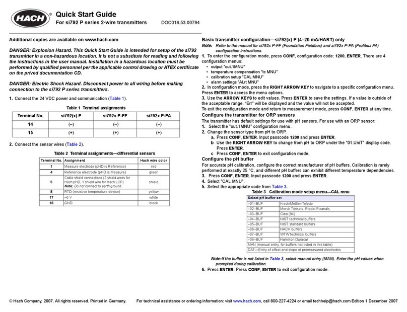
Hach si792 T User manual

DOC026.52.00796
si792(x) E—Hach GLI 3700 series
si792(x) T—7MA2200 and 8398 series
Inductive Conductivity
2-Wire Transmitter
USER MANUAL
December 2007, Edition 1
© HACH Company, 2007. All rights reserved. Printed in Germany


1
Table of Contents
Section 1 Specifications ......................................................... 5
Section 2 General information ........................................... 11
2.1 Safety information .................................................................... 11
2.1.1 Use of hazard information ................................................. 11
2.1.2 Precautionary labels.......................................................... 11
2.2 General product information..................................................... 13
2.2.1 Product overview............................................................... 13
2.2.2 FDA 21 CFR part 11 compliance (HART only) ................. 14
2.2.2.1 Electronic signatures for si792(x) E/T transmitters ....14
2.2.2.2 Audit trail for si792(x) E/T transmitters.......................14
Section 3 Installation .............................................................. 15
3.1 Hazardous location installation................................................. 16
3.1.1 ATEX safety information ................................................... 16
3.2 Unpacking the transmitter ........................................................17
3.3 Mechanical installation ............................................................. 18
3.3.1 Transmitter assembly ........................................................ 18
3.3.2 Mounting ........................................................................... 18
3.3.2.1 Wall mount ................................................................. 18
3.3.2.2 Panel or pipe mount (optional) ................................... 18
3.4 Wiring Safety Information......................................................... 20
3.5 Electrical installation................................................................. 21
3.5.1 Wire preparation................................................................ 21
3.5.2 Power and communication connections............................ 23
3.5.2.1 si792(x) E/T (4-20 mA/HART) wiring.......................... 24
3.5.2.2 si792x E/T-FF and si792x E/T-PA wiring ................... 25
3.5.3 Sensor wire connections ................................................... 25
3.5.3.1 Hach GLI 3700 series sensor wiring—si792(x) E ...... 26
3.5.3.2 7MA2200 series sensor wiring—si792(x) T ............... 27
3.5.3.3 8398 series sensor wiring—si792(x) T....................... 28
3.6 HART communication connection ............................................ 29

Table of Contents
2
Section 4 Interface and navigation ..................................31
4.1 si792(x) E/T (4–20 mA/HART) interface...................................31
4.2 si792x E/T-FF and si792x E/T-PA interface .............................32
4.3 Display......................................................................................33
Section 5 Operation—4–20 mA/HART............................35
5.1 Measure mode ......................................................................... 35
5.2 Configuration ............................................................................ 35
5.2.1 Current output configuration..............................................36
5.2.1.1 Time constant of output filter......................................39
5.2.1.2 Output signal during errors.........................................39
5.2.1.3 Output signal during HOLD ........................................ 40
5.2.2 Temperature compensation configuration.........................41
5.2.3 Alarm settings....................................................................42
Section 6 Operation—Foundation Fieldbus................43
6.1 Configuration ............................................................................ 43
6.1.1 Configuration steps ...........................................................43
6.1.2 Configuration menu........................................................... 44
6.2 Foundation Fieldbus communication........................................47
6.2.1 Standard resource block (RB)...........................................47
6.2.2 Standard analog input block (AI).......................................50
6.2.2.1 Operating modes........................................................50
6.2.2.2 Set the parameter and units.......................................50
6.2.2.3 Data processing ......................................................... 51
6.2.2.4 Alarms ........................................................................ 51
6.2.2.5 Bus parameters for the analog input block.................52
6.2.2.6 Cyclic measured value status.....................................55
6.2.2.7 Measured value limits—limit bits................................55
6.2.3 Transducer block...............................................................56
6.2.4 Calibration via Foundation Fieldbus..................................63
Section 7 Operation—Profibus PA................................... 65
7.1 Configuration ............................................................................ 65
7.1.1 Configuration steps ...........................................................65

Table of Contents
3
7.1.2 Configuration menu........................................................... 66
7.2 Profibus PA communication ..................................................... 67
Section 8 Calibration .............................................................. 71
8.1 Calibration ................................................................................ 71
8.1.1 Enter cell constant............................................................. 72
8.1.2 Calibration with a calibration solution................................73
8.1.3 Calibration by comparison/grab sample............................74
8.1.4 Zero calibration—air.......................................................... 75
8.1.5 Zero calibration—calibration solution ................................ 75
8.2 Temperature sensor adjustment .............................................. 76
Section 9 Maintenance........................................................... 77
9.1 Cleaning the instrument ........................................................... 77
9.2 Sensor maintenance ................................................................ 77
Section 10 Troubleshooting ................................................ 79
10.1 Sensoface .............................................................................. 79
10.2 Sensocheck............................................................................ 79
10.3 Error codes............................................................................. 80
10.4 Diagnostic tests ...................................................................... 82
Section 11 Replacement parts............................................ 85
11.1 si792 transmitter versions ...................................................... 85
11.2 Accessories ............................................................................ 85
11.3 Replacement parts ................................................................. 85
Section 12 Contact information......................................... 87
Section 13 Limited warranty ............................................... 90
Appendix A Calibration solutions .................................... 93
Appendix B Concentration curves................................... 97
B.1 Concentration measurement ranges........................................ 97
B.2 Sodium chloride solution -01- NaCl ......................................... 99
B.3 Hydrochloric acid -02- HCl..................................................... 100
B.4 Sodium hydroxide solution -03- NaOH .................................. 101
B.5 Sulfuric acid -04- H2SO4. ....................................................... 102

Table of Contents
4
B.6 Nitric acid -05- HNO3. ............................................................103
Appendix C Passcode editor ............................................105
Appendix D ATEX safety instructions..........................107
Index...............................................................................................111

5
Section 1 Specifications
Specifications are subject to change without notice.
Transmitter
Composition PBT (polybutylene terephthalate)
Display LCD
Fittings
3 knockouts for M20 x 1.5 strain reliefs
2 knockouts for ½ inch NPT or rigid
metallic conduit
Power requirements—HART 14–30 VDC (30 VDC maximum)
Power requirements—FF and Profibus
PA
FISCO bus supply: 9 to 17.5 VDC
Linear barrier: 9 to 24 VDC
Loop current—HART 4–20 mA floating;
3.80–22.00 mA specifiable
Current consumption—FF and Profibus
PA <13.2mA
Maximum current in case of fault
(FDE)—FF and Profibus PA <17.6mA
Measurement error2<0.3% of current value + 0.05 mA

Specifications
6
Certification (may not apply to all
sensors. Refer to the control drawing or
listing for certification information for
the sensor that is used).
US:
si792 E/T
FM Listed for:
Class I, Division 2
si792x E/T; si792x E/T-FF;
si792x E/T-PA
FM Listed for:
Class I, Division 1, Groups A, B, C, D
Class II, Division 1, Groups E, F
Class III, Division 1
Class I, Zone 0, AEx ia, Group IIC T4
Enclosure: Type 2
Canada:
si792 E/T
CSA Certified to:
Class I, Division 2
si792x E/T CSA Certified and
si792x E/T-FF; si792x E/T-PA
cFMus Certified to:
Class I, Division 1, Groups A, B, C, D
Class I, Division 2, Groups A, B, C, D
Sensor: Class I, Zone 0, Group IIC
Transmitter: Class I, Zone 1, Group IIC
Enclosure: Type 2
EU:
si792x E/T; si792x E/T-FF;
si792x E/T-PA:
CE Marked to:
EMC Directive 2004/108/EC
ATEX Directive 94/9/EC
ATEX: II 2 (1) G EEx ib (ia) IIC T6
Enclosure: IP65
Output averaging time constant (HART) 0–120 seconds
Storage temperature –20 to 70 °C (–4 to 158 °F)
Operating temperature –20 to 55 °C (–4 to 131 °F)
Weight Approximately 1 kg

Specifications
7
Data retention Parameters and calibration data
> 10 years (EEPROM)
Passcodes
Modifiable according to FDA 21 CFR
Part 11 “Electronic Signatures”
(HART only)
Sensocheck
Monitoring of primary coil and its lines
for short circuit and of secondary and
its lines for open circuit
Sensor monitor
Direct display of measured values from
sensor for validation (resistance/
temperature)
Communication
HART communication
Digital communication by FSK
modulation of loop current, reading of
device identification, measured values,
status and messages, reading and
writing of parameters, start of product
calibration, signaling of configuration
changes according to FDA 21 CFR
Part 11.
Foundation Fieldbus (FF_H1)
Bus-powered device with constant
current consumption. Cyclic and acyclic
data exchange. 1 resource block,
1 transducer block, 3 analog input
function blocks (switchable:
conductivity, concentration, salinity,
temperature, cell constant)
Execution time: 50 ms
Certified to ITK 4.6
Physical interface: to IEC 1158-2
Address range: 017 to 246

Specifications
8
Profibus-PA (DPV1)
Bus-powered device with constant
current consumption. Cyclic and acyclic
data exchange. Physical block,
2 analog input function blocks,
2 discrete input blocks, logbook block,
alarm block.
PNO directive: PROFIBUS-PA,
Profile for Process Control Devices,
Version 3.0
Physical interface: MBP-IS
(Manchester Bus Powered-Intrinsically
Safe) to IEC 1158-2 (DIN-EN 61158-2)
Connection: via segment coupler to
SPC, PC, PCS
Address range: 1 to 126
Conductivity input
Electrodeless conductivity sensors,
ranges
7MA2200 series
8398 series
Hach 3700 series
Conductivity 0.00–1999 mS/cm
Concentration 0–100% by weight
Salinity 0.0–45 ‰ (0–35 °C)
Range, conductivity
0.000–9.999 mS/cm
00.00–99.99 mS/cm
000.0–999.9 mS/cm
0–1999 mS/m
0.000–9.999 S/m
00.00–99.99 S/m
Range, concentration 0.00–100.0% by weight
Range, salinity 0.0–45 ‰ (0–35 °C)
Measurement error < 1% measured value + 0.02 mS/cm
Temperature input
Sensor Pt100/PT1000/NTC 30 kΩ/NTC 100 kΩ
2-wire connection

Specifications
9
Range, Pt100/Pt1000 –20.0 to 200.0 °C (–4 to 392 °F)
Range, NTC 30 kΩ–20.0 to 150.0 °C (–4 to 302 °F)
Range, NTC 100 kΩ–20.0 to 130.0 °C (–4 to 266 °F)
Adjustment range 10 K
Resolution 0.1 °C; 0.1 °F
Measurement error1,2< 0.5 K
(< 1 K for Pt100;<1 K for NTC >100 °C)
1(± 1 count plus sensor error)
2IEC 746 Part 1, at nominal operating conditions

Specifications
10

11
Section 2 General information
2.1 Safety information
Please read this entire manual before unpacking, setting up, or
operating this equipment. Pay attention to all danger and caution
statements. Failure to do so could result in serious injury to the operator
or damage to the equipment.
To ensure that the protection provided by this equipment is not
impaired, do not use or install this equipment in any manner other than
that specified in this manual.
2.1.1 Use of hazard information
DANGER
Indicates a potentially or imminently hazardous situation which, if
not avoided, could result in death or serious injury.
CAUTION
Indicates a potentially hazardous situation that may result in
minor or moderate injury.
Important Note: Information that requires special emphasis.
Note: Information that supplements points in the main text.
2.1.2 Precautionary labels
Read all labels and tags attached to the instrument. Personal injury or
damage to the instrument could occur if not observed. A symbol, if
noted on the instrument, will be included with a danger or caution
statement in the manual.
This symbol, if noted on the instrument, references the instruction
manual for operation and/or safety information.

General information
12
Electrical equipment marked with this symbol may not be disposed of
in European public disposal systems after 12 August of 2005. In
conformity with European local and national regulations (EU
Directive 2002/96/EC), European electrical equipment users must
now return old or end-of life equipment to the Producer for disposal
at no charge to the user.
Note: For return for recycling, please contact the equipment
producer or supplier for instructions on how to return end-of-life
equipment, producer-supplied electrical accessories, and all auxiliary
items for proper disposal.
This symbol, when noted on a product enclosure or barrier, indicates
that a risk of electrical shock and/or electrocution exists.
This symbol, when noted on the product, identifies the location of the
connection for Protective Earth (ground).
This symbol, when noted on the product, identifies the location of a
fuse or current limiting device.
This symbol, when noted on the product, identifies a risk of chemical
harm and indicates that only individuals qualified and trained to work
with chemicals should handle chemicals or perform maintenance on
chemical delivery systems associated with the equipment.
This symbol, when noted on the product, identifies the presence of a
strong corrosive or other hazardous substance and a risk of chemical
harm. Only individuals qualified and trained to work with chemicals
should handle chemicals or perform maintenance on chemical
delivery systems associated with the equipment.
This symbol, when noted on the product, indicated the presence of
devices sensitive to Electro-static Discharge (ESD) and indicated
that care must be taken to prevent damage with the equipment.
This symbol, when noted on the product, identifies the presence of
noxious substances and a risk of chemical harm. Only individuals
qualified and trained to work with chemicals should handle chemicals
or perform maintenance on chemical delivery systems associated
with the equipment.

General information
13
2.2 General product information
DANGER
Explosion hazard. The Hach GLI 3700 series sensors can only be
used with the si792(x) E transmitter.
2.2.1 Product overview
The si792 T, si792x T, si792 E and si792x E transmitters are used for
measurement of electrical conductivity and temperature in liquids.
Fields of application are: biotechnology, chemical industry,
environment, food processing and water/waste-water treatment.
The E and the T models differ only in the types of sensors that can be
used with the transmitter. The operation of each version is identical.
This user manual refers to both versions as E/T.
The molded transmitter enclosure can be attached to a panel, wall, post
or pipe railing. The optional hood (see Accessories on page 85)
provides protection against direct weather exposure and mechanical
damage.
Three communication options are available for the si792 transmitter:
• 4–20 mA/HART—si792 E, si792 T, si792x E and si792x T (noted as
si792(x) E/T)
• Foundation Fieldbus—si792x E-FF and si792x T-FF
• Profibus PA—si792x E-PA and si792x T-PA
This user manual includes instructions for all three protocols.
Important Note: An ‘x’ in the model number is an indication of an
intrinsically safe (IS) instrument.
The instruments are compatible with different sensor types. See si792
transmitter versions on page 85 for a list of instrument versions.

General information
14
2.2.2 FDA 21 CFR part 11 compliance (HART only)
In the directive “Title 21 Code of Federal Regulations, 21 CFR Part 11,
Electronic Records; Electronic Signatures“ the US American health
agency FDA (Food and Drug Administration) regulates the production
and processing of electronic documents for pharmaceutical
development and production. The features described in section 2.2.2.1
and section 2.2.2.2 make the transmitter compliant with the
requirements of FDA 21 CFR Part 11.
2.2.2.1 Electronic signatures for si792(x) E/T transmitters
Device functions are protected by passcode access, which prevents
unauthorized modification of device settings or manipulation of
measurement results. Passcodes may be used as electronic
signatures. Passcodes can be edited with the passcode editor
(Appendix C on page 105).
2.2.2.2 Audit trail for si792(x) E/T transmitters
The si792(x) transmitter can automatically track all changes to the
device settings. Each change is tagged with a Configuration Change
flag, which is documented using HART communication. Altered device
settings or parameters can be retrieved from the transmitter using
HART communication.

15
Section 3 Installation
DANGER
Explosion hazard. Trained personnel only must install or
commission the equipment.
DANGER
Explosion hazard. Never connect items to the transmitter that are
not specified on the control drawing. Do not connect or
disconnect any equipment unless power has been switched off or
the area is known to be non-hazardous.
DANGER
Explosion hazard. The safety of the transmitter may be impaired if
any of the following conditions have occurred:
• visible damage
• storage above 70 °C for prolonged periods
• exposure to severe transport stresses
• previous installation
• failure to operate properly
If any of these conditions have occurred, return the device to the
manufacturer for recertification.
The si792 and si792x transmitters differ in hazard classification. The
si792 transmitter is designed for non-hazardous or Class I, Division 2,
Groups A, B, C, D hazardous locations. The si792x transmitter is
designed for Class I, Division 1, Groups A, B, C, D hazardous locations.
Refer to the control drawing or listing applicable to the site location.
For outdoor installation, install a protective hood or sunshield
(see Accessories on page 85).
Installation of the si792x in an outdoor hazardous location per FM or
CSA control drawings requires a suitable enclosure and must follow
NEC guidelines. Refer to NEMA 250 to determine enclosure needs.

Installation
16
3.1 Hazardous location installation
Before installation, review the applicable Hazardous Location Control
Drawings or ATEX EC-Type Examination certificate and safety
information included with the instrument and on the provided
documentation CD. Follow all regulations specified for the installation
location.
Refer to the documentation CD for manuals provided in other
languages.
3.1.1 ATEX safety information
Refer to Appendix D for safety information on the use of the
electrodeless sensors.

Installation
17
3.2 Unpacking the transmitter
Check the shipment for transport damage and make sure all
components have been shipped complete. The package includes:
• Display module • Bag of hardware and fasteners
• Back enclosure • Test report and user manual
Figure 1 Instrument Components
1 Back enclosure 8 Strain relief (3x)
2 Optional conduit hardware 9 Filler plug (3x)
3 Conduit washer 10 Enclosure screw (4x)
4 Jumper (2x) 11 Display module
5 Cable tie (3x) 12 Hinge pin
6 Sealing insert 13 Hex nuts (5x)
7 Rubber reducer 14 Sealing plug (2x)

Installation
18
3.3 Mechanical installation
3.3.1 Transmitter assembly
Refer to Figure 1 and the following instructions to assemble the
transmitter.
1. Insert the strain relief fittings in the holes of the back enclosure and
secure with the hex nuts (Figure 2).
2. Insert the conduit hardware or plugs in the back enclosure and
secure with the hex nuts.
3. Attach the display module to the back enclosure using the hinge pin.
3.3.2 Mounting
Refer to the following sections to mount the transmitter on a wall, panel
or pipe.
3.3.2.1 Wall mount
1. Use a punch to open the two wall-mount holes in the back enclosure
(Figure 2).
2. Drill holes in the wall suitable for the user-supplied mounting bolts.
3. Attach the back enclosure to the wall using two customer-supplied
bolts.
4. Insert the clear plastic plugs into the mounting holes.
3.3.2.2 Panel or pipe mount (optional)
Refer to Figure 2 and the instructions supplied with the panel and pipe
mounting kits (see Accessories on page 85).
This manual suits for next models
1
Table of contents
Other Hach Transmitter manuals
Popular Transmitter manuals by other brands

Extron electronics
Extron electronics XTP T EU 202 Setup guide

WAREMA
WAREMA EWFS Wall-mounted transmitter plus Operating and installation instructions

Evikon
Evikon PluraSens E2611-CH4 user manual

Beyerdynamic
Beyerdynamic Unite TP quick start guide

JUMO
JUMO dTRANS p02 operating instructions

WIKA
WIKA D-20-9 operating instructions