Hach CAx440EX User manual

DOC273.99.80661
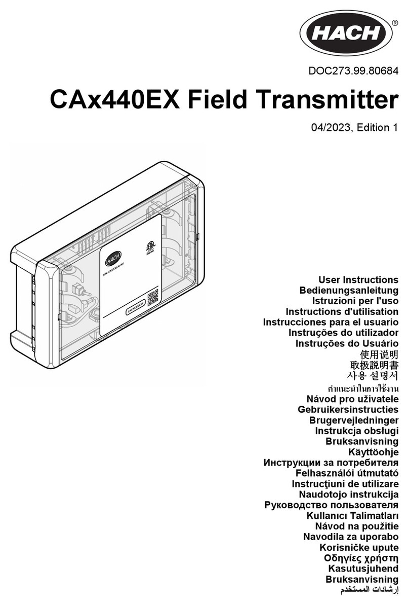
CAx440EX Field Transmitter
05/2023, Edition 2
User Instructions
Bedienungsanleitung
Istruzioni per l'uso
Instructions d'utilisation
Instrucciones para el usuario
Instruções do utilizador
Instruções do Usuário
使用说明
取扱説明書
사용 설명서
Návod pro uživatele
Gebruikersinstructies
Brugervejledninger
Instrukcja obsługi
Bruksanvisning
Käyttöohje
Инструкции за потребителя
Felhasználói útmutató
Instrucţiuni de utilizare
Naudotojo instrukcija
Руководство пользователя
Kullanıcı
Návod na použitie
Navodila za uporabo
Korisničke upute
Οδηγίες χρήστη
Kasutusjuhend
Bruksanvisning

Table of Contents
English..............................................................................................................................4
Deutsch.......................................................................................................................... 16
Italiano............................................................................................................................ 29
Français......................................................................................................................... 42
Español.......................................................................................................................... 55
Português...................................................................................................................... 68
Português...................................................................................................................... 81
中文................................................................................................................................. 94
日本語........................................................................................................................... 106
한국어........................................................................................................................... 118
.................................................................................................................................. 130
Čeština......................................................................................................................... 143
Nederlands................................................................................................................. 155
Dansk............................................................................................................................168
Polski............................................................................................................................ 181
Svenska....................................................................................................................... 194
Suomi............................................................................................................................206
български................................................................................................................... 218
Magyar......................................................................................................................... 231
Română....................................................................................................................... 244
lietuvių kalba...............................................................................................................257
Русский........................................................................................................................269
Türkçe...........................................................................................................................282
Slovenský jazyk......................................................................................................... 294
2

Slovenski..................................................................................................................... 307
Hrvatski........................................................................................................................ 319
Ελληνικά...................................................................................................................... 332
eesti keel..................................................................................................................... 345
Norsk.............................................................................................................................357
.............................................................................................................................. 369
3

Table of Contents
1 Specifications on page 4
2 General information on page 5
3 Installation on page 10
4 Set the power to on on page 12
5 Add the site to Hach H2S Data on page 13
6 Safety guidelines for hazardous locations
on page 13
7 Hang or wall mount on page 13
8 Maintenance on page 15
9 Use Hach H2S Data on page 15
10 Accessories on page 15
Section 1 Specifications
Specifications are subject to change without notice.
Table 1 General specifications
Specification Details
Dimensions (W x H x D) 215 x 179 x 107 mm (8.5 x 7.1 x 4.2 in.)
Enclosure Polypropylene, IP67
Weight 0.99 kg (2.18 lb)
Pollution degree 2 (product), 4 (installation environment)
Protection class III
Overvoltage category I
Environmental conditions Indoor and outdoor use
Power requirements One of the options that follow:
• Two field transmitter batteries supplied by the manufacturer, lithium, non-
rechargeable
• DC power supply (9–28 VDC, 1 A minimum)
Battery life 3 months (approximately)
Operating temperature -20 to 40 °C (-4 to 104 °F)
Storage temperature -20 to 40 °C (-4 to 104 °F)
Humidity 0 to 100% relative humidity
Altitude 2000 m (6562 ft) maximum
Interface Status LED and on/off switch
Antenna Internal (optional: external)
Connectivity 2G/3G or 4G (LTE CAT-M1)1 cellular (embedded SIM card)
Mounting Hang or wall mount with or without DIN-rail
Certifications—Safety CE (ATEX), UKCA (UKEX)
Certifications—Radio EU RED, UKCA
1Dependent on the country and service provider
4 English

Table 1 General specifications (continued)
Specification Details
ATEX/UKEX DTI 22ATEX0216X
II (1) G [Ex ia Ga] IIC
or
II 2(1) G Ex ib [ia IIC Ga] IIC T4 Gb
Power/4–20 mA connector—Uo: 28.5V, Io: 85mA, Po: 0.61W
RS-232 connector—Uo: 12.0V, Io: 85mA, Po: 0.26W
Warranty 1 year
Table 2 Cloud data specifications
Specification Details
Cloud data service Hach H2S Data
Data Hydrogen sulfide (H2S) in liquid (mg/L)
Hydrogen sulfide (H2S) in gas (ppm)
Temperature (°C)
Time resolution 1 minute
Transmission frequency to H2S
Data2< 15 minutes after startup: Continuous
15–60 minutes after startup: 15 minutes
1–6 hours after startup: 1 hour
> 6 hours after startup: 6 hours (to decrease power and cellular data use)
Events:
• Power switch is set to on.
• Battery replaced
• New sensor connected
• Sensor calibration started
Note: The transmission frequency does not change if a DC power supply is connected to
the field transmitter.
Compatible devices Computer or mobile device
Compatible browsers Chrome, Edge, Safari, Firefox
Data export Excel (CSV file)
System integration option Standardized REST API
Section 2 General information
In no event will the manufacturer be liable for damages resulting from any improper use of product or
failure to comply with the instructions in the manual. The manufacturer reserves the right to make
changes in this manual and the products it describes at any time, without notice or obligation.
Revised editions are found on the manufacturer’s website.
2.1 Safety information
The manufacturer is not responsible for any damages due to misapplication or misuse of this product
including, without limitation, direct, incidental and consequential damages, and disclaims such
2For continuous data transmission during long-term operation, connect the "4-20mA 24V"
terminal (4–20 mA analog output) of the field transmitter to a device (e.g., SCADA or PLC).
English 5

damages to the full extent permitted under applicable law. The user is soley responsible to identify
critical application risks and install appropriate mechanisms to protect processes during a possible
equipment malfunction.
Please read this entire manual before unpacking, setting up or operating this equipment. Pay
attention to all danger and caution statements. Failure to do so could result in serious injury to the
operator or damage to the equipment.
Make sure that the protection provided by this equipment is not impaired. Do not use or install this
equipment in any manner other than that specified in this manual.
2.1.1 Use of hazard information
D A N G E R
Indicates a potentially or imminently hazardous situation which, if not avoided, will result in death or serious injury.
WARNING
Indicates a potentially or imminently hazardous situation which, if not avoided, could result in death or serious
injury.
CAUTION
Indicates a potentially hazardous situation that may result in minor or moderate injury.
N O T I C E
Indicates a situation which, if not avoided, may cause damage to the instrument. Information that requires special
emphasis.
2.1.2 Precautionary labels
Read all labels and tags attached to the instrument. Personal injury or damage to the instrument
could occur if not observed. A symbol on the instrument is referenced in the manual with a
precautionary statement.
This is the safety alert symbol. Obey all safety messages that follow this symbol to avoid potential
injury. If on the instrument, refer to the instruction manual for operation or safety information.
This symbol indicates that a risk of electrical shock and/or electrocution exists.
This symbol indicates that the marked item requires a protective earth connection. If the instrument is
not supplied with a ground plug on a cord, make the protective earth connection to the protective
conductor terminal.
This symbol indicates the presence of devices sensitive to Electro-static Discharge (ESD) and
indicates that care must be taken to prevent damage with the equipment.
Electrical equipment marked with this symbol may not be disposed of in European domestic or public
disposal systems. Return old or end-of-life equipment to the manufacturer for disposal at no charge to
the user.
2.2 Hazardous location (ATEX, UKEX)
The CAx440EX field transmitter is made for use in explosion hazardous areas and is an Ex-barrier
module for the GS2440EX sensor.
6 English

The field transmitter is a power supply and a radio communication device. The field transmitter
supplies power to the GS2440EX sensor and transmits data from the GS2440EX sensor to the Hach
H2S Data cloud server.
The field transmitter can be installed as an “associated apparatus” in the safe area, where the field
transmitter operates as a normal barrier module. Also, the field transmitter can be installed as
Category 2 equipment in Zone 1, where it is battery operated.
Since the field transmitter can be installed in the "safe area" as an “associated apparatus” or as an
intrinsically safe apparatus in Zone 1 with an intrinsically safe output to Zone 0, it is important for the
safety of the user that the installation instructions from the manufacturer are obeyed.
The check boxes on the product marking plate identify the marking in which the field transmitter is
compliant. By default, the marking will be for installation in a safe zone. If the DC and SCADA
connections are not used, a flip cover can be closed. When the flip cover is closed, the other marking
shows, which is for installation in Zone 1. The flip cover system makes sure that the marking is
correct even if the flip cover is accidentally removed.
Conditions of use:
• Use only batteries with the part number LXZ449.99.00003 and delivered by the “Hach Company”
with the CAx440EX field transmitter. Use of other batteries with the CAx440EX field transmitter
may have an effect on the Ex-safety and voids the ATEX certification.
• The CAx440EX field transmitter is only for fixed installation. Due to potential electrostatic charging
hazard, the box is marked ”WARNING – POTENTIAL ELECTROSTATIC CHARGING HAZARD –
SEE INSTRUCTIONS".
2.3 Radio (cellular)
CAUTION
This equipment is not intended for use in residential environments and may not provide adequate protection to
radio reception in such environments.
CAUTION
Electromagnetic radiation hazard. Make sure that the antenna is kept at a minimum distance of 20 cm
(7.9 in.) from all personnel in normal use. The antenna cannot be co-located or operated in
conjunction with any other antenna or transmitters.
N O T I C E
Network and access point security is the responsibility of the customer that uses the wireless instrument. The
manufacturer will not be liable for any damages, inclusive however not limited to indirect, special, consequential
or incidental damages, that have been caused by a gap in, or breach of network security.
The CAx440EX field transmitter includes a cellular modem. The field transmitter is approved for
mobile and fixed use with respect to RF exposure compliance. During cellular transmission, keep a
minimum distance of 20 cm (7.9 inches) between the field transmitter and the user to obey regulatory
requirements.
In addition, the compliance regulations that follow are met:
• EU Radio Equipment Directive (RED) 2014/53/EU Essential Requirements
- Safety & Health (Article 3.1a)
- EMC (Article 3.1b)
- Radio Spectrum (Article 3.2)
• UKCA Radio Equipment Regulations 2017
Note: Specifications are subject to change without notice.
The cellular options in Table 3 are available with the CAx440EX field transmitter.
English 7

Table 3 Cellular options
Cellular model Frequency bands Maximum power Data transmission
u-blox SARA-U201
(LXV449.98.01000) GSM: 850/900/1850/1900
UMTS/HSPA (WCDMA):
800/850/900/1900/2100
GSM: 27 dBm
WCDM: 24 dBm
3G UMTS/ HSPA GSM/ GPRS
Nordic nRF9160
(LXV449.98.01010) Cat-M1 Bands: B1, B3, B8, B20, B66 23 dBm 4G (LTE Cat M1)
An optional external cellular antenna is available for use with the CAx440EX field transmitter
(maximum gain 6 dBi).
Note: To keep regulatory compliance, use only the external antenna for the CAx440EX field transmitter that is
approved by the manufacturer (LXZ449.99.00009).
2.4 Icons used in illustrations
User supplied parts Do one of these options
2.5 Product overview
The CAx440EX field transmitter is used with a GS1440 or GS2440EX sensor. The field transmitter
supplies power to the sensor through the Power/4–20 mA sensor cable and receives the sensor
measurements through the Power/4–20 mA and RS-232 sensor cables.
The field transmitter transmits the hydrogen sulfide and temperature measurements (RS-232 signal)
to a cloud service called Hach H2S Data. Refer to Use Hach H2S Data on page 15.
In addition, the field transmitter can supply the sensor measurements (4–20 mA analog output) to a
device (e.g., SCADA or PLC).
Figure 1 and Figure 2 give an overview of the field transmitter.
Figure 1 External view
1 Case 4 Status LED (Table 4)
2 Latches (2x) 5 Mounting anchors (4x)
3 Pressure relief valve for case
8 English

Table 4 Status LED
Color Status
Green, one flash Connected to cellular network
Green, three flashes Connection to cellular network in progress
Green, steady Data transmission to a cellular network
Yellow, one flash The sensor is not connected.
Red, one flash Cannot connect to a cellular network
Figure 2 Internal view
1 Activation code 6 "4–20mA SENSOR CABLE" terminal
2 QR code for Hach H2S Data 7 Power switch
3 Internal antenna 8 "4-20mA 24V" terminal for device
4 Battery terminals 9 "DC 9–28V" terminal3
5 "RS-232 SENSOR CABLE" terminal 10 Terminal cover4
2.6 Product components
Make sure that all components have been received. Refer to Figure 3. If any items are missing or
damaged, contact the manufacturer or a sales representative immediately.
3A DC power supply can be used as an alternative to the batteries or with the batteries.
4The terminal cover must be closed when the field transmitter is used in a hazardous location.
The terminal cover cannot be closed if the "DC 9–28V" terminal and/or "4-20mA 24V" terminal
are used.
English 9

Figure 3 Product components
1 CAx440EX field transmitter
Section 3 Installation
D A N G E R
Explosion hazard. Trained personnel only must install or commission the equipment.
3.1 Connect the sensor cables
D A N G E R
Explosion hazard. Do not connect wires when an explosive atmosphere is present.
1. Connect the Power/4–20 mA sensor cable (3-wires) to the "4–20mA SENSOR CABLE" terminal.
Refer to Table 5 and Electrical wiring overview on page 11.
2. Connect the RS-232 sensor cable (4-wires) to the "RS-232 SENSOR CABLE" terminal. Refer to
Table 6 and Electrical wiring overview on page 11.
Table 5 "4–20mA SENSOR CABLE" terminal—Wiring information
Terminal color Wire color Signal
Brown Brown Positive
Blue Blue Negative
White Silver Shield
Table 6 "RS-232 SENSOR CABLE" terminal—Wiring information
Terminal color Wire color Signal
Brown Brown Sensor RXD (receive)
Blue Blue Sensor TXD (transmit)
Black Black GND (ground)
White Silver Shield
10 English

3.2 Connect power
D A N G E R
Explosion hazard. Do not install or replace the batteries or connect power when an explosive
atmosphere is present.
WARNING
Explosion and fire hazard. Battery substitution is not permitted. Use only batteries that are supplied by
the instrument manufacturer.
WARNING
Explosion hazard. Incorrect battery installation can cause the release of explosive gases. Make sure
that the batteries are inserted in the correct polarity orientation.
WARNING
Explosion hazard. Non-rechargeable batteries can leak or explode if charged. Do not put non-
rechargeable batteries into a battery charger.
Connect power with one or two of the options that follow:
•Batteries—Install two field transmitter batteries. Refer to Electrical wiring overview on page 11.
To keep the electrical safety and hazardous location rating of the field transmitter, only use
batteries supplied by the manufacturer. Refer to Accessories on page 15 for ordering information.
Install and replace the batteries one at a time.
•DC power supply—Connect a DC power supply to the "DC 9–28V" terminal (9 to 28 VDC, 1 A
minimum). Refer to Table 7 and Electrical wiring overview on page 11.
Table 7 "DC 9–28V" terminal—Wiring information
Terminal Signal Terminal Signal
1 (left) VDC + 2 (right) Ground
3.3 Connect the 4–20 mA analog output (optional)
Connect the 4-20 mA analog output of the field transmitter to a device (e.g., SCADA or PLC) as
necessary. Refer to Table 8 and Electrical wiring overview on page 11.
The 4–20 mA analog output represents the sensor measurement. For the measurement range
represented by the 4-20 mA analog output, refer to "Change the measurement units" in the sensor
documentation.
Table 8 "4–20mA 24V" terminal—Wiring information
Terminal Signal Terminal Signal
1 (left) Loop + 2 (right) Loop -
3.4 Electrical wiring overview
Figure 4 shows how to install cables, connect wires and install the batteries in the field transmitter.
To keep the environmental rating of the enclosure, make sure that there is a plug in the cable gland
that is not used.
English 11

Figure 4 Electrical wiring overview
Section 4 Set the power to on
1. Make sure that the sensor cables are connect to the sensor.
2. Set the power switch to "ON".
The field transmitter automatically connects to a cellular network.
3. Wait 2 to 3 minutes.
12 English

4. Make sure that the status LED on the field transmitter is green.
Note: To conserve battery life, the data transmission frequency of the field transmitter changes after the field
transmitter is set to on. Refer to Table 2 on page 5.
Section 5 Add the site to Hach H2S Data
1. Scan the QR Code on the field transmitter with a mobile device or enter the activation code at
https://h2sdata.hach.com.
Hach H2S Data opens on the mobile device.
2. Log in or register with a username and password, if prompted.
3. Enter the name and location of the installation site. Refer to the instructions that show on the
computer screen.
Section 6 Safety guidelines for hazardous locations
D A N G E R
Obey all ATEX and UKEX specifications as well as national and local regulations.
Obey the safety warnings of the other intrinsically safe (Ex) equipment installed near the field
transmitter and sensor.
Do not install the field transmitter in a hazardous location when the "DC 9–28V" terminal and
"4–20mA 24V" terminal are used.
Do not wipe or clean the field transmitter while in a hazardous location. Only clean the field
transmitter with a wet cloth.
Use only batteries supplied by the manufacturer in the field transmitter.
Installation of the instrument into hazardous locations must be done so that no friction can be
generated between the instrument and any surrounding surfaces.
The instrument is for fixed installation. Keep direct airflow away from the instrument, which can cause
an electrical charge transfer.
Section 7 Hang or wall mount
D A N G E R
Explosion hazard. Installation of the instrument into hazardous locations must be done so that no
friction can be generated between the instrument and any surrounding surfaces.
The instrument is for fixed installation. Keep direct airflow away from the instrument, which can cause
an electrical charge transfer.
To hang the field transmitter, attach the crossbeam clamps to the field transmitter. Refer to the
illustrated steps in Figure 5. Refer to Accessories on page 15 for ordering information.
To attach the field transmitter to a wall or DIN rail, attach the wall mount bracket to the field
transmitter. Refer to Accessories on page 15 for ordering information. Installation instructions are
supplied with the wall mount bracket.
English 13

Figure 5 Attach the crossbeam clamps
14 English

Section 8 Maintenance
N O T I C E
Do not disassemble, modify or repair the instrument. Disassembly will damage the sensor and void the warranty.
If the internal components must be repaired, contact the manufacturer.
Section 9 Use Hach H2S Data
Use Hach H2S Data to look at the sensor measurements and to export the sensor measurements as
a CSV (comma-separated value) file. Refer to Specifications on page 4 for the transmission
frequency of the field transmitter.
Hach H2S Data shows:
• An overview of all of the sites
• Interactive graphs
• Data comparisons of multiple sites
• Device status (e.g., battery level)
To go to Hach H2S Data, scan the QR Code on the field transmitter with a mobile device or go to
https://h2sdata.hach.com.
Go to Hach Support Online to watch the training video for Hach H2S Data.
(Optional) An API programmer can use the Standardized REST API (application programming
interface) to send the sensor measurements from Hach H2S Data to other systems. The API Guide is
available on Hach H2S Data.
Section 10 Accessories
WARNING
Personal injury hazard. Use of non-approved parts may cause personal injury, damage to the
instrument or equipment malfunction. The replacement parts in this section are approved by the
manufacturer.
Note: Product and Article numbers may vary for some selling regions. Contact the appropriate distributor or refer to
the company website for contact information.
Description Item no.
Antenna, external for CAx440EX field transmitter, EU, UK, USA and Canada, 2 m
(6.5 ft) cable, IP68
Ø100 x 36 mm (Ø3.9 x 1.4 in.), LTE: 6 dBi, Frequency band: 698-3800 MHz LXZ449.99.00009
Batteries (8x), CAx440EX field transmitter, lithium, non-rechargeable LXZ449.99.00003
Crossbeam clamps, CAx440EX field transmitter, EU, UK, USA and Canada LXZ449.99.00008
Mounting bracket for CAx440EX field transmitter, EU and UK LXZ449.99.00014
Crossbeam for 558-858 mm (22.0-33.8 in.) manhole with crossbeam clamps
Stainless steel EN 1.4404, 3.4 kg (7.5 lb), 558-858 x 136 x 71 mm ( 22.0-33.8 x 5.4 x
2.8 in.) LXZ449.99.00007
English 15

Inhaltsverzeichnis
1 Spezifikationen auf Seite 16
2 Allgemeine Informationen auf Seite 17
3 Installation auf Seite 23
4 Einschalten auf Seite 25
5 Standort zu Hach H2S Data hinzufügen auf Seite 26
6 Sicherheitsrichtlinien für gefährliche Standorte
auf Seite 26
7 Aufhängung oder Wandmontage auf Seite 26
8 Instandhaltung auf Seite 28
9 Nutzung von Hach H2S Data auf Seite 28
10 Zubehör auf Seite 28
Kapitel 1 Spezifikationen
Änderungen vorbehalten.
Tabelle 1 Allgemeine technische Daten
Spezifikationen Details
Abmessungen (B x H x T) 215 x 179 x 107 mm (8,5 x 7,1 x 4,2 in.)
Gehäuse Polypropylen, IP67
Gewicht 0,99 kg
Verschmutzungsgrad 2 (Produkt), 4 (Installationsumgebung)
Schutzklasse III
Überspannungskategorie I
Umgebungsbedingungen Verwendung im Innen- und Außenbereich
Stromanforderungen Eine der folgenden Optionen:
• Zwei vom Hersteller bereitgestellte Feldtransmitter-Batterien, Lithium, nicht
wiederaufladbar
• DC-Netzteil (9 - 28 VDC, mindestens 1 A)
Batterielebensdauer 3 Monate (ungefähr)
Betriebstemperatur -20 bis 40 °C
Lagerungstemperatur -20 bis 40 °C
Feuchtigkeit 0 bis 100 % relative Luftfeuchtigkeit
Höhe Maximal 2000 m
Schnittstelle Status-LED und Ein-/Aus-Schalter
Antenne Intern (optional: extern)
Verbindung 2G/3G oder 4G (LTE CAT-M1)1 Mobilfunk (integrierte SIM-Karte)
Montage Aufhängung oder Wandmontage mit oder ohne DIN-Schiene
Zertifizierungen – Sicherheit CE (ATEX), UKCA (UKEX)
Zertifizierungen – Funk EU RED, UKCA
1Abhängig vom Land und Dienstanbieter
16 Deutsch

Tabelle 1 Allgemeine technische Daten (fortgesetzt)
Spezifikationen Details
ATEX/UKEX DTI 22ATEX0216X
II (1) G [Ex ia Ga] IIC
oder
II 2(1) G Ex ib [ia IIC Ga] IIC T4 Gb
Stromanschluss/4–20-mA-Anschluss — Uo: 28,5 V, Io: 85 mA, Po: 0,61 W
RS-232-Anschluss — Uo: 12,0 V, Io: 85 mA, Po: 0,26 W
Gewährleistung 1 Jahr
Tabelle 2 Cloud-Daten-Spezifikationen
Spezifikationen Details
Cloud-Daten-Service Hach H2S Data
Daten Schwefelwasserstoff (H2S) in Flüssigkeit (mg/L)
Schwefelwasserstoff (H2S) in Gas (ppm)
Temperatur (°C)
Zeitauflösung 1 Minute
Übertragungsfrequenz zu H2S Data2< 15 Minuten nach dem Start: Kontinuierlich
15 bis 60 Minuten nach dem Start: 15 Minuten
1 bis 6 Stunden nach dem Start: 1 Stunde
> 6 Stunden nach dem Start: 6 Stunden (zur Verringerung des
Stromverbrauchs und der Mobilfunkdaten-Nutzung)
Ereignisse:
• Netzschalter ist auf "Ein" gestellt.
• Batterie ausgetauscht
• Neuer Sensor verbunden
• Sensorkalibrierung gestartet
Hinweis: Die Übertragungsfrequenz ändert sich nicht, wenn ein DC-Netzteil an den
Feldtransmitter angeschlossen wird.
Kompatible Geräte Computer oder Mobilgerät
Kompatible Browser Chrome, Edge, Safari, Firefox
Datenexport Excel (CSV-Datei)
Option zur Systemintegration Standardisierte REST API
Kapitel 2 Allgemeine Informationen
Der Hersteller haftet in keinem Fall für Schäden, die aus einer unsachgemäßen Verwendung des
Produkts oder der Nichteinhaltung der Anweisungen in der Bedienungsanleitung resultieren. Der
Hersteller behält sich jederzeit und ohne vorherige Ankündigung oder Verpflichtung das Recht auf
Verbesserungen an diesem Handbuch und den hierin beschriebenen Produkten vor. Überarbeitete
Ausgaben der Bedienungsanleitung sind auf der Hersteller-Webseite erhältlich.
2Schließen Sie zur kontinuierlichen Datenübertragung im Langzeitbetrieb die Klemme „4–20mA
24V“ (4–20-mA-Analogausgang) des Feldtransmitters an ein Gerät (z.B. SCADA oder SPS) an.
Deutsch 17

2.1 Sicherheitshinweise
Der Hersteller ist nicht für Schäden verantwortlich, die durch Fehlanwendung oder Missbrauch
dieses Produkts entstehen, einschließlich, aber ohne Beschränkung auf direkte, zufällige oder
Folgeschäden, und lehnt jegliche Haftung im gesetzlich zulässigen Umfang ab. Der Benutzer ist
selbst dafür verantwortlich, schwerwiegende Anwendungsrisiken zu erkennen und erforderliche
Maßnahmen durchzuführen, um die Prozesse im Fall von möglichen Gerätefehlern zu schützen.
Bitte lesen Sie dieses Handbuch komplett durch, bevor Sie dieses Gerät auspacken, aufstellen oder
bedienen. Beachten Sie alle Gefahren- und Warnhinweise. Nichtbeachtung kann zu schweren
Verletzungen des Bedienpersonals oder Schäden am Gerät führen.
Stellen Sie sicher, dass die durch dieses Messgerät gebotene Sicherheit nicht beeinträchtigt wird.
Verwenden bzw. installieren Sie das Messgerät nur wie in diesem Handbuch beschrieben.
2.1.1 Bedeutung von Gefahrenhinweisen
G E F A H R
Kennzeichnet eine mögliche oder drohende Gefahrensituation, die, wenn sie nicht vermieden wird, zum Tod oder
zu schweren Verletzungen führt.
WARNUNG
Kennzeichnet eine mögliche oder drohende Gefahrensituation, die, wenn sie nicht vermieden wird, zum Tod oder
zu schweren Verletzungen führen kann.
VORSICHT
Kennzeichnet eine mögliche Gefahrensituation, die zu leichteren Verletzungen führen kann.
ACHTUNG
Kennzeichnet eine Situation, die, wenn sie nicht vermieden wird, das Gerät beschädigen kann. Informationen, die
besonders beachtet werden müssen.
2.1.2 Warnhinweise
Lesen Sie alle am Gerät angebrachten Aufkleber und Hinweise. Nichtbeachtung kann Verletzungen
oder Beschädigungen des Geräts zur Folge haben. Im Handbuch wird in Form von Warnhinweisen
auf die am Gerät angebrachten Symbole verwiesen.
Dies ist das Sicherheits-Warnsymbol. Befolgen Sie alle Sicherheitshinweise im Zusammenhang mit
diesem Symbol, um Verletzungen zu vermeiden. Wenn es am Gerät angebracht ist, beachten Sie die
Betriebs- oder Sicherheitsinformationen im Handbuch.
Dieses Symbol weist auf die Gefahr eines elektrischen Schlages hin, der tödlich sein kann.
Dieses Symbol weist darauf hin, dass das gekennzeichnete Teil an einen Erdungsschutzleiter
angeschlossen werden muss. Wenn das Instrument nicht über einen Netzstecker an einem Kabel
verfügt, verbinden Sie die Schutzerde mit der Schutzleiterklemme.
Dieses Symbol zeigt das Vorhandensein von Geräten an, die empfindlich auf elektrostatische
Entladung reagieren. Es müssen Vorsichtsmaßnahmen getroffen werden, um die Geräte nicht zu
beschädigen.
Elektrogeräte, die mit diesem Symbol gekennzeichnet sind, dürfen nicht im normalen öffentlichen
Abfallsystem entsorgt werden. Senden Sie Altgeräte an den Hersteller zurück. Dieser entsorgt die
Geräte ohne Kosten für den Benutzer.
18 Deutsch

2.2 Gefahrenbereich (ATEX, UKEX)
Der CAx440EX Feldtransmitter wurde für den Einsatz in explosionsgefährdeten Bereichen entwickelt
und ist ein Ex-Barrieremodul für den GS2440EX Sensor.
Der Feldtransmitter ist ein Netzteil und ein Funkkommunikationsgerät. Der Feldtransmitter versorgt
den GS2440EX Sensor mit Strom und überträgt Daten vom GS2440EX Sensor an den Hach H2S
Data Cloud-Server.
Der Feldtransmitter kann als „zugehöriges Betriebsmittel“ im sicheren Bereich installiert werden, wo
er als normales Barrieremodul fungiert. Außerdem kann der Feldtransmitter als Gerät der Kategorie
2 in Zone 1 installiert werden, wo er batteriebetrieben wird.
Da der Feldtransmitter im „sicheren Bereich“ als „zugehöriges Betriebsmittel“ oder als eigensicheres
Betriebsmittel in Zone 1 mit einem eigensicheren Ausgang in Zone 0 installiert werden kann, ist es
für die Sicherheit des Benutzers wichtig, dass die Installationsanweisungen des Herstellers befolgt
werden.
Die Kontrollkästchen auf dem Kennzeichnungsschild des Produkts geben die Kennzeichnung an, mit
der der Feldtransmitter konform ist. Standardmäßig ist die Kennzeichnung für die Installation in einer
sicheren Zone vorgesehen. Wenn die DC- und SCADA-Anschlüsse nicht verwendet werden, kann
ein Klappdeckel geschlossen werden. Wenn der Klappdeckel geschlossen ist, wird die andere
Kennzeichnung angezeigt, die für den Einbau in Zone 1 vorgesehen ist. Das Klappdeckel-System
stellt sicher, dass die Kennzeichnung auch dann korrekt ist, wenn der Klappdeckel versehentlich
entfernt wurde.
Nutzungsbedingungen:
• Verwenden Sie nur Batterien mit der Teilenummer LXZ449.99.00003, die von Hach mit dem
CAx440EX Feldtransmitter geliefert werden. Die Verwendung anderer Batterien mit dem
CAx440EX Feldtransmitter kann sich auf die Ex-Sicherheit auswirken und die ATEX-Zertifizierung
für ungültig machen.
• Der CAx440EX Feldtransmitter ist nur für die feste Installation bestimmt. Aufgrund der potenziellen
Gefahr einer elektrostatischen Aufladung ist die Box mit der Aufschrift „WARNUNG –
POTENZIELLE GEFAHR EINER ELEKTROSTATISCHEN AUFLADUNG – SIEHE
ANWEISUNGEN“ gekennzeichnet.
2.3 Funk (Mobilfunk)
VORSICHT
Dieses Gerät ist nicht für den Einsatz in Wohnumgebungen bestimmt und kann in solchen Umgebungen keinen
angemessenen Schutz vor Funkwellen bieten.
VORSICHT
Gefahr von elektromagnetischer Strahlung. Stellen Sie sicher, dass bei Normalbetrieb ein
Mindestabstand von 20 cm zwischen der Antenne und dem Personal eingehalten wird. Die Antenne
darf nicht gemeinsam mit anderen Antennen oder Sendern verwendet werden.
ACHTUNG
Die Sicherheit von Netzwerk und Zugangspunkt liegt in der Verantwortung des Kunden, der das drahtlose Gerät
verwendet. Der Hersteller ist nicht haftbar für Schäden, die durch einen Eingriff oder eine Verletzung der
Netzwerksicherheit verursacht wurden, einschließlich aber nicht nur begrenzt auf indirekte, spezielle, zufällige
oder Folgeschäden.
Der CAx440EX Feldtransmitter umfasst ein Mobilfunkmodem. Der Feldtransmitter ist im Hinblick auf
die Vorgaben zu HF-Strahlenbelastungen für die Nutzung in mobilen und ortsfesten Geräten
zugelassen. Halten Sie während der Mobilfunkübertragung einen Mindestabstand von 20 cm
zwischen dem Feldtransmitter und dem Benutzer ein und beachten Sie die geltenden Vorschriften.
Darüber hinaus werden die folgenden Compliance-Vorschriften eingehalten:
• Funkanlagenrichtlinie (Radio Equipment Directive, RED) 2014/53/EU – grundlegende
Anforderungen
- Sicherheit und Gesundheit (Artikel 3.1a)
Deutsch 19

- EMV (Artikel 3.1b)
- Funkfrequenzen (Artikel 3.2)
• UKCA Radio Equipment Regulations 2017
Hinweis: Änderungen vorbehalten.
Der CAx440EX Feldtransmitter verfügt über die in Tabelle 3 angegebenen Mobilfunkoptionen.
Tabelle 3 Mobilfunkoptionen
Mobilfunkmodell Frequenzbänder Maximale
Leistung Datenübertragung
u-blox SARA-U201
(LXV449.98.01000) GSM: 850/900/1850/1900
UMTS/HSPA (WCDMA):
800/850/900/1900/2100
GSM: 27 dBm
WCDM: 24 dBm
3G UMTS/ HSPA GSM/
GPRS
Nordic nRF9160
(LXV449.98.01010) Cat-M1 Bänder: B1, B3, B8, B20,
B66 23 dBm 4G (LTE Cat M1)
Eine optionale externe Mobilfunkantenne ist für den Einsatz mit dem CAx440EX Feldtransmitter
erhältlich (maximale Verstärkung 6 dBi).
Hinweis: Zur Einhaltung gesetzlicher Vorschriften darf nur eine vom Hersteller zugelassene externe Antenne für
den CAx440EX Feldtransmitter verwendet werden (LXZ449.99.00009).
2.4 In Abbildungen benutzte Zeichen
Vom Benutzer bereitgestellte Teile Führen Sie eine dieser Optionen aus
2.5 Produktübersicht
Der CAx440EX Feldtransmitter wird mit einem GS1440 oder GS2440EX Sensor verwendet. Der
Feldtransmitter versorgt den Sensor über das Stromkabel/4–20 mA Sensorkabel mit Strom und
empfängt die Sensormesswerte über die Stromkabel/4–20-mA und RS-232 Sensorkabel.
Der Feldtransmitter überträgt Schwefelwasserstoff- und Temperaturmessungen (RS-232-Signal) an
einen Cloud-Dienst namens Hach H2S Data. Siehe Nutzung von Hach H2S Data auf Seite 28.
Darüber hinaus kann der Feldtransmitter die Sensormessungen (4–20-mA-Analogausgang) an ein
Gerät (z.B. SCADA oder SPS) übertragen.
Abbildung 1 und Abbildung 2 zeigen eine Übersicht über den Feldtransmitter.
20 Deutsch
Other manuals for CAx440EX
1
Table of contents
Languages:
Other Hach Transmitter manuals
Popular Transmitter manuals by other brands

KMC Controls
KMC Controls STE-6012 installation guide

Dwyer Instruments
Dwyer Instruments TBU-00 Specifications-installation and operating instructions

Lindy
Lindy 38019 Quick installation guide

Lectrosonics
Lectrosonics T1 IFB instruction manual

Minebea
Minebea NS100A instruction manual

YOKOGAWA
YOKOGAWA Dpharp EJX110A installation manual