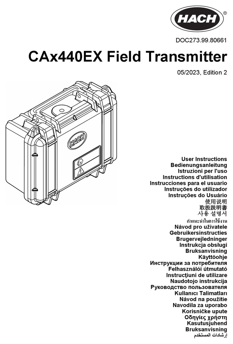
Hach CAx440EX User manual

DOC273.99.80684
CAx440EX Field Transmitter
04/2023, Edition 1
User Instructions
Bedienungsanleitung
Istruzioni per l'uso
Instructions d'utilisation
Instrucciones para el usuario
Instruções do utilizador
Instruções do Usuário
使用说明
取扱説明書
사용 설명서
Návod pro uživatele
Gebruikersinstructies
Brugervejledninger
Instrukcja obsługi
Bruksanvisning
Käyttöohje
Инструкции за потребителя
Felhasználói útmutató
Instrucţiuni de utilizare
Naudotojo instrukcija
Руководство пользователя
Kullanıcı
Návod na použitie
Navodila za uporabo
Korisničke upute
Οδηγίες χρήστη
Kasutusjuhend
Bruksanvisning

Table of Contents
English..............................................................................................................................4
Deutsch.......................................................................................................................... 20
Italiano............................................................................................................................ 36
Français......................................................................................................................... 52
Español.......................................................................................................................... 68
Português...................................................................................................................... 84
Português.................................................................................................................... 100
中文............................................................................................................................... 116
日本語........................................................................................................................... 131
한국어........................................................................................................................... 146
.................................................................................................................................. 161
Čeština......................................................................................................................... 177
Nederlands................................................................................................................. 193
Dansk............................................................................................................................209
Polski............................................................................................................................ 225
Svenska....................................................................................................................... 241
Suomi............................................................................................................................257
български................................................................................................................... 273
Magyar......................................................................................................................... 289
Română....................................................................................................................... 305
lietuvių kalba...............................................................................................................321
Русский........................................................................................................................336
Türkçe...........................................................................................................................352
Slovenský jazyk......................................................................................................... 368
2

Slovenski..................................................................................................................... 384
Hrvatski........................................................................................................................ 400
Ελληνικά...................................................................................................................... 416
eesti keel..................................................................................................................... 432
Norsk.............................................................................................................................447
.............................................................................................................................. 463
3

Table of Contents
1 Specifications on page 4
2 General information on page 5
3 Installation on page 11
4 Set the power to on on page 15
5 Close the cover on page 16
6 Add the site to Hach H2S Data on page 16
7 Safety guidelines for hazardous locations
on page 16
8 Hang or wall mount on page 17
9 Maintenance on page 19
10 Use Hach H2S Data on page 19
11 Accessories on page 19
Section 1 Specifications
Specifications are subject to change without notice.
Table 1 General specifications
Specification Details
Dimensions (W x H x D) 230 x 155 x 63 mm (9.0 x 6.1 x 2.5 in.)
Enclosure Polycarbonate, IP64/IP67
Weight 0.80 kg (1.76 lb)
Pollution degree 2 (product), 4 (installation environment)
Protection class III
Overvoltage category I
Environmental conditions Indoor and outdoor use
Power requirements One of the options that follow:
• Two field transmitter batteries supplied by the manufacturer, lithium, non-
rechargeable
• DC power supply (9–28 VDC, 1 A minimum)
Battery life 3 months (approximately)
Operating temperature -20 to 60 °C (-4 to 140 °F)
Storage temperature -20 to 60 °C (-4 to 140 °F)
Humidity 0 to 100% relative humidity
Altitude 2000 m (6562 ft) maximum
Interface Status LED and on/off switch
Antenna Internal (optional: external)
Connectivity 4G (LTE CAT-M1) cellular (embedded SIM card)
Mounting Hang, wall mount or DIN-rail
Certifications - Safety cETLus Listed (5022889)
Certifications - Radio FCC (US), FCC ID: 2ANPO00NRF9160, ISED (Canada), IC:24529-NRF9160
4 English

Table 1 General specifications (continued)
Specification Details
North America (US/Canada) Certificate: Intertek ETL23CA104847186X
Class I, Division 2, Groups A-D (Class I, Zone 2, Group IIC)
Equipment providing intrinsically safe outputs:
[Ex ia] Class I, Division 1, Groups A-D
[AEx ia Ga] IIC and [Ex ia Ga] IIC
-20 °C ≤ Tamb ≤ +60 °C
Conforms to UL: 121201, 60079-0, 60079-11, 913, 61010-1
Certified to CSA C22.2: #213, #60079-0, #60079-11, #61010-1
Warranty 1 year
Table 2 Cloud data specifications
Specification Details
Cloud data service Hach H2S Data
Data Hydrogen sulfide (H2S) in liquid (mg/L)
Hydrogen sulfide (H2S) in gas (ppm)
Temperature (°C)
Time resolution 1 minute
Transmission frequency to Hach
H2S Data1< 15 minutes after event: Continuous
15–60 minutes after event: 15 minutes
1–6 hours after event: 1 hour
> 6 hours after event: 6 hours (to decrease power and cellular data use)
Events:
• Power switch is set to on.
• Battery replaced
• New sensor connected
• Sensor calibration started
Note: The transmission frequency does not change if a DC power supply is connected to
the field transmitter.
Compatible devices Computer or mobile device
Compatible browsers Chrome, Edge, Safari, Firefox
Data export Excel (CSV file)
System integration option Standardized REST API
Section 2 General information
In no event will the manufacturer be liable for damages resulting from any improper use of product or
failure to comply with the instructions in the manual. The manufacturer reserves the right to make
changes in this manual and the products it describes at any time, without notice or obligation.
Revised editions are found on the manufacturer’s website.
1For continuous data transmission during long-term operation, connect the "4-20mA 24V"
terminal (4–20 mA analog output) of the field transmitter to a device (e.g., SCADA or PLC).
English 5

2.1 Safety information
The manufacturer is not responsible for any damages due to misapplication or misuse of this product
including, without limitation, direct, incidental and consequential damages, and disclaims such
damages to the full extent permitted under applicable law. The user is soley responsible to identify
critical application risks and install appropriate mechanisms to protect processes during a possible
equipment malfunction.
Please read this entire manual before unpacking, setting up or operating this equipment. Pay
attention to all danger and caution statements. Failure to do so could result in serious injury to the
operator or damage to the equipment.
Make sure that the protection provided by this equipment is not impaired. Do not use or install this
equipment in any manner other than that specified in this manual.
2.1.1 Use of hazard information
D A N G E R
Indicates a potentially or imminently hazardous situation which, if not avoided, will result in death or serious injury.
WARNING
Indicates a potentially or imminently hazardous situation which, if not avoided, could result in death or serious
injury.
CAUTION
Indicates a potentially hazardous situation that may result in minor or moderate injury.
N O T I C E
Indicates a situation which, if not avoided, may cause damage to the instrument. Information that requires special
emphasis.
2.1.2 Precautionary labels
Read all labels and tags attached to the instrument. Personal injury or damage to the instrument
could occur if not observed. A symbol on the instrument is referenced in the manual with a
precautionary statement.
This is the safety alert symbol. Obey all safety messages that follow this symbol to avoid potential
injury. If on the instrument, refer to the instruction manual for operation or safety information.
This symbol indicates that a risk of electrical shock and/or electrocution exists.
This symbol indicates that the marked item requires a protective earth connection. If the instrument is
not supplied with a ground plug on a cord, make the protective earth connection to the protective
conductor terminal.
This symbol indicates the presence of devices sensitive to Electro-static Discharge (ESD) and
indicates that care must be taken to prevent damage with the equipment.
Electrical equipment marked with this symbol may not be disposed of in European domestic or public
disposal systems. Return old or end-of-life equipment to the manufacturer for disposal at no charge to
the user.
6 English

2.2 Hazardous location (North American classification)
The CAx440EX field transmitter is made for use in explosion hazardous areas and is an Ex-barrier
module for the GS2440EX sensor.
The field transmitter is a power supply and a radio communication device. The field transmitter
supplies power to the GS2440EX sensor and transmits data from the GS2440EX sensor to the Hach
H2S Data cloud server.
The field transmitter can be installed as an “associated apparatus” in the safe area, where the field
transmitter operates as a normal barrier module. Also, the field transmitter is an accessory for use in
explosion hazardous areas (Division 2) and works as an Ex barrier that supplies intrinsically safe
outputs to Division 1 equipment (e.g., the GS2440EX sensor). The field transmitter must be operated
in the battery-power configuration when installed in a hazardous location.
Since the field transmitter can be installed in the "safe area" as an “associated apparatus” and as an
Ex barrier in Division 2, it is important for the safety of the user that the installation instructions from
the manufacturer are obeyed.
Conditions of use:
• Use only batteries with the part number LXZ449.99.00003 and delivered by the “Hach Company”
with the CAx440EX field transmitter. Use of other batteries with the CAx440EX field transmitter
may have an effect on the Ex-safety and voids the hazardous location certification.
WARNING
Explosion hazard. The batteries must only be changed in an area free of ignitible concentrations.
Do not connect or disconnect when energized.
Do not disconnect while the circuit is live or unless the area is free of ignitible concentrations.
Intrinsic safety—specific conditions of use:
Inductance and capacitance values specified for the connections Power/4-20 mA and RS-232 have
not been determined for simultaneous combination. Precautions must be used to make sure that the
combination of resistive, inductive and capacitive energies cannot cause an incendive spark. Refer to
IEC 60079-25 for de-rating instructions. Use with the GS2440EX sensor with cables up to
120 meters has been determined to be safe.
2.3 Radio (cellular)
CAUTION
This equipment is not intended for use in residential environments and may not provide adequate protection to
radio reception in such environments.
CAUTION
Electromagnetic radiation hazard. Make sure that the antenna is kept at a minimum distance of 20 cm
(7.9 in.) from all personnel in normal use. The antenna cannot be co-located or operated in
conjunction with any other antenna or transmitters.
N O T I C E
Network and access point security is the responsibility of the customer that uses the wireless instrument. The
manufacturer will not be liable for any damages, inclusive however not limited to indirect, special, consequential
or incidental damages, that have been caused by a gap in, or breach of network security.
The CAx440EX field transmitter includes a cellular modem. The field transmitter is approved for
mobile and fixed use with respect to RF exposure compliance. During cellular transmission, keep a
minimum distance of 20 cm (7.9 inches) between the field transmitter and the user to obey regulatory
requirements.
In addition, the compliance regulations that follow are met:
• FCC (US) - Title 47CFR, Part 15B, 22H, 24E, 27, 90
• ISED (Canada) - ICES-003, RSS 130, 132, 133, 139, 140
English 7

Note: Specifications are subject to change without notice.
The cellular options in Table 3 are available with the CAx440EX field transmitter.
Table 3 Cellular options
Cellular model Frequency bands Maximum power Data transmission
Nordic nRF9160
(LXV449.98.01010) Cat-M1 Bands: B1, B3, B8, B20, B66 23 dBm 4G (LTE Cat M1)
An optional external cellular antenna is available for use with the CAx440EX field transmitter
(maximum gain 6 dBi).
Note: To keep regulatory compliance, use only the external antenna for the CAx440EX field transmitter that is
approved by the manufacturer (LXZ449.99.00009).
2.4 Icons used in illustrations
User supplied parts Do one of these options
2.5 Product overview
The CAx440EX field transmitter is used with a GS1440 or GS2440EX sensor. The field transmitter
supplies power to the sensor through the Power/4–20 mA sensor cable and receives the sensor
measurements through the Power/4–20 mA and RS-232 sensor cables.
The field transmitter transmits the hydrogen sulfide and temperature measurements (RS-232 signal)
to a cloud service called Hach H2S Data. Refer to Use Hach H2S Data on page 19.
In addition, the field transmitter can supply the sensor measurements (4–20 mA analog output) to a
device (e.g., SCADA or PLC).
Figure 1 and Figure 2 give an overview of the field transmitter.
8 English

Figure 1 External view
1 Enclosure 4 Activation code
2 Latch 5 QR code for Hach H2S Data
3 Multi tool
Table 4 Status LED
Color Status
Green, one flash Connected to cellular network
Green, three flashes Connection to cellular network in progress
Green, steady Data transmission to a cellular network
Yellow, one flash The sensor is not connected.
Red, one flash Cannot connect to a cellular network
English 9

Figure 2 Internal view
1 Mounting screws (4x) 6 "4-20mA 24V" terminal for device
2 Status LED (Table 4)7 "DC 9–28V" terminal2
3 "RS-232 SENSOR CABLE" terminal 8 Power switch
4 "4–20mA SENSOR CABLE" terminal 9 Internal antenna cable
5 Battery terminals 10 Cable glands
2.6 Product components
Make sure that all components have been received. Refer to Figure 3. If any items are missing or
damaged, contact the manufacturer or a sales representative immediately.
Figure 3 Product components
1 CAx440EX field transmitter 2 Multi tool
2A DC power supply can be used as an alternative to the batteries or with the batteries.
10 English

Section 3 Installation
D A N G E R
Explosion hazard. Trained personnel only must install or commission the equipment.
3.1 Open the cover
The cover can be opened with the latch on the left side or the right side.
3.2 Connect the sensor cables
D A N G E R
Explosion hazard. Do not connect wires when an explosive atmosphere is present.
1. Connect the Power/4–20 mA sensor cable (3-wires) to the "4–20mA SENSOR CABLE" terminal.
Refer to Table 5 and Figure 4 on page 14.
2. Connect the RS-232 sensor cable (4-wires) to the "RS-232 SENSOR CABLE" terminal. Refer to
Table 6 and Figure 4 on page 14.
English 11

Table 5 "4–20mA SENSOR CABLE" terminal—Wiring information
Terminal color Wire color Signal
Brown Brown Positive
Blue Blue Negative
White Silver Shield
Table 6 "RS-232 SENSOR CABLE" terminal—Wiring information
Terminal color Wire color Signal
Brown Brown Sensor RXD (receive)
Blue Blue Sensor TXD (transmit)
Black Black GND (ground)
White Silver Shield
3.3 Connect power
D A N G E R
Explosion hazard. Do not install or replace the batteries or connect power when an explosive
atmosphere is present.
WARNING
Explosion and fire hazard. Battery substitution is not permitted. Use only batteries that are supplied by
the instrument manufacturer.
WARNING
Explosion hazard. Incorrect battery installation can cause the release of explosive gases. Make sure
that the batteries are inserted in the correct polarity orientation.
WARNING
Explosion hazard. Non-rechargeable batteries can leak or explode if charged. Do not put non-
rechargeable batteries into a battery charger.
Connect power with one or two of the options that follow:
•Batteries—Install two field transmitter batteries. Refer to Figure 5 on page 15. To keep the
electrical safety and hazardous location rating of the field transmitter, only use batteries supplied
by the manufacturer. Refer to Accessories on page 19 for ordering information. Install and
replace the batteries one at a time.
•DC power supply—Connect a DC power supply to the "DC 9–28V" terminal (9 to 28 VDC, 1 A
minimum). Refer to Table 7 and Figure 5 on page 15.
Table 7 "DC 9–28V" terminal—Wiring information
Terminal Signal Terminal Signal
1 (left) VDC + 2 (right) Ground
12 English

3.4 Connect the 4–20 mA analog output (optional)
Connect the 4-20 mA analog output of the field transmitter to a device (e.g., SCADA or PLC) as
necessary. Refer to Table 8 and Figure 5 on page 15.
The 4–20 mA analog output represents the sensor measurement. For the measurement range
represented by the 4-20 mA analog output, refer to "Change the measurement units" in the sensor
documentation.
Table 8 "4–20mA 24V" terminal—Wiring information
Terminal Signal Terminal Signal
1 (left) Loop + 2 (right) Loop -
3.5 Electrical wiring overview
Figure 4 shows how to connect the two sensor cables to the field transmitter.
Figure 5 shows how to connect a DC power supply3 and install the batteries in the field transmitter. In
addition, Figure 5 shows how to connect the 4-20 mA analog output of the field transmitter to a
device.
To keep the environmental rating of the enclosure, make sure that there is a plug in the cable gland
that is not used, if applicable.
3A DC power supply can be used as an alternative to batteries or with the batteries.
English 13

Figure 4 Electrical wiring overview—Sensor cables
14 English

Figure 5 Electrical wiring overview—DC power and 4–20 mA analog output
Section 4 Set the power to on
1. Make sure that the sensor cables are connect to the sensor.
2. Set the power switch to "ON".
The field transmitter automatically connects to a cellular network.
3. Wait 2 to 3 minutes.
4. Make sure that the status LED on the field transmitter is green.
Note: To conserve battery life, the data transmission frequency of the field transmitter changes after the field
transmitter is set to on. Refer to Table 2 on page 5.
English 15

Section 5 Close the cover
Section 6 Add the site to Hach H2S Data
1. Scan the QR Code on the field transmitter with a mobile device or enter the activation code at
https://h2sdata.hach.com.
Hach H2S Data opens on the mobile device.
2. Log in or register with a username and password, if prompted.
3. Enter the name and location of the installation site. Refer to the instructions that show on the
computer screen.
Section 7 Safety guidelines for hazardous locations
D A N G E R
Obey all North American Classification Certificate specifications as well as national and local
regulations.
Obey the safety warnings of the other intrinsically safe (Ex) equipment installed near the field
transmitter and sensor.
Do not wipe or clean the field transmitter while in a hazardous location. Only clean the field
transmitter with a wet cloth.
Use only batteries supplied by the manufacturer in the field transmitter.
Installation of the instrument into hazardous locations must be done so that no friction can be
generated between the instrument and any surrounding surfaces.
The instrument is for fixed installation. Keep direct airflow away from the instrument, which can cause
an electrical charge transfer.
16 English

Section 8 Hang or wall mount
D A N G E R
Explosion hazard. Installation of the instrument into hazardous locations must be done so that no
friction can be generated between the instrument and any surrounding surfaces.
The instrument is for fixed installation. Keep direct airflow away from the instrument, which can cause
an electrical charge transfer.
To hang the field transmitter, attach the crossbeam clamps to the field transmitter. Refer to the
illustrated steps in Figure 6. Refer to Accessories on page 19 for ordering information.
To attach the field transmitter to a wall or DIN rail, attach the wall mount bracket to the field
transmitter. Refer to Accessories on page 19 for ordering information. Installation instructions are
supplied with the wall mount bracket.
English 17

Figure 6 Attach the crossbeam clamps
18 English

Section 9 Maintenance
N O T I C E
Do not disassemble, modify or repair the instrument. Disassembly will damage the sensor and void the warranty.
If the internal components must be repaired, contact the manufacturer.
Section 10 Use Hach H2S Data
Use Hach H2S Data to look at the sensor measurements and to export the sensor measurements as
a CSV (comma-separated value) file. Refer to for the transmission frequency of the field transmitter.
Hach H2S Data shows:
• An overview of all of the sites
• Interactive graphs
• Data comparisons of multiple sites
• Device status (e.g., battery level)
To go to Hach H2S Data, scan the QR Code on the field transmitter with a mobile device or go to
https://h2sdata.hach.com.
Go to Hach Support Online to watch the training video for Hach H2S Data.
(Optional) An API programmer can use the Standardized REST API (application programming
interface) to send the sensor measurements from Hach H2S Data to other systems. The API Guide is
available on Hach H2S Data.
Section 11 Accessories
WARNING
Personal injury hazard. Use of non-approved parts may cause personal injury, damage to the
instrument or equipment malfunction. The replacement parts in this section are approved by the
manufacturer.
Note: Product and Article numbers may vary for some selling regions. Contact the appropriate distributor or refer to
the company website for contact information.
Description Item no.
Antenna, external for CAx440EX field transmitter, EU, UK, USA and Canada, 2 m
(6.5 ft) cable, IP68
Ø100 x 36 mm (Ø3.9 x 1.4 in.), LTE: 6 dBi, Frequency band: 698-3800 MHz LXZ449.99.00009
Batteries (8x), CAx440EX field transmitter, lithium, non-rechargeable LXZ449.99.00003
Crossbeam clamps, CAx440EX field transmitter, EU, UK, USA and Canada LXZ449.99.00008
Mounting bracket for CAx440EX field transmitter, USA and Canada LXZ449.99.00018
Crossbeam for 558-858 mm (22.0-33.8 in.) manhole with crossbeam clamps
Stainless steel EN 1.4404, 3.4 kg (7.5 lb), 558-858 x 136 x 71 mm ( 22.0-33.8 x 5.4 x
2.8 in.) LXZ449.99.00007
English 19

Inhaltsverzeichnis
1 Spezifikationen auf Seite 20
2 Allgemeine Informationen auf Seite 21
3 Installation auf Seite 27
4 Einschalten auf Seite 31
5 Schließen der Abdeckung auf Seite 32
6 Standort zu Hach H2S Data hinzufügen auf Seite 32
7 Sicherheitsrichtlinien für gefährliche Standorte
auf Seite 32
8 Aufhängung oder Wandmontage auf Seite 33
9 Instandhaltung auf Seite 35
10 Nutzung von Hach H2S Data auf Seite 35
11 Zubehör auf Seite 35
Kapitel 1 Spezifikationen
Änderungen vorbehalten.
Tabelle 1 Allgemeine technische Daten
Spezifikationen Details
Abmessungen (B x H x T) 230 x 155 x 63 mm
Gehäuse Polycarbonat, IP64/IP67
Gewicht 0,80 kg
Verschmutzungsgrad 2 (Produkt), 4 (Installationsumgebung)
Schutzklasse III
Überspannungskategorie I
Umgebungsbedingungen Verwendung im Innen- und Außenbereich
Stromanforderungen Eine der folgenden Optionen:
• Zwei vom Hersteller bereitgestellte Feldtransmitter-Batterien, Lithium, nicht
wiederaufladbar
• DC-Netzteil (9 - 28 VDC, mindestens 1 A)
Batterielebensdauer 3 Monate (ungefähr)
Betriebstemperatur -20 bis 60 °C (-4 bis 140 °F)
Lagerungstemperatur -20 bis 60 °C
Luftfeuchtigkeit 0 bis 100 % relative Luftfeuchtigkeit
Höhe Maximal 2000 m
Schnittstelle Status-LED und Ein-/Aus-Schalter
Antenne Intern (optional: extern)
Verbindung 4G (LTE CAT-M1) Mobilfunk (integrierte SIM-Karte)
Montage Aufhängung, Wandmontage oder DIN-Schiene
Zertifizierungen – Sicherheit cETLus-zertifiziert (5022889)
Zertifizierungen – Funk FCC (USA), FCC-ID: 2ANPO00NRF9160, ISED (Kanada), IC:24529-NRF9160
20 Deutsch
Other manuals for CAx440EX
1
Table of contents
Other Hach Transmitter manuals
Popular Transmitter manuals by other brands

DMP Electronics
DMP Electronics 1103 Series installation guide

Intra Automation
Intra Automation ITA-T1S technical information

enika
enika P8 T 2AN DIN quick start guide

Optical Systems Design
Optical Systems Design OSD9003 Operator's manual

Nulaxy
Nulaxy KM18 user manual

Broadcast Electronics
Broadcast Electronics FM-10T manual