HAGER WERKEN BRAVO PORTABLE II PLUS User manual

Handbuch / Manual / Manuel
BRAVO PORTABLE II PLUS

BRAVO PORTABLE II PLUS
D Tragbare Steuerbox und Mikromotor - Handbuch
1. Produktmerkmale
• Max. 30.000 RPM
• Akkulaufzeit: max. 8 Stunden
Angewendetes Handstück (12V) Höchstgeschwindigkeit Akkulaufzeit
SH300, SH300S, H200 M300Es 30.000 RPM 8 Stunden
MH20, MH20E 20.000 / 30.000 RPM
• Ladezeit des Akkus: 3 Stunden • Sicherheitsschutzsystem
• RPM Digitalanzeige • Vorwärts- / Rückwärtswechselfunktion
• LED-Anzeige für Akkuladung • Ein / Aus Fußstütze
(Stufe 3) • Standardbit 2,35 mm angewendet
• Drehzahlsteuerung: Handwahl • Pause-Funktion
Lesen Sie vor dem Gebrauch unbedingt die Bedienungsanleitung durch.
2. Name der Produktkomponenten
Rückansicht Seitenansicht
Vorderansicht
Handstück
E-Typ Handstück
madein korea
Steuerbox a) Ein- / Ausschalter d) Geschwindigkeitsregler
b) Rücktaste e) Ladeadapteranschlussbuchse
c) Fußstützetaste / Pause-Taste f) Fußstützeanschlussbuchse
Handstück / E-Typ Handstück
Handstück Wiege Steuerbox Halter (optional)
Ein- / Aus-Fußstütze Ladeadapter
Clip (optional) Handstückhalter (optional)
Digitales RPM-Anzeigefenster
EIN / Geschwindigkeitsanzeigefenster Fußstütze-Anzeigefenster,
(00-30) Pause-funktion
Überlastwarnungsfenster Akkuladung- / Pegelanzeige
Akkuladeanzeigefenster Handstück-Anschlussbuchse
Rückwärts-Anzeigefenster
(Optional: Tasche, Bohrer-Beutel, Nagelschieber, Nagelbit)
3. Bedienung
(1) Akkuladung (Ladezeit: 3 Stunden)
• Den DC-Stecker des Ladeadapters mit Anschlussbuchse der Steuerbox
verbinden und aufladen.
• Während des Ladevorgangs blinkt die LED , wenn die LED grün blinkt, ist
der Akku vollständig aufgeladen
• LED-Anzeige nach Akkuladung / Pegel
Schritt 1 (Minimum) Schritt 2 (Mitte) Schritt 3 (volle Ladung)
• Nachdem der Ladevorgang abgeschlossen ist, kann es nach dem Trennen des
Adapters betrieben werden. Der Handstückbetrieb ist während des Ladens
möglich. Aber wenden Sie es nicht an.
• Um eine Überhitzung des Akkus zu vermeiden, müssen Sie den
Adapter nach Abschluss des Ladevorgangs abziehen.
• Verwenden Sie zum Laden des Steuergeräts nur Original-Ladeadapter
und -Netzkabel.
(2) Handstückbetrieb
• Die Steuerbox mit dem Handstück verbinden.
• Während das Handstück angeschlossen ist, den Ein- / Ausschalter mindestens
1 Sekunde lang gedrückt halten.
• Im Falle einer Wählscheibe, die Wählscheibe von MIN > MAX zum Betrieb drehen.
• Wenn Sie die Rückwärts-Taste drücken, leuchtet die LED grün und
arbeitet in umgekehrter Richtung.
(3) Fußstützebetriebsmodus / pause
• Die Fußstütze mit der Fußanschlussbuchse am Steuerkasten verbinden.
• Die LED-Anzeige leuchtet grün, wenn Sie die Fußtaste anwenden.
• Der Fußstütze betriebsmodus ist bei eingestellter Geschwindigkeit ein / aus.
4. Bits anwenden
• Wenn Sie das Spannfutter öffnen, drehen Sie den Griff gegen den Uhrzeigersinn
und entfernen Sie den Meißel.
• Wenn Sie das Spannfutter schließen, drehen Sie den Griff im Uhrzeigersinn,
um das Spannfutter zu schließen, und das Bit einzusetzen.
• Wenden Sie das Standardbit an und halten Sie dies sauber.
5. Sicherheitsschutzsystem
(1) Automatische Ausschaltfunktion: Wenn keine Aktion bei eingeschaltetem
Gerät erfolgt, schaltet es sich automatisch nach 3 Minuten aus.
(2) Automatische Ausschalt- und Rücksetzvorrichtung bei Überlastung:
Die LED leuchtet orange, wenn sie überlastet ist, und die Steuerbox wird nach 5
Sekunden automatisch ausgeschaltet und zurückgesetzt.
Reaktivierung: Drehen Sie den Geschwindigkeitsregler auf MIN, um es reaktivieren.
6. Vorsichtshinweise
• Wenden Sie das Produkt nur an einem geplanten Arbeitsplatz, nicht an einem
feuchten Ort, an. (Temperatur: -20°C bis 40°C, Luftfeuchtigkeit: 0 bis 90% rF).
• Achten Sie darauf, dass das Handstück nicht fällt. Dies kann zu Funktions-
störungen führen und die Lebensdauer der Lagern und des Motors wird reduziert.
• Achten Sie darauf, dass keine Flüssigkeiten wie Wasser oder Öl in das Handstück gelangen.
• Achten Sie bei geöffnetem Spannfutter des Handstücks darauf, dass der Strom erst nicht
eingeschaltet wird und das Handstück nicht betrieben wird.
• Schließen Sie das Netzkabel an die Steckdose an, nachdem Sie sichergestellt haben, dass es
ausgeschaltet ist.
• Wenden Sie es nicht für andere Zwecke als zum gezielten Arbeiten an.
Batterie Warnung
• Die angewendete Batterie ist Lithium-Ionen-Batterie und
Verbrauchsmaterial.
• Wenn die Betriebszeit kurz ist oder nicht mit voller
Geschwindigkeit arbeitet, ersetzen Sie die Batterie.
• Wenden Sie sich an Ihren Händler, um die Batterie auszutauschen
und zu kaufen.
• Die Entsorgung oder das Recycling unterliegt den nationalen Vorschriften.
7. Produkt Garantie
• Zeitraum: 1 Jahr
• Wir haften nicht für Unaufmerksamkeit oder Fahrlässigkeit des Benutzers und
Verbrauchsmaterial.
8. Fehlerbehebung
Probleme Ursache Maßnahme
• Motor funktioniert
nicht, auch wenn die
Steuerbox voll aufgela-
den ist.
• Lose Verbindung zwischen
Steuerboxbuchse und Motor-
kabel
• Motorkabel an Steuerboxbuchse
richtig verbinden
• Defektes Motorkabel • Motorkabel ersetzen
• Das Leben der Kohlebürste
ist erschöpft.
• Kohlebürste ersetzen
• Defekter Motor • Wenn ein Problem mit dem Mo-
tor selbst vorliegt, den Motor repa-
rieren
• Motorbetrieb wurde
plötzlich angehalten.
• Bei Betrieb mit Überlast
oder mit geöffnetem Spann-
futter
• Sicherheitsschutzsystem Nr. 4
prüfen.
• Wenn das Spannfutter geöffnet
ist, es schließen.
• Falls der Motor bei
Fußstützebetriebsmo-
dus nicht funktioniert,
• Falls die H / F-Taste „H” ist,
• Falls die Fußstütze nicht
funktioniert,
• Die Taste mit “F” einstellen
• Die Fußstützeüberprüfen und
austauschen
Wenn das Problem nach der Maßnahme nicht behoben wird, wenden Sie sich bitte an die
Verkaufsstelle.
9. Produktspezifikation Tabelle
Steuerbox Eingabe
(Vdc)
Ausgabe
(Vdc)
Strom
(W)
Gewicht
(g) Größe
Bravo Portable II Plus 12 12 24 285 67 128 30
Handstück Eingabe
(V)
Dreh-
moment
(Ncm)
Dreh-
zahl
(rpm)
Gewicht
(g)
Größe
Ø L
SH300 DC12 2,4 30.000 143 22 129
SH300S DC12 2,4 30.000 135 23 135
H200 DC12 2,7 30.000 138 25 119
MH20 DC12 2,2 20.000/
30.000 125 21 131
M300Es DC12 2,4 30.000 130 22,5 97
MH20E DC12 2,2 20.000 70 20 96
Ladeadapter Eingabe Ausgabe
100~240V, 50/60Hz 12Vdc / 2.0A
HAGER & WERKEN GmbH & Co.KG Ackerstraße 1 47269 Duisburg, Germany T +49(203) 99 269-0 F +49 (203) 299283 www.hagerwerken.de

BRAVO PORTABLE II PLUS
GB Portable control box & Micro-motor - Manual
Please be sure to read this manual before operation.
1. Precaution
• Install the unit at your workplace and do not use in a dirty or very hot and humid
environment.(-20°C, -40°C, 0-90% RH).
• Please take care not to drop the hand piece or drill unit. This will result in damage to ball
bearing and will affect the durability of the motor.
• Please do not allow water or other liquids to spill onto and into all units.
• After replacing a bur, please make sure to close the chuck handle.
• Do not open the chuck handle while the hand piece is in operation.
• While the hand piece is not in operation, it is recommended to leave a drill bit (bur)
inserted into the chuck after cleaning.
• Bravo Portable II Plus is a professional use only device, for use by professionals only.
Warning about battery usage
• The battery is a LI-ION rechargeable battery (consumable goods)
• Battery lifetime is limited and depends on working conditions.
• When it doesn’t reach maximum speed, it will be time to replace batteries.
• Please dispose used batteries in accordance with the national and local laws.
2. Features
• Max speed : 30,000 RPM
• Run-time : Max 8 hrs.
Max. speed
SH300, SH300S, H200 M300Es 30,000 RPM 8 hrs.
MH20, MH20E 20,000 / 30,000 RPM
• Charging time : 3 hrs. • Automatic power saving function
• RPM digital display • Forward / Reverse rotation
• Rechargeable battery level display • On / off foot switch
(3 steps) • Use with the standard bit (bur)
• Two ways of speed control : Speed control dial & button
3. Part introduction
Back view Side view
Front view
Handpiece
E-Type Handpiece
madein korea
Clip Type (Optional)
Control box a) Power button d) Speed control dial & button
b) Forward/Reverse button e) Adaptor connector
c) Hand/Foot button f) Foot switch connector
Handpiece / E-type handpiece
Handpiece stand
Control box stand (optional)
On/Off foot switch (optional)
Adaptor
Power cord
Clip (optional)
Handpiece holder (optional)
RPM Digital display
ON/speed display(00-30) Foot mode display,
Overload warning display Pause function
Charging display
Battery level display
Reverse mode display Handpiece connector
4. Installation & Operation
4-1. Battery recharging (Charging time : 3hrs.)
1) Connect the DC plug to the adaptor connector of control box.
2) While battery is charging, LED blinks. When it is fully charged, LED light remains on.
3) Rechargeable battery level display (3 steps)
1 step (low) 2 step (medium) 3 step (high)
• To prevent from overheating, please be sure to separate the adaptor from the
control box. Also,please avoid operating the unit during charging hours.
• When recharging, please make sure to use the original recharge adapter and
power cord.
4-2. Handpiece connection (in case of E-type micro-motor)
E-Type Micromotor
Straight
Handpi
ece
Conotra Angle
1) Insert a straight or a contra angle handpiece into the micro-motor
2) In case of the first use after purchasing a straight handpiece or a contra angle, please run
the handpiece under no load state, then use.
4-3. Operation by Hand
1) Connect the handpiece to a control box.
2) To turn on, press and hold the power button for 1 second
3) Please turn the speed control knob toward clockwise from MIN to MAX.
4) On the digital display a green light will appear - change the direction by pushing the
reverse button.
4-4. Operation by Foot
1) Connect a foot switch to a control box.
2) Turn a foot mode button , will be turned on a green light on a digital display.
3) In the foot mode, a handpiece will be operated within the limit of set speed.
4-5. Pause Funtion
1) Holding the foot mode button over a second will pause the operation of handpiece
5. Bur(Bit) insertion and removal
1) To remove a bur, please turn a chuck handle c¬¬lockwise until it clicks to stop, and then
pull out the bur.
2) To insert the bur, please turn the chuck handle counterclockwise until it clicks to stop.
3) Please be sure not to use bent, asymmetrical or damaged burs. Always use stand- ard burs.
6. Safety protection system
(1) Automatic power saving function: If there is no operation, the control box wil be power off
automatically after 3 minutes.
(2) Overload protection function:
If a control box gets overloaded, and overload warning display turns on in orange
light. The control box will stop after 5 seconds.
How to restart: Please set the dial to MIN to restart the unit after the overload stop.
7. Trouble shooting
Trouble Cause Remedy
Although a control
box is fully charged, a
handpiece fails to run.
Loose connection of a motor
cord with the motor
connector of control box.
Correctly plug the motor cord to
the motor connector of control
box.
Defect in the motor cord. Replace the motor cord.
Worn carbon brushes. Replace the carbon brushes.
Trouble in the motor part. Check the motor and repair if the
motor has a problem
Motor stops suddenly
while in use.
Overloaded or a chuck is
open in operation.
See No.6 Safety protection system.
Check the chuck and close the
chuck.
Motor fails to run
during a foot mode.
Foot switch fails to function Set it on “F”.
Check and replace the foot switch.
In case any malfunction is found, consult with an official dealer.
8. Maintenance
8-1. Replacing carbon brushes
1) After turning off the power, remove the carbon housing cover and motor cord from the
motor.
2) Take off carbon brush bolts, wi a screwdriver(+) and then remove worn-out carbon
brushes.
3) Replace with new carbon brushes carefully.
4) Assemble the handpiece.
5) After running the hand piece under no load state around 20,000 rpm for 30 minutes, you
may then use.
Replacement cycle of carbon brushes will depend on working hours and loadi-ng conditions.
Carbon Housing Cover Motor Cord
Brush Spring Carbon Brush
Bolt
Carbon Brush
Carbon Brush
Holder
8-2. Replacing collet chuck
1) A hand cap and a spindle assembly will be disassembled by turning the hand cap
countclockwise with a chuck wrench.
2) The collet chuck is disassembled by turning it countclockwise with a chuck joint wrench
and the chuck wrench.
3) Replace the old collet chuck with a new one and then assemble the handpiece.
4) Run the handpiece under no load state and confirm proper replacement, then use.
Replacement cycle of collet chuck will depend on working hours and loading conditions.

Chuck Wrench
Hand Cap
Spindle Set Chuck Wrench
Test Bur
Chuck Joint Wrench
8-3. Replacing ball bearings
1) Disassemble the hand cap and a spindle assembly from the front part of the handpiece.
2) If a C-ring is picked out of the front chuck housing, ball bearings and other supporting
parts will be disassembled.
3) Assemble other supporting parts and replace to new ball bearings sequentially, install
the C-ring again.
4) Assemble the hand cap and the spindle assembly.
5) Run the handpiece under no load state and confirm proper replacement, and then use.
Chuck Wrench
Hand Cap
C Ring
Spindle Set
Ball Bearing
Chuck Housing
9. Specification
Control Box Input
(Vdc)
Output
(Vdc)
Power
(W)
Weight
(g)
Dimension
W D H
Bravo Portable II Plus 12 12 24 285 67 128 30
Handpiece Input
(V)
Torque
(Ncm)
Max.
Speed
(rpm)
Weight
(g)
Dimension
Ø L
SH300 DC12 2.4 30.000 143 22 129
SH300S DC12 2.4 30.000 135 23 135
H200 DC12 2.7 30.000 138 25 119
MH20 DC12 2.2 20.000/
30.000 125 21 131
M300Es DC12 2.4 30.000 130 22,5 97
MH20E DC12 2.2 20.000 70 20 96
Adaptor Input Output
100~240V, 50/60Hz 12Vdc / 2.0A
10. Allowable rotation speed
This chart is a general guide for a maximum speed with conventional burs.
The allowable rotation speed can be slightly different, depending on bur materials or types.
Notice
1) Make sure not to extend the maximum speed specified by a manufacturer or distributor.
2) Large burs, even being operated below maximum speed, will vibrate.
Speed should be reduced immediately to prevent damage to a bur, a handpiece or
operator.
3) Be sure to insert the bur shank all the way, until it touches the back of the collet chuck,
then tighten a collect chuck. If the bur is used not inserted completely, it is very
dangerous.
Rotation speed (rpm)
50,000
45,000
40,000
35,000
30,000
25,000
20,000
15,000
10,000
5,000
0
more than Ø40 Ø 28-40 Ø 18-28 Ø 8-18 Ø 4-8Ø2-4 less than Ø 2
11. Warrant y
• We do not guarantee its quality in case of users’ carelessness.
HAGER & WERKEN GmbH & Co.KG Ackerstraße 1 47269 Duisburg, Germany T +49(203) 99 269-0 F +49 (203) 299283 www.hagerwerken.de

BRAVO PORTABLE II PLUS
F Boîtier de contrôle portable & Micromoteur
Veuillez lire attentivement ce manuel avant d'utiliser l'appareil.
1. Précautions
• Installez l'appareil sur votre lieu de travail et ne l'utilisez pas dans un environnement sale
ou très chaud et humide. (-20, -40, 0 à 90% HR)
• Veillez à ne pas laisser tomber la pièce à main ou l'unité de fraisage. Cela endommagera le
roulement à billes et affectera la durabilité du moteur.
• Ne laissez pas d'eau ou d'autres liquides s'écouler sur ou dans aucunes des unités.
• Après le remplacement d'une fraise, veillez à bien fermer la poignée du mandrin.
• N’ouvrez pas la poignée du mandrin lorsque la pièce à main est en service.
• Lorsque la pièce à main n'est pas en service, il est recommandé de laisser un foret (fraise)
inséré dans le mandrin après avoir nettoyé.
• Bravo Portable II Plus est un appareil réservé à un usage professionnel, destiné aux
professionnels uniquement.
Précautions concernant l'utilisation de la batterie
•La batterie est une batterie rechargeable LI-ION (biens de consommation)
• La durée de vie de la batterie est limitée et dépend des conditions d’utilisation.
• Lorsque la vitesse maximale n’est plus atteinte, cela signifie qu’il faut
remplacer la batterie.
• Veuillez jeter les batteries usagées conformément à la législation nationale
et locale en vigueur.
2. Caractéristique
• Vitesse max : 30,000 tr/min
• Durée de Fonctionnement : Max 8 hrs.
Pièce à main Vitesse Max Durée de fonctionnement
SH300, SH300S, H200 M300Es 30,000 tr/min 8 hrs.
MH20, MH20E 20,000 / 30,000 tr/min
• Temp de charge : 3h. • de contrôle de la vitesse Fonction automatique
• Affichage digital tr/min d'économie d'énergie
• Affichage du niveau de la batterie • Rotation avant / arrière
rechargeable (3 niveaux) • Pédale de commande Marche / Arrêt
• Deux modes de contrôle de la vitesse : • Utilise des forets standards (fraises)
Molette & bouton
3. Présentation des composants
Vue arrière Vue latérale
Vue avant
Pièce à main
Pièce à main de Type E
madein korea
Type de Clip (Optionnel)
Boîtier de contrôle a) Bouton d'alimentation d) Molette & bouton de contrôle
de vitesse
b) Bouton Avant/Arrière e) Connecteur adaptateur
c) Bouton Main/Pied f) Connecteur Pédale de Commande
Pièce à main / Pièce à main de type E
Support de la pièce à main
Support du boîtier de contrôle (optionnel)
Pédale de Commande Marche/Arrêt (optionnel)
Adaptateur
Cordon d'alimentation
Clip (optionnel)
Porte-pièce à main (optionnel)
Affichage digital tr/min
Affichage Marche/vitesse (00-30) Affichage mode Pied,
Affichage avertissement de surcharge Fonction Pause
Affichage de chargement
Affichage du niveau de la batterie
Affichage mode inversé Connecteur pièce à main
4. Installation & Utilisation
4-1. Recharge de la batterie (Temps de charge : 3h)
1) Connectez la fiche CC au connecteur de l'adaptateur du boîtier de contrôle.
2) Lorsque la batterie se charge, clignote. Lorsqu'elle est complètement chargée, le voyant
LED reste allumé.
3) Affichage du niveau de la batterie rechargeable (3 étapes)
1 niveau (bas) 2 niveau (moyen) 3 niveau (haut)
• Pour éviter toute surchauffe, veillez à séparer l'adaptateur du boîtier de
contrôle. De plus, veuillez éviter d'utiliser l'appareil pendant les heures de
charge.
• Lors de la recharge, assurez-vous d'utiliser l'adaptateur de recharge et le
cordon d'alimentation d'origine.
4-2. Assemblage de la pièce à main (dans le cas d’un micromoteur de type E)
Micromoteur de Ty pe E
Piè
ce à
main droite
Contre Angle
1) Insérer une pièce à main droite ou un contre-angle dans le micromoteur.
2) En cas de première utilisation après l'achat d'une pièce à main droite ou d'un contre-angle,
veuillez faire fonctionner la pièce à main à vide, puis utilisez.
4-3. Utilisation à la main
1) Connectez la pièce à main au boîtier de contrôle.
2) Pour allumer, appuyez sur puis maintenez enfoncé le bouton d'alimentation pendant
1 seconde.
3) Veuillez tourner le bouton de contrôle de vitesse dans le sens des aiguilles d'une montre de
MIN à MAX.
4) Sur l'affichage digital, un voyant vert s'allumera - changez la direction en appuyant
sur le bouton marche arrière.
4-4. Utilisation au Pied
1) Connectez la pédale de commande au boîtier de contrôle.
2) Tournez le bouton de mode pied , era allumé avec une lumière verte sur
l’affichage digital.
3) En mode pied, la pièce à main fonctionnera dans la limite de vitesse fixée.
4-5. Fonction Pause
1) Maintenir enfoncé le bouton du mode pied pendant plus d'une seconde interrompra
le fonctionnement de la pièce à main.
5. Insertion et enlèvement des fraises (forets)
1) Pour enlever une fraise, tournez la poignée du mandrin dans le sens des aiguilles d'une
montre jusqu'à ce qu'il se bloque, puis retirez la fraise.
2) Pour insérer une fraise, tournez la poignée du mandrin dans le sens inverse des aiguilles
d'une montre jusqu'à ce qu'il se bloque.
3) Veillez à ne pas utiliser de fraises tordues, asymétriques ou endommagées. Utilisez
toujours des fraises standards.
6. Système de sécurités
(1) Fonction automatique d'économie d'énergie : S'il n'y a aucune utilisation, le boîtier de
contrôle s'éteindra automatiquement après 3 minutes.
(2) Fonction de protection contre les surcharges :
Si le boîtier de contrôle surcharge et que le voyant d'avertissement de surcharge
s'allume en orange. Le boîtier de contrôle s'arrêtera après 5 secondes.
Comment redémarrer : Veuillez régler la molette sur MIN pour redémarrer l'appareil
après l’arrêt dû à une surcharge.
7. Dépa nna ge
Problème Cause Solution
Malgré que le boîtier
de contrôle soit com-
plètement chargé, la
pièce à main ne foncti-
onne pas.
Mauvaise raccordement du
cordon moteur avec le con-
necteur moteur du boîtier de
contrôle.
Raccordez correctement le cordon
moteur sur le connecteur moteur
du boîtier de contrôle.
Cordon moteur défectueux Remplacez le cordon moteur.
Balais carbone usagés. Remplacez les balais carbone.
Problème dans la partie
moteur.
Vérifiez le moteur et réparez si le
moteur a un problème.
Le moteur s'arrête
brusquement pendant
l'utilisation.
Surcharge ou mandrin ou-
vert lors de l’utilisation.
Voir 6. Système de sécurité. Vér-
ifiez et fermez le mandrin.
Le moteur ne
fonctionne pas en
mode pied.
La pédale de commande ne
fonctionne pas.
Set it on Réglez sur "F".
Vérifiez et remplacez la pédale de
commande.
cas de dysfonctionnement, contactez un revendeur officiel.
8. Entretien
8-1. Remplacement des balais carbone
1) Après avoir mis hors tension, enlevez le couvercle du boîtier carbone et le cordon du
moteur.
2) Retirez les vis des balais carbone, avec un tournevis (+) et enlevez les balais carbone usagés.
3) Remplacez soigneusement avec des balais carbone neufs.
4) Réassemblez la pièce à main.
5) Après avoir fait tourner la pièce à main à vide à environ 20 000 tr/min pendant 30 minutes,
vous pouvez ensuite l'utiliser.
Le cycle de remplacement des balais carbone dépend des heures d’utilisation et des conditions
de chargement.
This manual suits for next models
1
Table of contents
Languages:
Other HAGER WERKEN Dental Equipment manuals

HAGER WERKEN
HAGER WERKEN Bravo Portable II User manual

HAGER WERKEN
HAGER WERKEN PRAXIPOL PS II User manual

HAGER WERKEN
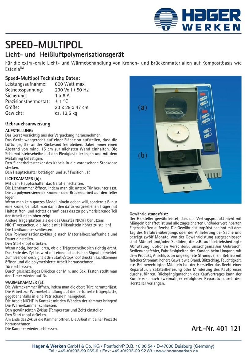
HAGER WERKEN SPEED-MULTIPOL User manual

HAGER WERKEN
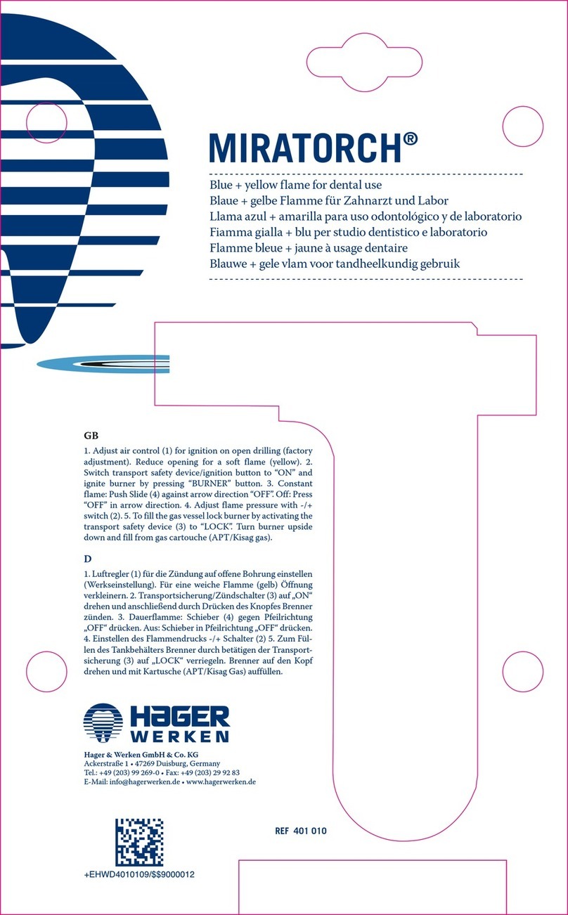
HAGER WERKEN MIRATORCH User manual

HAGER WERKEN
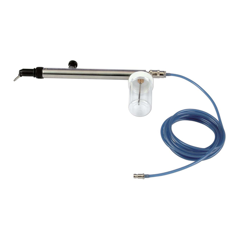
HAGER WERKEN Airsonic Mini-Sandblaster User manual

HAGER WERKEN
HAGER WERKEN LaserHF standard User manual