hager BA7CUTTER User manual

Sicherheitshinweise, Bestimmungsgemäße
Verwendung, Inbetriebnahme, Bedienung,
Wartung, Ersatzteilliste.
Vor Inbetriebnahme lesen und
aufbewahren ! DE 01
Safety instructions, Specified, Conditions of Use,
Commissioning, Operation, Maintenance, Spare
Parts List.
Please read and save these
instructions ! GB 09
Norme di sicurezza, uso previsto, messa in
funzione, funzionamento, manutenzione e distinta
dei pezzi di ricambio.
Prima della messa in funzione
leggere e conservare queste
istruzioni ! I17
Cesoia da banco per canali da cablaggio
I
GB Bench mount wiring duct cutting tool
RoHS
COMPLIANT
2
Hager Vertriebsgesellschaft mbH & Co. KG
Zum Gunterstal
66440 Blieskastel
Telefon 06842 945-0
www.hager.de
DE Verdrahtungskanalschneider
BA7CUTTER

2601
Achtung
Sicherheitshinweise
Die Messerschneide ist sehr scharf. Nicht in den Schneidbereich und an die
Messerschneide fassen.
Der Schneidbereich ist stets sauber zu halten. Mit geeigneten, sicheren Hilfsmitteln
(Verletzungsgefahr) vorhandene Teile, z.B. Späne, Abfallstücke, entfernen.
Das Gerät darf nur auf stabiler, kippsicherer Unterlage komplett fest montiert in Betrieb
genommen werden. Das Material zur Befestigung des Gerätes ist nicht enthalten. Bitte
verwenden sie entsprechend dem Untergrund geeignetes, stabiles Befestigungsmaterial.
Für optimales Schnittergebnis und Funktion des Gerätes, muß das Messer stets scharf
sein. Wenn stumpf ist das Messer zu erneuern.
Der federnde Messerschutz muß nach dem Schneidvorgang umgehend wieder an das
Messer hochklappen. Sollte diese Funktion defekt sein, ist das Messer sofort gegen
Verletzung zu sichern oder zu entfernen. Der Messerschutz muß vor erneuter Inbe-
triebnahme repariert oder ausgetauscht werden.
Bestimmungsgemäße Verwendung
Mit dem BA7CUTTER können Verdrahtungskanäle und entsprechende Deckel aus Kunst-
stoff bis zu einer Breite von 125 mm und einer Wandstärke bis 2,5 mm geschnitten
werden. Geeignet für weiche Kunststoffe. Für Verdrahtungskanäle aus Hart-PVC und ha-
logenfreie nur bedingt geeignet. - Nur bestimmungsgemäße Verwendung
NOTE

0225
!
NOTE Inbetriebnahme
1. Die Montage
2. Die Befestigung auf einem stabilen und kippsicheren Untergrund (z.B. Werkbank).
Position und Lage des Gerätes festlegen und Befestigungspunkte vom Gerät
übernehmen.
Dem Untergrund geeignetes Befestigungsmaterial verwenden-Nicht im
Lieferumfang enthalten-parts (not included).

03 24
21
11
19
02
30
01
15
20
13 07
03
04
05
19 28
29
23
10
11 12
06
14
08
16
09
25
24
26
27
19
19
18
11
24
22
22
17
1.2 Handhebel einschrauben. Anschlag auf das Lineal aufschieben. Montage Gegenhal-
ter (seitliche Auflage) und Längenanschlag mittels mitgeliefertem Befestigungsmaterial.
Das Lineal muß beim Montieren mit Hilfe eines Zollstocks oder Maßbandes auf das ge-
naue Maß (Abstand zwischen Messer und Außenkante des Anschlags) eingestellt wer-
den.
Disegno esploso

23 04
Bedienung
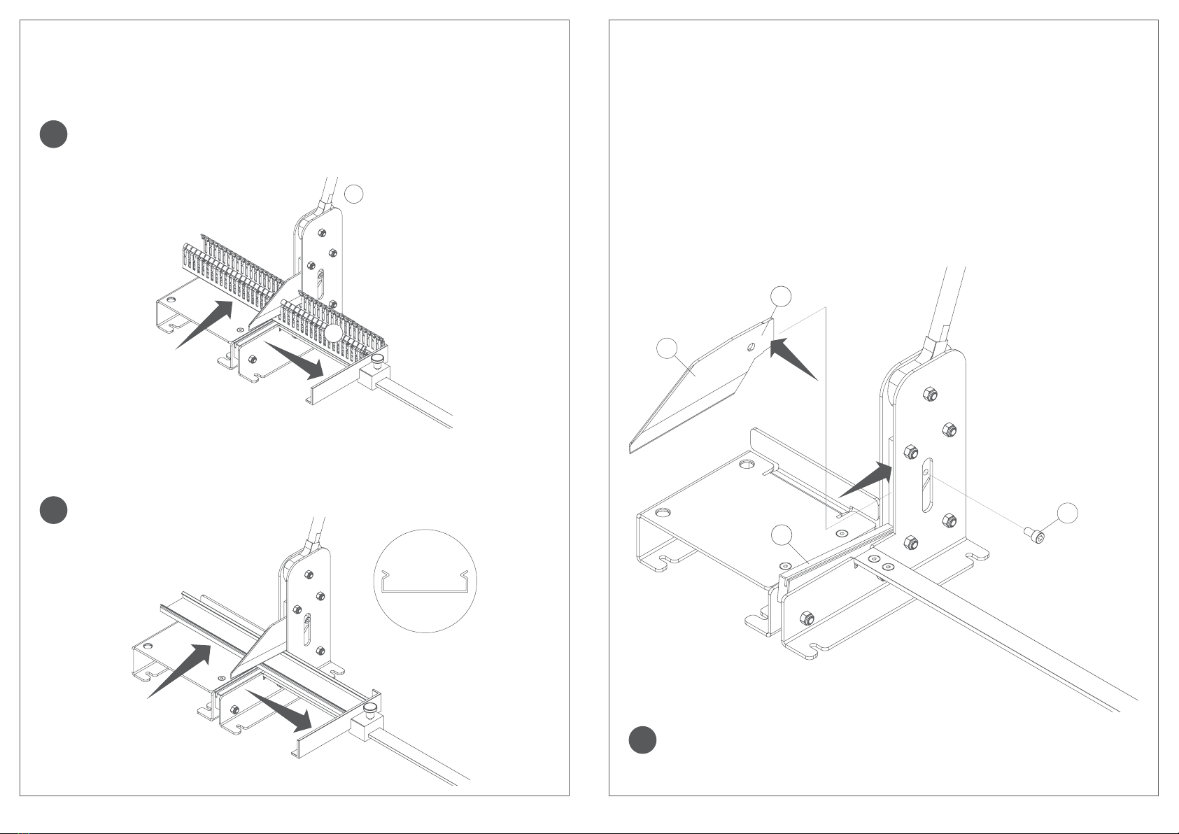
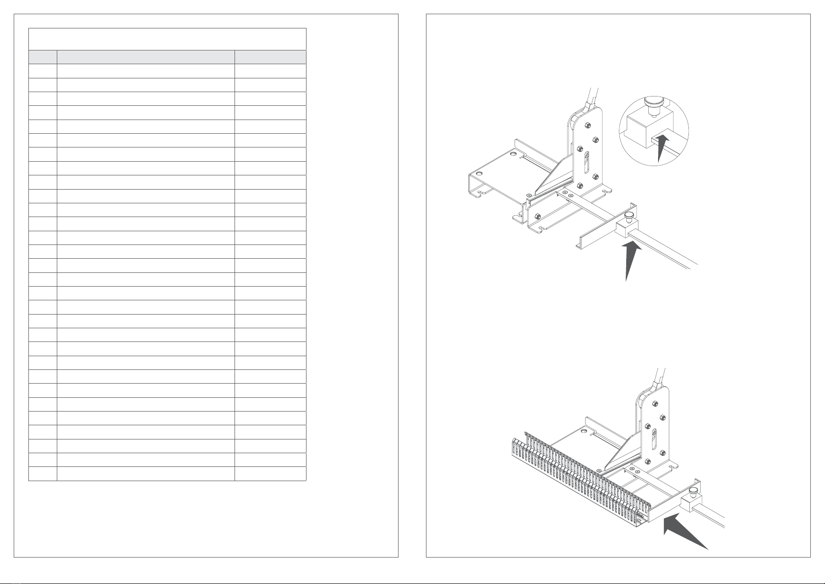
1. Die gewünschte Länge des Verdrahtungskanals am Längenanschlag einstellen und
mittels Flügelschraube die Position fixieren. Den Messerschutz mit dem Verdrahtungska-
nal nach unten drücken.
Maß hier ablesen
2. Den Verdrahtungskanal nur vorne außerhalb des Schneidbereichs und Messerlage
halten. Nicht hinter den Kanal fassen. Für das gewählte Schnittmaß den Verdrahtungska-
nal an Längenanschlag anlegen und dann komplett bis zum Gegenhalter in das Gerät ein-
schieben. Das Messer ist zwischen den Stegen einzufädeln, gegebenenfalls ist der Kanal
bis zum letzten Schlitz zurückzunehmen. Sollte das exakte Maß gewünscht werden, kann
der Steg ausgebrochen und an dessen Stelle geschnitten werden.
Distinta base pezzi di ricambio BA7CUTTER
Pos. Descrizione Paese di origine
01 Manopola ITALIA
02 Vite a testa cilindrica M6x12 mm ITALIA
03 Camma ITALIA
04 Boccola camma ITALIA
05 Spina camma ITALIA
06 Molla di compressione ITALIA
07 Fiancata destra ITALIA
08 Colonna di riferimento ITALIA
09 Colonna di riferimento protezione lama ITALIA
10 Portalama ITALIA
11 Vite testa cilindrica con esagono M8x35 ITALIA
12 Boccola di centraggio molla ITALIA
13 Lama ITALIA
14 Vite testa cilindrica con esagono M8x14 ITALIA
15 Protezione lama ITALIA
16 Boccola protezione lama ITALIA
17 Molla protezione lama ITALIA
18 Fiancata sinistra ITALIA
19 Boccola distanziale ITALIA
20 Vite testa svasata con esagono M6x14 ITALIA
21 Vassoio di appoggio ITALIA
22 Dado esagonale autobloccante M8 ITALIA
23 Piastrina di collegamento ITALIA
24 Dado esagonale autobloccante M6 ITALIA
25 Piedino asta millimetrata ITALIA
26 Asta millimetrata sinistra ITALIA
27 Asta millimetrata destra ITALIA
28 Base battuta ITALIA
29 Battuta canale ITALIA
30 Pomellino di serraggio ITALIA

05 22
!
!
5
6
!
4
1
3
2
3. Zum Schneiden den Handhebel nach unten ziehen und nach dem Schneidvorgang
wieder nach oben bringen. Die geschnittenen Kanalteile vorsichtig entnehmen. Eventuell
hierzu den Anschlag lösen um Teile freizulegen.
Der Messerschutz muß nach dem Schneidvorgang automatisch an das Messer
hochklappen. Ist der Schneidvorgang nur mit großem Kraftaufwand möglich,
ist das Messer stumpf oder defekt und muß ersetzt werden.
4. Zum Schneiden des Deckels die Schritte 1 - 3 wiederholen.
Die Abkantungen des Deckels müssen beim Schneiden nach oben zeigen.
JA
Manutenzione
1. Sostituzione lama
1.1. Per smontare la lama togliere la vite (2) ed estrarre la lama (1).
1.2. Lubrificare le superfici di appoggio della lama (3) indicate dalla freccia con l’olio multiu-
so fornito in dotazione.
1.3. Per montare la lama, spingere verso il basso la protezione lama (4) ed inserire la lama
(1) nell’alloggiamento fino all’arresto. Fissare con la vite (2).
Non immagazzinare la lama al di fuori dell’apparecchio nè trasportarla senza
una idonea protezione di sicurezza.

21 06
!
4
1
3
2
!
!
5
6
3. Per il taglio tirare la leva di comando verso il basso e riportarla in posizione alta dopo il
processo di taglio. Rimuovere con cautela i pezzi di canalina tagliati. Per sbloccare i pezzi,
allentare eventualmente l’arresto.
Dopo ogni processo di taglio la protezione deve essere in automatico
riposizionata sulla lama. Se il processo di taglio richiede troppo sforzo, la lama
non è affilata o è difettosa e deve essere sostituita.
4. Per tagliare il coperchio (ripetere i passi 1 e 3).
Durante il taglio i fianchi del coperchio devono essere rivolti verso l’alto.
SI
Wartung
1. Auswechseln des Messers.
1.1. Zum Ausbauen des Messers (2) die Schraube (1) entfernen und das Messer gerade
heraus ziehen.
1.2. Die Aufnahmeflächen (3) des Messers mit dem mitgelieferten Mehrzweckfett einfet-
ten.
1.3. Zum Einbauen des Messers (4) den Messerschutz nach unten drücken und das Mes-
ser bis zum Anschlag in die Aufnahme schieben. Mit Schraube befestigen.
Das Messer nicht ohne geeigneten Schneideschutz außerhalb des Gerätes
lagern oder transportieren.

07 20
Funzionamento
1. Impostare la lunghezza desiderata della canalina portacavi sull’arresto longitudinale e
fissarla mediante la vite ad alette. Spingere la protezione lama con la canalina portacavi
verso il basso.
Rilevare qui la misura
2. Tenere la canalina portacavi solo dal davanti, fuori dalla zona di taglio e dalla posizione
della lama. Non afferrare mai la canalina da dietro. Collocare la canalina portacavi sull’ar-
resto longitudinale per la quota di taglio desiderata ed inserirla del tutto nell’apparecchio
fino alla controtesta . La lama deve essere inserita tra i settori oppure la canalina deve
essere posizionata fino all’ultima fessura. Se si vuole ottenere una quota precisa, è possi-
bile rompere il settore e tagliare in corrispondenza di questo punto.
BA7CUTTER Ersatzteilliste
Pos. Beschreibung Ursprungsland
01 Griff ITALIEN
02 Zylinderschraube M6x12 mm ITALIEN
03 Exenter ITALIEN
04 Achse ITALIEN
05 Spannstift ITALIEN
06 Druckfeder ITALIEN
07 Seitenplatte rechts ITALIEN
08 Führung ITALIEN
09 Führung ITALIEN
10 Haltplatte für Messer ITALIEN
11 Zylinderschraube M6x35 mm ITALIEN
12 Druckstück ITALIEN
13 Messer ITALIEN
14 Zylinderschraube M6x14 mm ITALIEN
15 Messerschutz ITALIEN
16 Messerschutzbuchse ITALIEN
17 Messerschutzfeder ITALIEN
18 Seitenplatte links ITALIEN
19 Distanzbuchse ITALIEN
20 Spitzsenkschraube M6x14 mm ITALIEN
21 Gegenhalter mit Auflage ITALIEN
22 Sechskantmutter M6 ITALIEN
23 Verbindungsplatte ITALIEN
24 Sechskantmutter M8 ITALIEN
25 Winkel ITALIEN
26 Lineal links ITALIEN
27 Lineal rechts ITALIEN
28 Klotz für Anschlagwinkel ITALIEN
29 Anschlagwinkel ITALIEN
30 Befestigungsgriff ITALIEN

0819
21
11
19
02
30
01
15
20
13 07
03
04
05
19 28
29
23
10
11 12
06
14
08
16
09
25
24
26
27
19
19
18
11
24
22
22
17
1.2 Avvitare la leva di comando. Spostare l’arresto sulla guida. Utilizzando il materiale di
fissaggio in dotazione, montare la controtesta (appoggio laterale) e l’arresto longitudina-
le. Durante il montaggio, la guida dovrà essere settata con l’ausilio di un metro pieghevole
o un metro a nastro per la misura esatta (distanza tra lama e bordo esterno dell’arresto).
Detailliertes zeichnen

18
Attention
Security norms
The knife is very sharp. Do not reach into the cutting area and do not touch the edge
of the knife.
The cutting area is to be kept clean. It’s absolutely necessary that the scrap is removed
from the cutting area. Remove parts, e.g. chips, rejects with suitable and safe tools.
Risk of injury.
The device must be completely mounted on a firm and tilt-proof basis before operating.
The mounting parts are not included. Please use suitable and rugged mounting parts
according to the basis.
For ideal cutting results and operation of the device the knife has always to be sharp. If
dull it has to be exchanged.
The spring-loaded blade guard has to fold up promptly after the cutting procedure. If this
feature does not work the knife has to be secured or removed immediately to avoid inju-
ries. Before operating the device again the blade guard has to be repaired or exchanged.
Specified condition use
The bench mount wiring duct cutting tool VTC125 is only to be used to cut plastic wiring
ducts and covers up to a width of 125 mm and a wall thickness up to 2,5 mm.
It’s only suitable for PVC.
09
!
Messa in servizio
1. Montaggio
1.1 Fissaggio su un supporto stabile, protetto contro eventuali ribaltamenti (ad es. banco
da lavoro).
Stabilire la posizione e fissare l’apparecchio. Usare il materiale di fissaggio
idoneo. (non in dotazione)

1017
Commissioning
1. Assembly
2. Attachment on a firm and tilt-proof basis e.g. workbench.
Set position and location of the device and transfer attachment points to
basis suitable mounting parts (not included).
!
Attenzione
Norme di sicurezza
Lama di taglio molto affilata. Non afferrare mai la lama dalla zona di taglio.
Tenere sempre la zona di taglio pulita. Rimuovere con strumenti sicuri ed idonei
(pericolo di lesioni) eventuali elementi estranei, ad es. scaglie o ritagli.
L’apparecchio può essere messo in funzione solo una volta garantito il suo corretto
montaggio su un supporto stabile dove non possa essere ribaltato.
Il materiale di fissaggio dell’apparecchio non è in dotazione.
Usare materiale di fissaggio stabile ed idoneo al relativo supposto.
Al fine di ottenere prestazioni e risultati di taglio ottimali, la lama deve essere sempre
affilata. Sostituire la lama priva di affilatura.
Dopo ogni processo di taglio è necessario riposizionare la protezione flessibile sulla lama.
Uso previsto
Con la cesoia da banco VTC125 possono essere tagliate le canaline da cablaggio e
rispettivi coperchi in fino alla larghezza massima di 125 mm e spessore di 2,5 mm.
Adatto per canaline in PVC.

1611
1.2 Screw the lever. Attach the length stopper to the ruler. Mount the counter support
and the ruler by using the included mounting parts. The ruler has to be adjusted to the
exact gauge (distance between knife and the outer edge of the length stopper) by using a
tape-measure or a folding ruler.
Detailed drawing
21
11
19
02
30
01
15
20
13 07
03
04
05
19 28
29
23
10
11 12
06
14
08
16
09
25
24
26
27
19
19
18
11
24
22
22
17

1215
Operation
1. Adjust the desired length of the wiring duct by using the length stopper and lock posi-
tion by screwing down the thumbscrew. Push down the blade guard with the wiring duct.
Measurement indicator
2. Hold the wiring duct only at the front and outside of the cutting area and the blade
position. Do not reach behind the wiring duct. For the desired cutting dimension connect
the wiring duct to the length stopper then slide it completely back against the counter
support . The blade has to be placed between the bars. Possibly the duct has to be moved
back to the previous slot. If the exact dimension is desired the according bar can be bro-
ken out and it can be cut on its place.
BA7CUTTER spare part list
Pos. Description Country of origin
01 Handle ITALY
02 Cylindric screw M6X12 mm ITALY
03 Cam ITALY
04 Cam bush ITALY
05 Cam tap ITALY
06 Compression spring ITALY
07 Right side ITALY
08 Reference post ITALY
09 Blade protection reference post ITALY
10 Blade holder ITALY
11 Cylindric screw M8X35 mm ITALY
12 Spring bush ITALY
13 Blade ITALY
14 Cylindric screw M8X14 mm ITALY
15 Blade protection ITALY
16 Blade protection bush ITALY
17 Blade protection spring ITALY
18 Left side ITALY
19 Spacer bush ITALY
20 Flared screw M6X14 ITALY
21 Bearing tray ITALY
22 Hexagonal nut M8 ITALY
23 Connection plate ITALY
24 Hexagonal nut M6 ITALY
25 Support for millimetric pole ITALY
26 Left millimetric pole ITALY
27 Right millimetric pole ITALY
28 Abutting end base ITALY
29 Trunking abutting end ITALY
30 Tightening handle ITALY

1413
3. To cut, pull the lever down. After the cutting, press the lever back up and carefully re-
move the cut duct parts. For this perhaps the length stopper has to be loosened.
The blade guard has to fold up against the blade automatically after every
cutting procedure. If the cutting can be done only with great effort the blade
is dull or damaged. It has to be exchanged.
4. To cut covers please (repeat steps 1 and 3).
The rims of the cover must be on top when cutting.
!
!
YES
5
6
Maintenance
1. Replacement of the blade.
1.1. To remove the blade, remove the screw (2) and pull the blade straight out (1).
1.2. Grease the slide faces of the blade (3) with the included multi-purpose grease.
1.3. To install the knife depress the blade guard (4) and slide the blade (1) back on to the
holding fixture. Then tighten the screw (2).
Do not transport or store the blade without suitable cut protection.
!
4
1
3
2
Table of contents
Popular Cutter manuals by other brands

IronCraft
IronCraft 2512 Series Operation and parts manual

Hypertherm
Hypertherm HyPerformance Plasma HPR260 instruction manual

Hypertherm
Hypertherm PMX1000 Field Service Bulletin

EBA
EBA 551-06 operating instructions

Makita
Makita 4100NH instruction manual

Mafell
Mafell KSS40 18 M bl Translation of the original operating instructions