manuals.online logo
Brands
  1. Home
  2. •
  3. Brands
  4. •
  5. Haier
  6. •
  7. Air Conditioner
  8. •
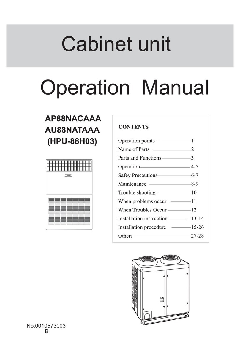
  9. Haier HDU-42CH03 User manual

Haier HDU-42CH03 User manual

This manual suits for next models

13

Other Haier Air Conditioner manuals

Haier AS35TADHRA-CL User manual

Haier

Haier AS35TADHRA-CL User manual

Haier HWE18VCN User manual

Haier

Haier HWE18VCN User manual

Haier HWF05XC7 User manual

Haier

Haier HWF05XC7 User manual

Haier H2SM- User manual

Haier

Haier H2SM- User manual

Haier Smart Power Series User manual

Haier

Haier Smart Power Series User manual

Haier HSU-22H03/R2 User manual

Haier

Haier HSU-22H03/R2 User manual

Haier HSU-12HM03-R2 User manual

Haier

Haier HSU-12HM03-R2 User manual

Haier QHC08 User manual

Haier

Haier QHC08 User manual

Haier AU082AJNAA User manual

Haier

Haier AU082AJNAA User manual

Haier AS09FBBHRA User manual

Haier

Haier AS09FBBHRA User manual

Haier 1U09JE7ERA User manual

Haier

Haier 1U09JE7ERA User manual

Haier 1U25MECFRA-3 User manual

Haier

Haier 1U25MECFRA-3 User manual

Haier HSU22VCA User manual

Haier

Haier HSU22VCA User manual

Haier HSU12XCK User manual

Haier

Haier HSU12XCK User manual

Haier HWR05XCR User manual

Haier

Haier HWR05XCR User manual

Haier AU482FIBHA User manual

Haier

Haier AU482FIBHA User manual

Haier HSU-18CI03 User manual

Haier

Haier HSU-18CI03 User manual

Haier HWR18VC3 User manual

Haier

Haier HWR18VC3 User manual

Haier HWR08XC5-T User manual

Haier

Haier HWR08XC5-T User manual
Haier HM-09C12 User manual

Haier

Haier HM-09C12 User manual

Haier AB122XCBAA Instruction Manual

Haier

Haier AB122XCBAA Instruction Manual

Haier 10530627 User manual

Haier

Haier 10530627 User manual

Haier AU282FHERA(H) User manual

Haier

Haier AU282FHERA(H) User manual

Haier AD25S2PS1FA User manual

Haier

Haier AD25S2PS1FA User manual

Popular Air Conditioner manuals by other brands

Fujitsu ASYG 09 LLCA installation manual

Fujitsu

Fujitsu ASYG 09 LLCA installation manual

York HVHC 07-12DS Installation & owner's manual

York

York HVHC 07-12DS Installation & owner's manual

Carrier Fan Coil 42B Installation, operation and maintenance manual

Carrier

Carrier Fan Coil 42B Installation, operation and maintenance manual

intensity IDUFCI60KC-3 installation manual

intensity

intensity IDUFCI60KC-3 installation manual

Frigidaire FAC064K7A2 Factory parts catalog

Frigidaire

Frigidaire FAC064K7A2 Factory parts catalog

Sanyo KS2432 instruction manual

Sanyo

Sanyo KS2432 instruction manual

LG MultiV Series installation manual

LG

LG MultiV Series installation manual

CLIMAVENETA a-CHD U-2T 606+2209 OPERATING AND INSTALLATION Manual

CLIMAVENETA

CLIMAVENETA a-CHD U-2T 606+2209 OPERATING AND INSTALLATION Manual

Midea EWK06CW5 user manual

Midea

Midea EWK06CW5 user manual

Pioneer FAB Series installation manual

Pioneer

Pioneer FAB Series installation manual

SPT WA-1511S user manual

SPT

SPT WA-1511S user manual

Mitsubishi Electric Mr.Slim MSZ-A24NA operating instructions

Mitsubishi Electric

Mitsubishi Electric Mr.Slim MSZ-A24NA operating instructions

Mitsubishi Electric PUHZ-RP50VHA4 Service manual

Mitsubishi Electric

Mitsubishi Electric PUHZ-RP50VHA4 Service manual

Panasonic CS-S18HKQ Service manual

Panasonic

Panasonic CS-S18HKQ Service manual

Panasonic CS-E15NKE3 operating instructions

Panasonic

Panasonic CS-E15NKE3 operating instructions

Gree GWH18TC-K3DNA1B/I Service manual

Gree

Gree GWH18TC-K3DNA1B/I Service manual

Friedrich ZoneAire Compact P08SA owner's manual

Friedrich

Friedrich ZoneAire Compact P08SA owner's manual

Daikin R32 Split Series installation manual

Daikin

Daikin R32 Split Series installation manual

manuals.online logo
manuals.online logoBrands
  • About & Mission
  • Contact us
  • Privacy Policy
  • Terms and Conditions

Copyright 2025 Manuals.Online. All Rights Reserved.

ROOM AIR CONDITIONER
OUTDOOR UNIT
No.0010576723
H
Before using he air condi ioner,please read his manual carefully.
Please keep his manual properly for fu ure use.
CONTENTS
Name of Parts----------------------1
Safety Cautions------------------2-3
Installation Procedure---------4-13
INSTALLATION INSTRUCTIONS
HB -42CF03 HD -42CF03/H
HB -42HF03 HD -42CH03/H
HB -28CF03
HB -28HF03
HD -42HF03/H
HD -42CI03/H
HD -42HK03/H
HD -50HT03/H
Name of Par s
1
HB -42CF03
HB -42HF03
HD -42CF03/H
HD -42CH03/H
HB -28CF03
Air inle
Air ou le
(Inside of unit)
Compressor
Air inle
Air ou le
(Inside of unit)
Compressor
HB -28HF03
Air inle
Air ou le
(Inside of unit)
Compressor
Air inle
Air ou le
(Inside of uni )
Compressor
HD -42HF03/H
HD -42CI03/H
HD -42HK03/H
HD -50HT03/H
Below are listed three kinds of Safety Cautions and Suggestions.
WARNING!
CAUTION! Incorrect operations may result in injuries or machine damages; in some cases may
cause serious consequences.
Incorrect operations may result in severe consequences of death or serious injuries.
INSTRUCTIONS: These information can ensure the correct operation of the machine.
Be sure to conform with the following important Safety Cautions.
The Safe y Cau ions should be a hand so ha hey can be checked a any ime when needed.
If the conditioner is transferred to the new user, this manual should be as well transferred to the
new user.
Safe y Cau ions
Carefully read he following informa ion in order o opera e he aircondi ioner
correc ly.
WARNING!
If any abnormal phenomena is found
(e. g.smell of firing), please cu off he
power supply immedia ely, and con ac
he dealer o find ou he handling
me hod.
Don' disman le he ou le of he
ou door uni .
The exposure of fan is very dangerous
whichmay harm human beings.
switch
off
In such case, to continue using the
conditioner will damage the conditioner,
and may cause electrical shock or fire
hazard.
Incorrect maintenance and repairment
may cause water leak, electrical shock
and fire hazard.
When need main enance and repairmen ,
call dealer o handle i .
Af er a long ime use of air-condi ioner
he base should be checked for any
damages.
If the damaged base is not repaired, the
unit may fall down and cause accidents.
2
Air-condi ioner can' be ins alled in
he environmen wi h inflammable
gases because he inflammable gases
near o air-condi ioner may cause fire
hazard.
Connec ear hing wire.
Use discharge pipe correc ly o ensure
efficien discharge.
Earthing wire should not be con-
nected to the gas pipe, water pipe,
lightning rod or phone line, in-
correct earthing may cause shock.
Incorrect pipe use may cause water
leaking.
Earthing
Safe y Cau ions
WARNING!
Ins alled elec rical-leaking circui
breaker.
It easily cause electrical shock without
circuit breaker.
Please le he dealer be responsible for
ins alling he condi ioner.
Incorrect installation may cause water
leak, electrical shock and fire hazard.
Call he dealer o ake measures o
preven he refrigeran from leaking.
If conditioner is installed in a small
room be sure to take every measure in
order to prevent suffocation accident
even in case of refrigerant leakage.
When condi ioner is deins alled or
reins alleddealer should be respon-
sible for hem.
Incorrect installation may cause water
leaking, electrical shock and fire hazard.
No goods or nobody is permi ed o
placed on or s and on ou door uni .
The falling of goods and people may
cause accidents.
Don' opera e he air-condi ioner wi h
damp hands.
Otherwise will be shocked.
Only use correc ly- yped fuse.
May not use wire or any other materials
replacing fuse, other-wise may cause
faults or fire accidents.
3
Note :
(1). Fix the parts with screws
(2).Don't intake the strong wind directly to the
outlet air-flow hole.
(3).A one meter distance should be kept from the
unit top
(4).Don't block the surroundings of the unit with
sundries
Ins alla ion Procedure
2. Selec ion of he place of ins alla ion
1. Accessories
"Edging" for protection of electric wires from an
opening edge.
Select the place of installation satisfying the following conditions and, at the
same time, obtain a consent from the client or user.
Edging
Place where air circulates.
Place free from heat radiation from other heat sources.
Place where drain water may be discharged.
Place where noise and hot air may not disturb the neighborhood.
Place where there is not heavy snowfall in the winter time.
Place where obstacles do not exist near the air inlet and air outlet .
Place where the air outlet may not be exposed to a strong wind.
Place surrounded at four sides are not suitable for installation. A 1m or more
of overhead space is needed for the unit.
Mount guide-louvers to place where short-circuit is a possibility.
When installing several units, secure sufficient suction space to avoid short
circuiting.
Wind direction
NO
(2) Ins alla ion where he area wi h s rong winds.
Install the unit so that the air outlet section of the unit must NOT be faced
toward wind direction.
(1) Open space requiremen around he uni
L
2
L
3
L
1
500
(Servicing
space)
Air outlet
Air inlet
Air
inlet
Case
Distance
nit: mm
open open
open
500
150
150 300
300 0
L1
L2
L3
III III
Ins alla ion of ou door uni
4
(2) Ins alla ion ske ch of ou door uni
310
3. Ins alla ion of ou door uni
Fix the unit in a proper way according to the condition of a place where it is
installed by referring to the following .
(1) Ins alla ion
Ins alla ion of ou door uni
5
Ins alla ion Procedure
635
340
Power Wiring Terminal
Power Wiring
Distribution Hole
25
862
730
HB -28CF03
(b) Foundation anchor
(a) Concrete foundation
Install the unit so that the angle of inclination must be less than 3 degrees.
Note: (1) Give enough room for the concrete
foundation to fix by anchor bolts. Note: (1) Place the concrete foundation deep enough.
nit
To fix by bolts
Anchor bolt Concrete foundation
nit
Concrete foundation
Anchor bolt
(a) Concrete foundation (b) Foundation anchor
Concrete foundation
nit
Anchor bolt
Anchor bolt
Concrete foundation
nit
To fix by bolts
340
410
Ins alla ion of ou door uni
6
Ins alla ion Procedure
580
380
Power Wiring Terminal
Power Wiring
Distribution Hole
25
948
840
HB -28HF03
Power Wiring Terminal
Power Wiring
Distribution Hole
646
447
25
1008
830
HB -42CF03 HD -42CF03/H
HB -42HF03 HD -42CH03/H
340
Outdoor
unit
Gas pipe
Liquid
pipe
Flare connection
Indoor
unit
3-way stop valve
3-way stop valve
Ins alla ion of ou door uni
7
Ins alla ion Procedure
Outdoor
unit
Gas pipe
Liquid
pipe
Flare connection
Indoor
unit
3-way stop valve
2-way stop valve
4. Refrigeran piping
580
380
948 Power wiring Terminal
25
1250
HD -42CI03/H HD -42HK03/H
HD -42HF03/H
HB -28HF03
HB -28CF03 HB -42CF03 HB -42HF03 HD -42CI03/H HD -42CH03/H
HD -42CF03/H HD -42HF03/H¡¡ HD -50HT03/H HD -42HK03/H¡¡¡¡
HD -50HT03/H
(2) Piping size
Install the removed flare nuts to
the pipes to be connected, then
flare the pipes.
(3) Limi a ions for one way piping leng h and ver ical heigh difference.
Precautions for refrigerant piping
Do not twist or crush piping.
Be sure that no dust is mixed in piping.
Bend piping with as wide angle as possible.
Keep insulating both gas and liquid piping.
Check flare-connected area for gas leakage.
Connecting method (indoor unit)
Apply refrigerant oil at half union as large and flare nut.
To bend a pipe, give the roundness as possible not to crush
the pipe.
When connecting pipe, hold the pipe centre to centre then
screw nut on by hand, refer to Fig.
Be careful not to let foreign matters, such as sands enter
the pipe.
(4) Piping connec ion
Forced fastening without centering
may damage the threads and cause a
gas leakage.
Pipe dia Fastening torque
Liquid pipe 6.35mm
Gas pipe 15.88mm
Liquid pipe 9.52mm
Gas pipe 19.05mm
14.2-17.2N.m
61.8-75.4N.m
32.7-39.9N.m
97.2-118.6N.m
Gas pipe 12.7mm 49.5-60.3N.m
HD -42CH03/H HD -42CI03/H
HD -42HK03/H HD -50HT03/H
Gas pipe
Liquid pipe
Gas pipe
9.52x0.8mm
15.88x1.0mm
9.52x0.8mm
19.05x1.0mm
Liquid pipe
Refrigeran piping
8
90+0.5
Ins alla ion Procedure
Model
One way piping length Vertical height difference
(between indoor and outdoor)
less than 40 m
HB -42CF03 HB -42HF03
HD -42CF03/H HD -42HF03/H
HB -28CF03 HB -28HF03
less than 50 m
less than 15 m
less than 30 m
HBU-42CF03
HBU-42HF03
HDU-42CF03/H
HBU-28CF03
HBU-28HF03
HDU-42HF03/H
HDU-50HT03/H
HDU-42CH03/H
HDU-42CI03/H
HDU-42HK03/H
In the first to third test steps, if the pressure drops, check the leakage in each joint
use sense of hearing, feeling and soap water, etc. methods to find the leaking point.
After confirming the leaking point, welding it again or tighten the nut tightly again.
Checking the leaking point
First step: 0.3MPa (3.
0kg/cm
2
g) pressurize
over 3 minutes.
Second step: 1.5Mpa
(15kg/cm
2
g) pressurize
over 3 minutes. Large
leakage will be found.
Third step: 3.0 MPa
(30kg/cm
2
g) pressurize
about 24 hours. Little
leakage will be found.
After finishing connection of refrigerant pipe, it shall perform air tightness test.
The air tightness test adopts nitrogen tank to give pressure according to the pipe connection
mode as the following figure shown.
The gas and liquid valve are all in close state. In order to prevent the nitrogen entering the
circulation system of outdoor unit, tighten the valve rod before giving pressure (both gas
and liquid valve rods).
Outdoor
Completely tightened
Flare part
Outdoor units
Manhole
Discharging valve
3-way valve totally closed
(Gas side)
Low pressure peizometer
High pressure peizometer
Meter separator
Dropping valve
2-way or 3-way valve totally closed
(Liquid side)
Nitrogen tank
VL VH
Indoor units
Indoor
Flare part
9
From pressurizing to 24 hours later, each 1¡ difference of ambient temperature
will make 0.01MPa(0.1kg/cm2g) pressure change. It shall be corrected during test.
Check if the pressure drops
The pressure does not drop-passed
The pressure drops-check the leaking point.
5. Air discharging me hod
CYLINDER
OF
NITROGEN
SERVICE
HO SE
LARGE
SLIP-ON
CONNECTOR
SWEAT
JOINT
T BING
BRING
BRAZED
LINE
PRESS RE
GA GE
CYLINDER
PRESS RE
GA GE
Ins alla ion Procedure
Refrigeran piping